2020 VOLKSWAGEN TRANSPORTER remove seats
[x] Cancel search: remove seatsPage 134 of 486
t"""""fl1 First read and observe the introductory l..--bll information and safety warnings & on page 133.
Removing plastic covers
The plastic covers=:. Fig. 107 must be removed from the seat rails, if seats or the central table are to be installed or removed.
• Take the screwdriver from the vehicle tootkit.
• Insert the flat blade of the screwdriver into the seat rail at an angle in front of the plastic cover you wish to remove G).
• Press the cover lug approx. 3 mm to the front and, at the same time, lever it out.
Removing split cover rail
• Grasp with both hands into the rubber lip of the shorter part (approx. 30 cm) of the aluminium cov-er rail ®. and push it towards the front until both clips are released.
• Remove cover rail@ upwards in a straight line.
• Now, also move the opposite part of the alumi-nium cover rail towards the front, and remove it up-wards in a straight line.
• Repeat this procedure for all seat rails.
Installing split cover rail
• Fit the aluminium cover rail so that it is flush with the longer part of the cover rail.
• Push the aluminium cover rail from above into the clips of the seat rail until it engages.
• Repeat this procedure for all seat rails.
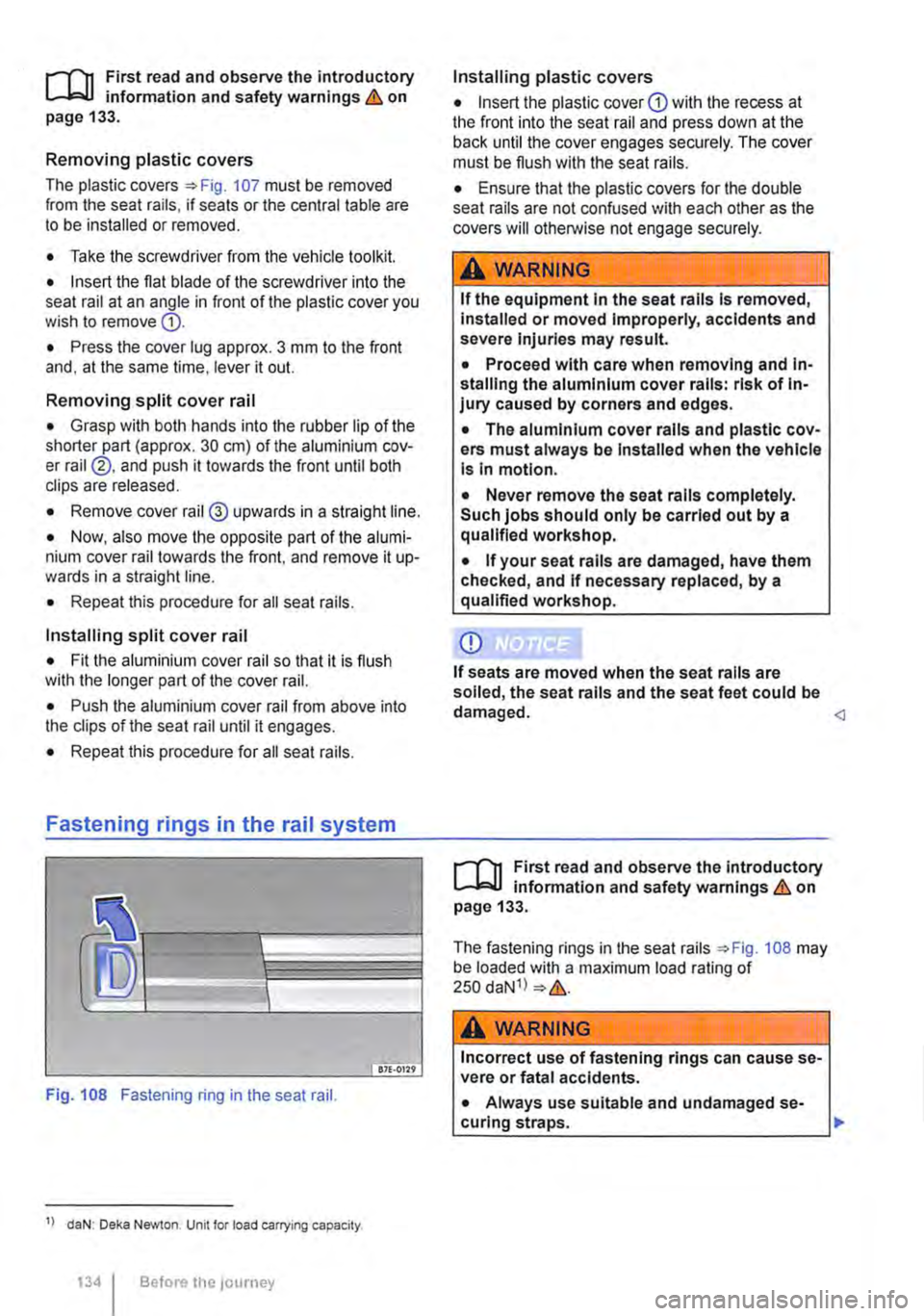
Fastening rings in the rail system
Fig. 108 Fastening ring in the seat rail.
1> daN: Deka Newton. Unit for load carrying capacity.
134 Before the JOUrney
Installing plastic covers
• Insert the plastic cover CD with the recess at the front into the seat rail and press down at the back until the cover engages securely. The cover must be flush with the seat rails.
• Ensure that the plastic covers for the double seat rails are not confused with each other as the covers will otherwise not engage securely.
A WARNING
If the equipment In the seat rails Is removed, Installed or moved Improperly, accidents and severe Injuries may result.
• Proceed with care when removing and In-stalling the aluminium cover rails: risk of In-jury caused by corners and edges.
• The aluminium cover rails and plastic cov-ers must always be Installed when the vehicle Is In motion.
• Never remove the seat rails completely. Such jobs should only be carried out by a qualified workshop.
• If your seat rails are damaged, have them checked, and If necessary replaced, by a qualified workshop.
CD
If seats are moved when the seat rails are soiled, the seat rails and the seat feet could be damaged.
The fastening rings in the seat rails ::.Fig. 108 may be loaded with a maximum load rating of 250 daN1l ::.&.
A wARNING
Incorrect use of fastening rings can cause se-vere or fatal accidents.
• Always use suitable and undamaged se-curing straps. ..,.
Page 137 of 486
n11 First read and observe the introductory l-J=,IJ information and safety warnings & on page 133.
The net partition can prevent objects in the lug-gage compartment entering the passenger com-partment.
The net partition can be fitted behind the front seats or behind the 3-seat bench.
Key to Fig. 111:
® Cross pieces with joints which lock into place
Preparing the net partition for fitting
• Take the net partition out of its plastic bag and unroll it fully.
• Fold out all the side rods fully, until you hear a "clicking• noise.
Fitting the net partition
• Make sure that the sewn-in instructions label is pointing to the rear.
• Hook the net partition up onto the left-hand side
• Push the rod together to hook the net partition onto the right-hand side.
• Pull the net partition to check that it has engag-ed securely in the retainers in the headliner.
• On the left and right sides. pull the strap down on the loop G) until you can insert the T-shaped holder into the outer seat rails.
• Turn each of the T-shaped holders through 90° so that they are positioned across the seat rails @.
• Make sure that the net partition is vertical and securely fitted in the seat rails.
Roof carrier
COl Introduction
This chapter contains information on the following subjects:
Attaching the mounts and roof carrier . . . . . . . 138 Loading the roof carrier . . . . . . . . . . . . . . . . . . . 139
Removing the net partition
• Slacken off the straps by pulling loop
• Push the net partition on one side slightly to the inside of the vehicle and lift it out of the upper re-tainer.
• Press the release button 111 ® in the joint of each cross piece and fold the cross pieces together.
• Roll up the net partition and stow it in its plastic bag.
• Stow the plastic bag securely in the vehicle.
A WARNING
Always use the net partition carefully, observ-Ing the Instructions. Risk of injury.
• The net partition is secured properly in the roof only if the T-shaped holders are securely fitted Into the retainers.
• The net partition is fitted correctly in the seat rails only if the T-shaped retainers are at right-angles to the seat rails and correctly en-gaged.
• The T-shaped holders must never be fitted close to the removable covers on the seat rails.
• Heavy, pointed or sharp items which are not stowed securely can cause Injury in the event of sudden braking manoeuvres or acci-dents. This may also happen when the net partition is fitted correctly.
• Vehicle occupants must not travel behind a fitted safety net.
• When it is no longer being used.
• When the vehicle is driving through a car wash.
• When the vehicle height exceeds the required clearance height, e.g. in a garage. .,.
Transporting items 1137
Page 157 of 486
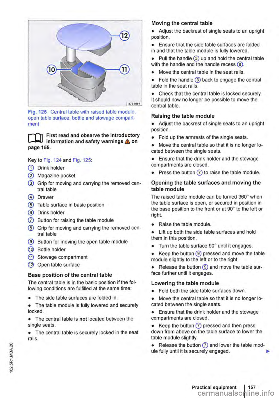
Fig. 125 Central table with raised table module, open table surface. bottle and stowage compart-ment
r-1'11 First read and observe the Introductory l.-Jr:-lJ Information and safety warnings & on page 155.
Key to Fig. 124 and Fig. 125:
G) Drink holder
0 Magazine pocket
® Grip for moving and carrying the removed cen-tral table
@ Drawer
® Table surface in basic position
® Drink holder
0 Button for raising the table module
® Grip for moving and carrying the removed cen-tral table
® Button for moving the open table module
® Bottle holder
® Stowage compartment
@ Open table surface
Base position of the central table
The central table is in the basic position if the fol-lowing conditions are fulfilled at the same time:
• The side table surfaces are folded in.
• The table module is fully lowered and securely locked.
• The central table is not located between the single seats.
• The central table is securely locked in the seat rails.
Moving the central table
• Adjust the backrest of single seats to an upright position.
• Ensure that the side table surfaces are folded in and that the table module is fully lowered.
• Pull the handle® up and hold the central table wilh the handle and the handle recess @.
• Move the central table in the seat rails.
• Fold the handle® back to engage the central table in the seat rails.
• Check that the central table is locked securely. lt should now no longer be possible to move the central table.
Raising the table module
• Adjust the backrest of single seats to an upright position.
• Fold up the armrests of the single seats.
• Move the central table so that it is no longer lo-cated between the single seats.
• Ensure that the drink holder and the stowage compartments are closed.
• Press the button 0 to raise the table module.
Opening the table surfaces and moving the
table module
The raised table module can be turned 36o• when the table surface is open, or secured in position in the base position to the front or at go• to the left or rig hi.
• Raise lhe table module.
• Lift up both the side table surfaces and hold them in this position.
• Turn the table surface go• until it engages.
• Keep the button ® pressed and move the table module slightly to the left or to the right.
• Release the button ® and move the table sur-face further until it engages.
Lowering the table module
• Fold both the side table surfaces down.
• Move the central table so that it is no longer lo-cated between the single seats.
• Ensure that the drink holder and the stowage compartments are closed.
• Keep the button 0 pressed and then press down from above on the table surface to lower the table module slightly.
• Release the button 0 and lower lhe table mod-ule fully until it is securely engaged. .,.
Practical equipment 1157
Page 158 of 486
Removing the central table
The central table can be removed more easily by two people than by one person.
• Remove front protective covers from the central seat rails.
• Turn the single seats so that they face the di-rection of travel.
• Adjust the back rest of single seats to an upright position.
• Fold up the armrests of the single seats.
• Pull the handle @ up and hold the central table with the handle and the handle recess@.
• Push the central table forwards to the point where it can be lifted out of the slots in the seat rails.
• Lift the central table out.
• Put down the central table carefully so that the rollers and feet are not soiled or damaged.
• Place the removed covers on the open slots in the seat rails.
Fitting the central table
The central table can be installed more easily by two people than by one person.
• Remove front protective covers from the central seat rails.
• Turn the single seats so that they face the di-rection of travel.
Cool box
c:cn Introduction
This chapter contains information on the following subjects:
Fitting and removing the cool box
Switching the cool box on and off 159 161
The cool box may be used while the vehicle is in motion only if it is fitted to the adapter plate.
Power for the cool box can be supplied by any of the 12-volt sockets in the vehicle. The power con-sumption is approx. 33 watts. The cool box has a capacity of 32 litres.
Follow instructions provided for the installation and use of the cool box and keep it in the vehicle wal-let.
As far as possible, keep food and drinks in the cool box in leak-proof containers. Do not overfill the cool box such that air circulation is impaired.
158 Before the journey
• Adjust the backrest of single seats to an upright position.
• Fold up the armrests of the single seats.
• Pull the handle @ up and hold the central table with the handle and the handle recess®.
• Insert the central table guides into the recesses in the seat rails.
• Insert the central table into the seat rails and push them back, so that the removed covers can be placed on the open slots in the seat rails.
• Fold the handle@ back to engage the central table in the seat rails.
• Check that the central table is locked securely. it should now no longer be possible to move the central table.
• Do not raise the table module when the cen-tral table Is located between the single seats. This could cause damage to the table.
The vehicle battery will be drained if the cool box is used when the engine is switched off. For this rea-son, the cool box is fitted with a battery monitor. The battery monitor will switch the cool box off if the vehicle battery has a low charge level. The bat-tery monitor will switch the cool box on again as soon as the battery has reached a suitable charge level, for example, after a long journey.
Additional information and warnings:
• Seat functions, front =>page 69
• Seat functions, rear =>page 72
• Seat functions, rear, Business =>page 182
• Seat functions, rear, California =>page 193
• Electrical sockets =>page 163
• Battery =>page 350
Page 196 of 486
• Make sure that the backrest of the bench seaU bed is in the upright position and securely engag-ed.
Bed (bench seat/bed)
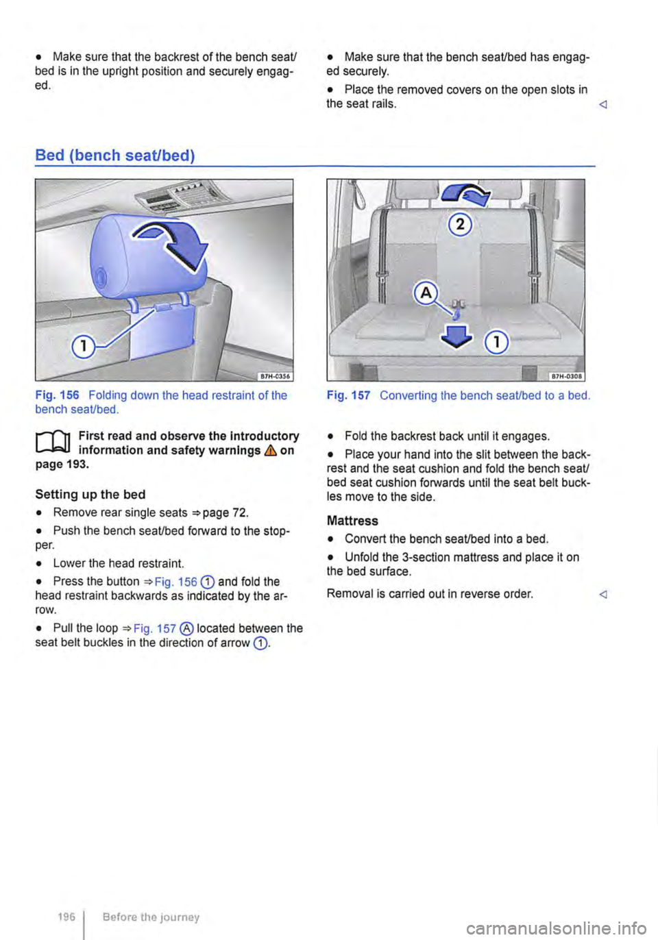
Fig. 156 Folding down the head restraint of the bench seaUbed.
r-111 First read and observe the Introductory 1-J,::JJ information and safety warnings & on page 193.
Setting up the bed
• Remove rear single seats =>page 72.
• Push the bench seaUbed forward to the stop-per.
• Lower the head restraint.
• Press the button =>Fig. 156 G) and fold the head restraint backwards as indicated by the ar-row.
• Pull the loop =>Fig. 157 ® located between the seat belt buckles in the direction of arrow G).
1961 Before the journey
• Make sure that the bench seaUbed has engag-ed securely.
• Place the removed covers on the open slots in the seat rails.
• Fold the backrest back until it engages.
• Place your hand into the slit between the back-rest and the seat cushion and fold the bench seaU bed seat cushion forwards until the seat belt buck-les move to the side.
Mattress
• Convert the bench seaUbed into a bed.
• Unfold the 3-section mattress and place it on the bed surface.
Removal is carried out in reverse order.
Page 198 of 486
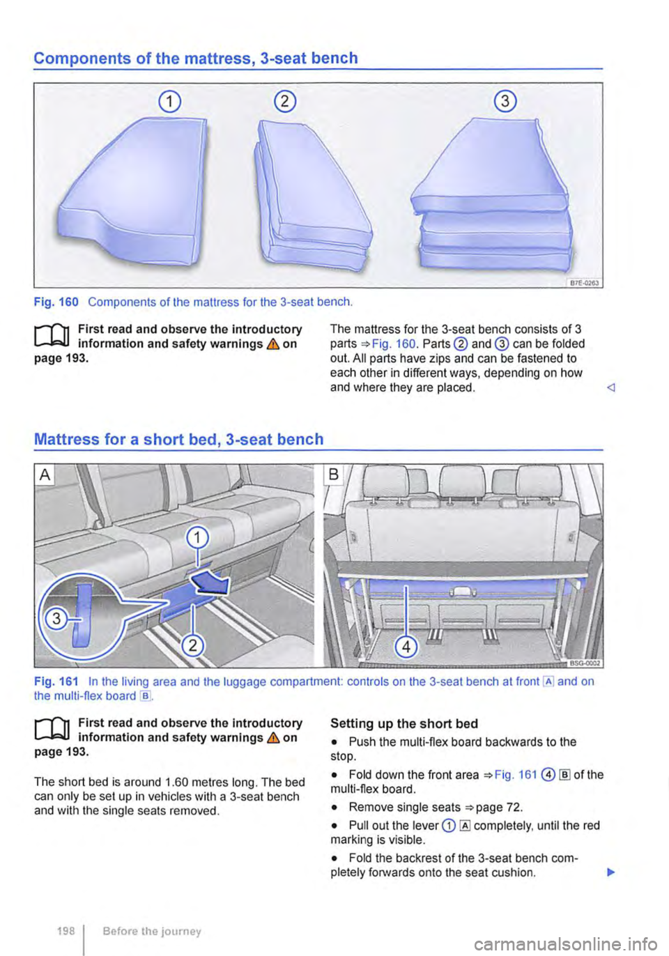
Components of the mattress, 3-seat bench
87E-0263
Fig. 160 Components of the mattress for the 3-seat bench .
.--m First read and observe the introductory l.-l=.U information and safety warnings & on page 193.
Mattress for a short bed, 3-seat bench
The mattress for the 3-seat bench consists of 3 parts 160. Parts@ and@ can be folded out. All parts have zips and can be fastened to each other in different ways, depending on how and where they are placed.
.--m First read and observe the Introductory l.-l=.U information and safety warnings & on page 193.
The short bed is around 1.60 metres long. The bed can only be set up in vehicles with a 3-seat bench and with the single seats removed.
198 I Before the journey
Setting up the short bed
• Push the multi-flex board backwards to the stop.
• Fold down the front area 161 @[ID of the multi-flex board.
• Remove single seats 72.
• Pull out the lever CD completely, until the red marking is visible.
• Fold the backrest of the 3-seat bench com-pletely forwards onto the seat cushion. 11>
Page 199 of 486
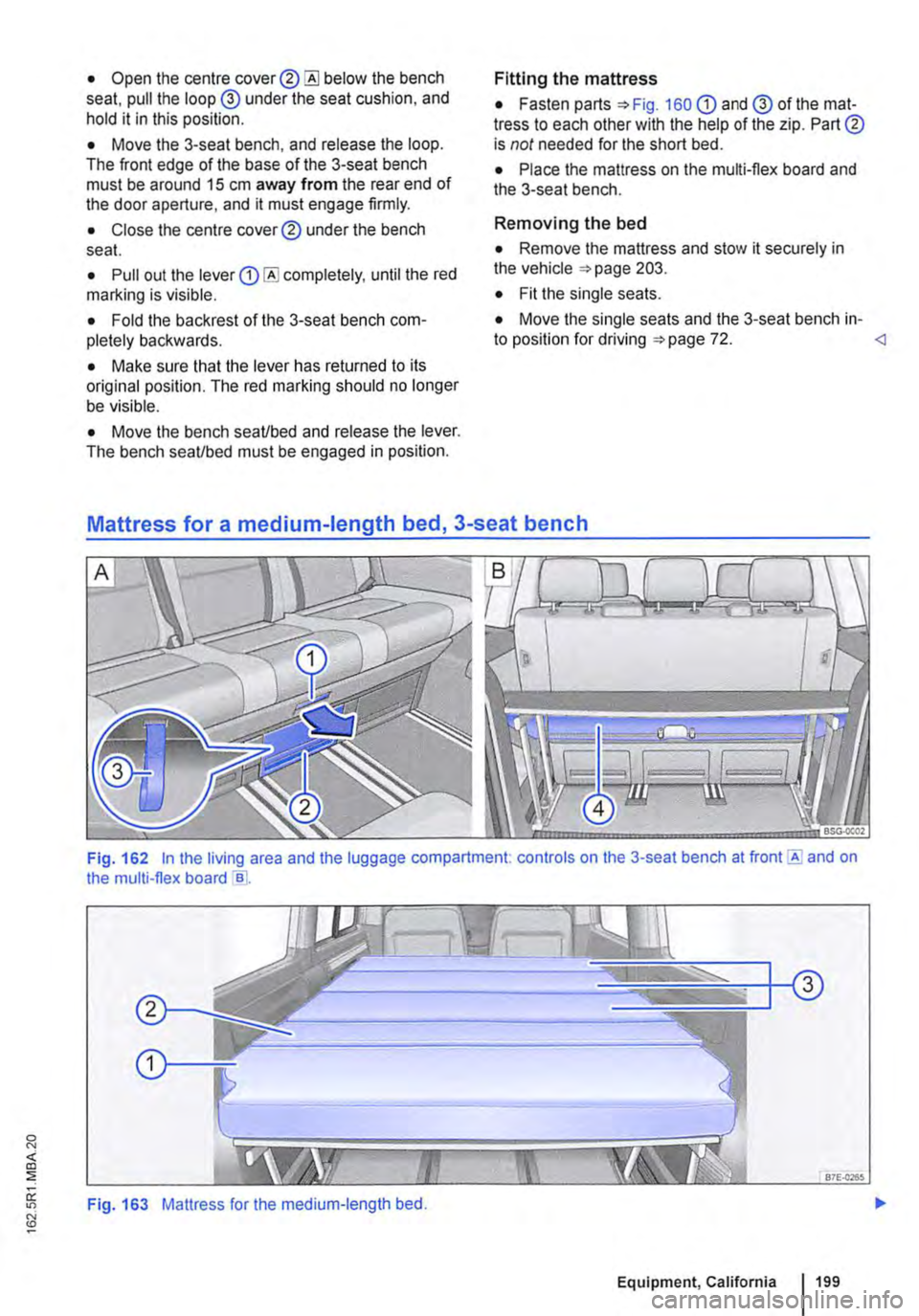
• Open the centre cover® below the bench seat, pull the loop @ under the seat cushion, and hold it in this position.
• Move the 3-seat bench, and release the loop. The front edge of the base of the 3-seat bench must be around 15 cm away from the rear end of the door aperture, and it must engage firmly.
• Close the centre cover® under the bench seat.
• Pull out the lever completely, until the red marlling is visible.
• Fold the backrest of the 3-seat bench com-pletely backwards.
• Make sure that the lever has returned to its original position. The red marking should no longer be visible.
• Move the bench seaVbed and release the lever. The bench seaVbed must be engaged in position.
Fitting the mattress
• Fasten parts =>Fig. 160 G) and @ of the mat-tress to each other with the help of the zip. Part® is not needed for the short bed.
• Place the mattress on the multi-flex board and the 3-seat bench.
Removing the bed
• Remove the mattress and stow it securely in the vehicle =>page 203.
• Fit the single seats.
• Move the single seats and the 3-seat bench in-to position for driving =>page 72.
Fig. 162 In the living area and the luggage compartment. controls on the 3-seat bench at front E and on the multi-flex board e .
Fig. 163 Mattress for the medium-length bed.
Equipment, California 199
Page 200 of 486
,...-m First read and observe the Introductory L--W.I Information and safety warnings & on page 193.
The medium-length bed is around 1.80 metres long. The bed can only be set up In vehicles with a 3-seat bench and with the single seats removed.
Setting up the medium-length bed
• Push the multi-flex board backwards to the stop.
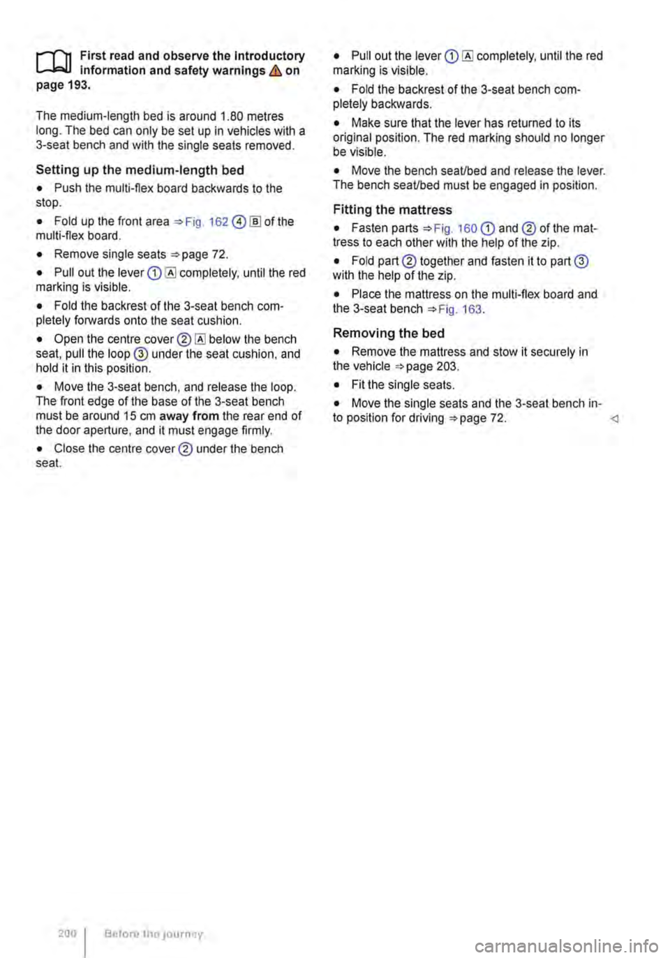
• Fold up the front area 162 @!ID of the multi-flex board.
• Remove single seats 72.
• Pull out the lever completely, until the red marking is visible.
• Fold the backrest of the 3-seat bench com-pletely forwards onto the seat cushion.
• Open the centre below the bench seat, pull the loop @ under the seat cushion, and hold it in this position.
• Move the 3-seat bench, and release the loop. The front edge of the base of the 3-seat bench must be around 15 cm away from the rear end of the door aperture, and it must engage firmly.
• Close the centre cover® under the bench seat.
200 Before tho JOurney
• Pull out the lever completely, until the red marking is visible.
• Fold the backrest of the 3-seat bench com-pletely backwards.
• Make sure that the lever has returned to its original position. The red marking should no longer be visible.
• Move the bench seaUbed and release the lever. The bench seaUbed must be engaged in position.
Fitting the mattress
• Fasten parts 160 CD and® of the mat-tress to each other with the help of the zip.
• Fold part® together and fasten it to part@ with the help of the zip.
• Place the mattress on the multi-flex board and the 3-seat bench 163.
Removing the bed
• Remove the mattress and stow it securely in the vehicle 203.
• Fit the single seats.
• Move the single seats and the 3-seat bench in-to position for driving 72.