2020 Ram ProMaster City ignition
[x] Cancel search: ignitionPage 63 of 350

60 GETTING TO KNOW YOUR VEHICLE
(Continued)
WINDOWS
Power Windows — If Equipped
Power Window Switch Panel
The control on the left front door panel has up-down
switches that give you fingertip control of all power
windows. There is a single opening and closing switch on the
front passenger door for passenger window control. If the vehicle is equipped with rear power windows, a single
opening and closing switch on the rear passenger doors for
passenger window control is provided.
NOTE:
The key off power delay feature will allow the power
windows to operate for up to three minutes after the ignition
is turned off. This feature is canceled when either front door
is opened.
The window opening mechanism is fitted with sensors that
can detect the presence of an obstacle while the window is
closing. When this happens, the system activates and the
movement of the glass is immediately reversed.
If the presence of an object is detected and the system is acti
-
vated, it may be necessary to perform the reset procedure by
fully opening the windows.
1 — Rear Window Control Buttons (If Equipped)
2 — Driver Passenger Window Control Buttons
3 — Rear Window Lock ButtonWARNING!
• Never leave children alone in a vehicle, or with access to an unlocked vehicle. Allowing children to be in a
vehicle unattended is dangerous for a number of
reasons. A child or others could be seriously or fatally
injured. Children should be warned not to touch the
parking brake, brake pedal or the gear selector.
2020_RAM_PROMASTER_CITY_OM_USA=GUID-7B6A7FCA-79B0-423F-95C5-ED2A949C3D13=1=en=.book Page 60
Page 64 of 350

GETTING TO KNOW YOUR VEHICLE 61
Auto-Down Feature
The window switches are equipped with an Auto-Down
feature. Push the window switch for half a second, release,
and the window will go down automatically.
To stop the window from going all the way down during the
auto-down operation, pull up or push down on the switch
briefly.
To open the window part way, lift the window switch to the
detent for less than half a second and release it to stop the
window.
NOTE:
The power window switches remain active for up to three
minutes after the ignition switch has been turned off.
Opening either of the vehicle’s front doors will cancel this
feature.Auto-Up Feature
The window switches are equipped with an Auto-Up
feature. Lift the window switch to the detent for half a
second, release, and the window will go up automatically.
To stop the window from going all the way up during the
auto-up operation, pull up/push down on the switch briefly.
To close the window part way, lift the window switch to the
detent for less than half a second and release it when you
want the window to stop.
• Do not leave the key fob in or near the vehicle or in a
location accessible to children. A child could operate
power windows, other controls, or move the vehicle.
WARNING! (Continued)
WARNING!
There is no auto-reverse protection when the window is
almost closed. Be sure to clear all objects from the
window before closing.
2
2020_RAM_PROMASTER_CITY_OM_USA=GUID-7B6A7FCA-79B0-423F-95C5-ED2A949C3D13=1=en=.book Page 61
Page 71 of 350

68 GETTING TO KNOW YOUR VEHICLE
INTERNAL EQUIPMENT
Storage
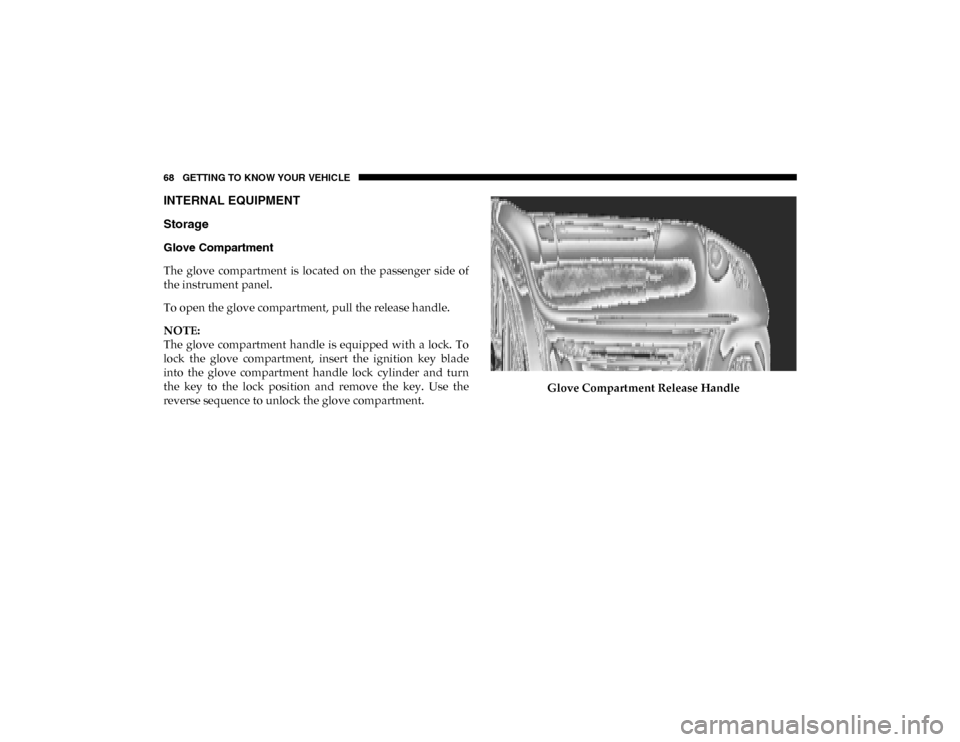
Glove Compartment
The glove compartment is located on the passenger side of
the instrument panel.
To open the glove compartment, pull the release handle.
NOTE:
The glove compartment handle is equipped with a lock. To
lock the glove compartment, insert the ignition key blade
into the glove compartment handle lock cylinder and turn
the key to the lock position and remove the key. Use the
reverse sequence to unlock the glove compartment.Glove Compartment Release Handle
2020_RAM_PROMASTER_CITY_OM_USA=GUID-7B6A7FCA-79B0-423F-95C5-ED2A949C3D13=1=en=.book Page 68
Page 73 of 350

70 GETTING TO KNOW YOUR VEHICLE
Power Outlets
Your vehicle is equipped with 12 Volt (15 Amp) power
outlets that can be used to power cellular phones, small elec-
tronics and other low powered electrical accessories. The
power outlets are labeled with either a “key” or a “battery”
symbol to indicate how the outlet is powered. Power outlets
labeled with a “key” are powered when the ignition is in the
MAR (ACC/ON/RUN) position, while the outlets labeled
with a “battery” are connected directly to the battery and
powered at all times.
NOTE:
• All accessories connected to the “battery” powered outlets should be removed or turned off when the vehicle is not in
use to protect the battery against discharge. Driver And Front Passenger Power Outlets
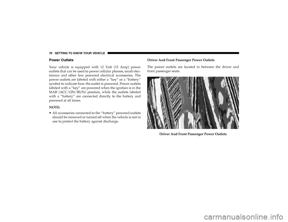
The power outlets are located in between the driver and
front passenger seats.
Driver And Front Passenger Power Outlets
2020_RAM_PROMASTER_CITY_OM_USA=GUID-7B6A7FCA-79B0-423F-95C5-ED2A949C3D13=1=en=.book Page 70
Page 79 of 350

76 GETTING TO KNOW YOUR INSTRUMENT PANEL
Instrument Cluster Descriptions
1. Speedometer• Indicates vehicle speed.
2. Fuel Gauge
• The pointer shows the level of fuel in the fuel tankwhen the ignition switch is in the ON/RUN position.
• The fuel pump arrow symbol points to the side of the vehicle where the fuel door is located.
3. Temperature Gauge
• The temperature gauge shows engine coolant tempera-ture. Any reading within the normal range indicates that
the engine cooling system is operating satisfactorily.
• The pointer will likely indicate a higher temperature when driving in hot weather or up mountain grades. It
should not be allowed to exceed the upper limits of the
normal operating range.
WARNING!
A hot engine cooling system is dangerous. You or others
could be badly burned by steam or boiling coolant. You
may want to call an authorized dealer for service if your
vehicle overheats. If you decide to look under the hood
yourself, refer to “Cooling System Pressure Cap” in
“Servicing And Maintenance” and follow the warnings
under the Cooling System Pressure Cap paragraph.
CAUTION!
Driving with a hot engine cooling system could damage
your vehicle. If the temperature gauge reads “H,” pull
over and stop the vehicle. Idle the vehicle with the air
conditioner turned off until the pointer drops back into
the normal range. If the pointer remains on the “H,” turn
the engine off immediately and call an authorized dealer
for service.
2020_RAM_PROMASTER_CITY_OM_USA=GUID-7B6A7FCA-79B0-423F-95C5-ED2A949C3D13=1=en=.book Page 76
Page 80 of 350

GETTING TO KNOW YOUR INSTRUMENT PANEL 77
4. Tachometer• Indicates the engine speed in revolutions per minute(RPM x 1000).
5. Instrument Cluster Display
• When the appropriate conditions exist, this displayshows the instrument cluster display messages. Refer
to “Instrument Cluster Display” in this chapter for
further information.
INSTRUMENT CLUSTER DISPLAY
Your vehicle will be equipped with an instrument cluster
display, which offers useful information to the driver. With
the ignition in the OFF mode, opening/closing of a door will
activate the display for viewing, and display the total miles,
or kilometers, in the odometer. Your instrument cluster
display is designed to display important information about
your vehicle’s systems and features. Using a driver interac -
tive display located on the instrument panel, your instru-
ment cluster display can show you how systems are working and give you warnings when they are not. The instrument
cluster display controls allow you to scroll through the main
menus and submenus. You can access the specific informa
-
tion you want and make selections and adjustments.
Location And Controls
The instrument cluster display features a driver interactive
display that is located in the instrument cluster.
Instrument Cluster Display Location3
2020_RAM_PROMASTER_CITY_OM_USA=GUID-7B6A7FCA-79B0-423F-95C5-ED2A949C3D13=1=en=.book Page 77
Page 83 of 350

80 GETTING TO KNOW YOUR INSTRUMENT PANEL
Change Engine Oil — If Equipped
Your vehicle may be equipped with an engine oil change
indicator system. The “Change Engine Oil” message will
display in the instrument cluster display. The engine oil
change indicator system is duty cycle based, which means
the engine oil change interval may fluctuate, dependent
upon your personal driving style.
Unless reset, this message will continue to display each time
you turn the ignition switch to the ON/RUN position. To
turn off the message temporarily, push and release the
MENU button. To reset the oil change indicator system (after
performing the scheduled maintenance), refer to the
following procedure.
1. Turn the ignition switch to the ON position (do not start the engine).
2. Fully push the accelerator pedal slowly, three times, within 10 seconds.
3. Turn the ignition switch to the OFF/LOCK position.
NOTE:
If the indicator message illuminates when you start the
vehicle, the oil change indicator system did not reset. If
necessary, repeat this procedure.
Instrument Cluster Display Menu Items
Speed Beep
This function is used to set a speed limit (MPH or km/h); the
driver is alerted when this limit is exceeded.
To set the desired speed limit:
1. Push the MENU button briefly. The display will show the
wording (SPEED BEEP) and the unit (MPH) or (km/h)
previously set.
2. If the function is on, push and release the up or down
arrow button to select the required speed limit and then
push MENU to confirm.
NOTE:
The speed may be set in the range from 20 to 125 MPH (30 to
200 km/h) according to the previously chosen unit.
The setting will increase/decrease by five units each time the
up or down arrow button is pushed. Hold down the up or
down arrow button to automatically increase/decrease the
setting rapidly. Complete the adjustment when you
approach the desired value.
2020_RAM_PROMASTER_CITY_OM_USA=GUID-7B6A7FCA-79B0-423F-95C5-ED2A949C3D13=1=en=.book Page 80
Page 86 of 350

GETTING TO KNOW YOUR INSTRUMENT PANEL 83
Start Of Trip Procedure
With the ignition on, push and hold the TRIP button for over
two seconds to reset trip information.
Exit Trip
1. To exit the Trip function, wait until all the values havebeen displayed or hold the MENU button for longer than
one second.
2. Briefly push and release the MENU button to go back to the menu screen or push and hold the MENU button
(approximately one second) to go back to the main screen
without storing settings.
Trip Functions
Both trip functions are resettable (reset — start of new trip).
“Trip A” can be used to display the figures relating to:
• Range
• Trip distance A
• Average Economy A
• Instantaneous Economy • Average speed A
• Travel time A (driving time)
“Trip B” can be used to display the figures relating to:
• Trip distance B
• Average Economy B
• Average speed B
• Travel time B (driving time)
NOTE:
“Trip B” functions may be excluded (see “Trip B Data”).
“Range” and “Instantaneous Economy” cannot be reset.
Values Displayed
Range
This indicates the distance which may be traveled with the
fuel remaining in the tank, assuming that driving conditions
will not change. The message “----” will appear on the
display in the following cases:
• Distance less than 30 miles (or 50 km).
• The vehicle is parked for a long time with the engine
running.
3
2020_RAM_PROMASTER_CITY_OM_USA=GUID-7B6A7FCA-79B0-423F-95C5-ED2A949C3D13=1=en=.book Page 83