2020 Peugeot Partner tailgate
[x] Cancel search: tailgatePage 91 of 260

89
Safety
5Manual child lock
Mechanical system to prevent opening of the
sliding side door using its interior lever.
Locking/Unlocking
► Rotate the control located on the edge of the
side door up
to lock it, or down to unlock it.
Electric child lock
Remote control system to prevent opening of the
rear doors (sliding side door(s), side-hinged rear
doors or tailgate) using their interior controls.
Activation/Deactivation
► With the ignition on, press this button to
activate/deactivate the child lock.
When the indicator lamp is on, the child lock is
activated.
With the child lock activated, it is still
possible to open the doors from outside.
In the event of a serious impact, the
electric child lock is deactivated (child
lock off) automatically.
Any other state of the indicator lamp indicates a fault with the electric child
lock.
Have it checked by a PEUGEOT dealer or a
qualified workshop.
This system is independent and in no circumstances does it take the place of
the central locking control.
Do not drive with the sliding side door open.
Check the status of the child lock each time
you switch on the ignition.
Always remove the key from the ignition when
leaving the vehicle, even for a short time.
Page 131 of 260

129
Driving
6installed in accordance with the
manufacturer's recommendations.
In this case, the outline of a trailer is displayed
at the rear of the image of the vehicle.
Operating limits
If the boot is heavily loaded, the vehicle may tilt,
affecting distance measurements.
Malfunction
In the event of a malfunction when
changing into reverse, this warning lamp
comes on on the instrument panel, accompanied
by an onscreen message and an audible signal
(short beep).
Contact a PEUGEOT dealer or a qualified
workshop to have the system checked.
Reversing camera
Refer to the General recommendations on the
use of driving and manoeuvring aids .
With the ignition on, this system uses a camera
located near the third brake lamp to display
a view of the rear of your vehicle on the
reproduction screen (if it is a panel van or has a
solid partition).
The reversing camera is activated automatically
when reverse gear is engaged. The image
is displayed on the reproduction screen. The
reproduction screen switches off when the
gearbox is in neutral or in a forward gear.
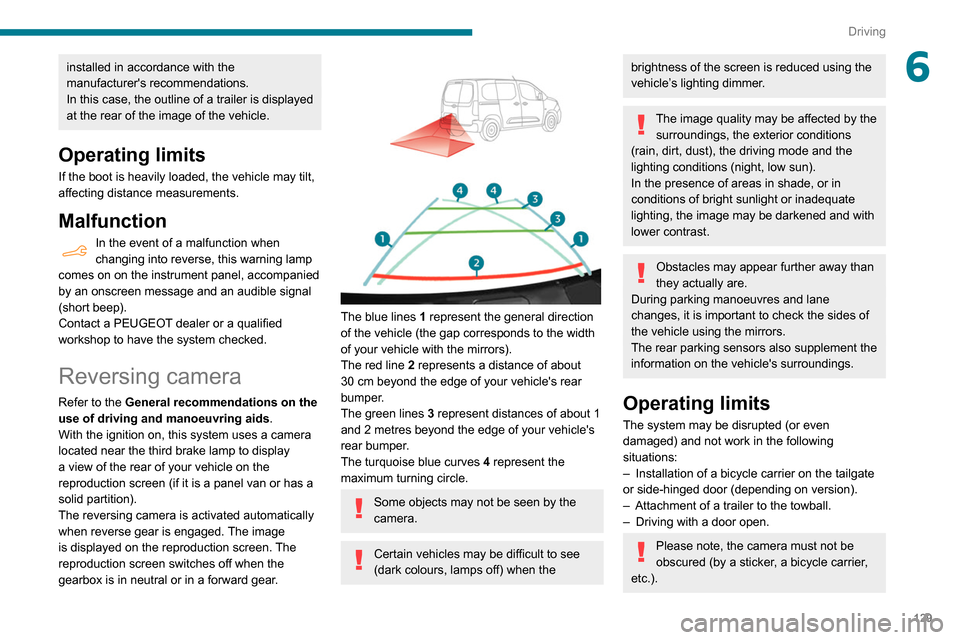
The blue lines 1 represent the general direction
of the vehicle (the gap corresponds to the width
of your vehicle with the mirrors).
The red line 2 represents a distance of about
30
cm beyond the edge of your vehicle's rear
bumper.
The green lines 3 represent distances of about 1
and 2 metres beyond the edge of your vehicle's
rear bumper.
The turquoise blue curves 4 represent the
maximum turning circle.
Some objects may not be seen by the
camera.
Certain vehicles may be difficult to see
(dark colours, lamps off) when the
brightness of the screen is reduced using the
vehicle’s lighting dimmer.
The image quality may be affected by the surroundings, the exterior conditions
(rain, dirt, dust), the driving mode and the
lighting conditions (night, low sun).
In the presence of areas in shade, or in
conditions of bright sunlight or inadequate
lighting, the image may be darkened and with
lower contrast.
Obstacles may appear further away than
they actually are.
During parking manoeuvres and lane
changes, it is important to check the sides of
the vehicle using the mirrors.
The rear parking sensors also supplement the
information on the vehicle's surroundings.
Operating limits
The system may be disrupted (or even
damaged) and not work in the following
situations:
–
Installation of a bicycle carrier on the tailgate
or side-hinged door (depending on version).
–
Attachment of a trailer to the towball.
–
Driving with a door open.
Please note, the camera must not be
obscured (by a sticker, a bicycle carrier,
etc.).
Page 134 of 260

132
Driving
The area around the vehicle is shown by the monitoring rear view and the
passenger side view only.
Operating limits
The system may be disrupted (or even
damaged) and not work in the following
situations:
–
Installation of a bicycle carrier on the tailgate
or side-hinged door (depending on version).
–
Attachment of a trailer to the towball.
–
Driving with a door open.
Please note, the cameras must not be
obscured (by a sticker, a bicycle carrier,
etc.).
The field of vision of the rear camera (surveillance rear view and visual
reversing aid) may vary depending on the
load in the vehicle.
If the side-hinged door is opened during
use of the surveillance rear view or the
visual aid for reversing, in forward gear or
reverse gear, the output screen becomes
grey.
If the front passenger door is opened during
use of the passenger side view, in forward
gear or reverse gear, the output screen
becomes grey.
If a trailer is attached to the towball,
when reverse gear is engaged the visual
reversing aid will no longer work until the
trailer is disconnected. The surveillance rear
view becomes the default view.
If the system develops a malfunction, go
to a PEUGEOT dealer to avoid any
safety problems.
Maintenance
recommendations
In bad or wintry weather, ensure that the sensors
and cameras are not covered with mud, ice or
snow.
Regularly inspect the camera lenses to check
that they are clean. If necessary, clean the cameras with a soft, dry
cloth.
Page 155 of 260

153
In the event of a breakdown
8With a tyre repaired using this type of kit,
do not exceed a speed of 50 mph
(80
km/h) and do not drive more than
125
miles (200 km).
Contact a PEUGEOT dealer or a qualified
workshop to have the tyre changed.
Checking / adjusting tyre
pressures
The compressor can be used, without injecting
sealant, to check and, if necessary, adjust the
tyre pressures.
►
Remove the valve cap from the tyre and keep
it in a clean place.
►
Uncoil
the pipe stowed under the compressor.
►
Screw the pipe onto the valve and tighten
firmly
.
►
Check that the compressor switch is in
position " O
".
►
Fully uncoil the electric cable stowed under
the compressor
.
►
Connect the compressor's electric plug to the
vehicle's 12
V socket.
►
Switch on the ignition.
Only the 12 V socket located at the front
of the vehicle can be used to power the
compressor .
The tyre inflation pressures are given on
this label.
► Start the compressor by placing the switch at
position " I
" and adjust the pressure to the value
shown on the vehicle's tyre pressure label. To
deflate: press the black button located on the
compressor pipe, near the valve connection.
If after 7 minutes the pressure of 2 bars
is not reached, this indicates that the tyre
is damaged; contact a PEUGEOT
dealer or a
qualified workshop for assistance.
►
Once the correct pressure is reached, put the
switch in position " O
".
►
Remove the kit and stow it.
Should the pressure of one or more tyres
be adjusted, it is necessary to reinitialise
the under-inflation detection system.
For more information on Tyre under-inflation
detection, refer to the corresponding section.
Spare wheel
Scan the QR code on page 3 to view
explanatory videos.
Procedure for changing a damaged wheel with
the spare wheel using the tools provided with the
vehicle.
For more information on the Tool kit,
refer to the corresponding section.
►
Park the vehicle, taking care to avoid
obstructing traffic, and apply the parking brake.
►
Follow the safety instructions (hazard
warning lamps, warning triangle, wearing high
visibility vest, etc.) according to the legislation in
force in the country where you are driving.
►
Switch off the ignition.
Access to the spare wheel
► Access to the spare wheel is from the rear .
► If your vehicle is fitted with a towbar, raise
the rear of the vehicle using the jack (must be
at jacking point B) to allow sufficient space to
remove the spare wheel.
Removing the spare wheel from the
carrier
► Depending on version, open the tailgate or
side-hinged doors.
Page 162 of 260

160
In the event of a breakdown
Rear lamps
For more information on Changing a bulb
and, in particular, the types of bulb, refer to the
corresponding section.
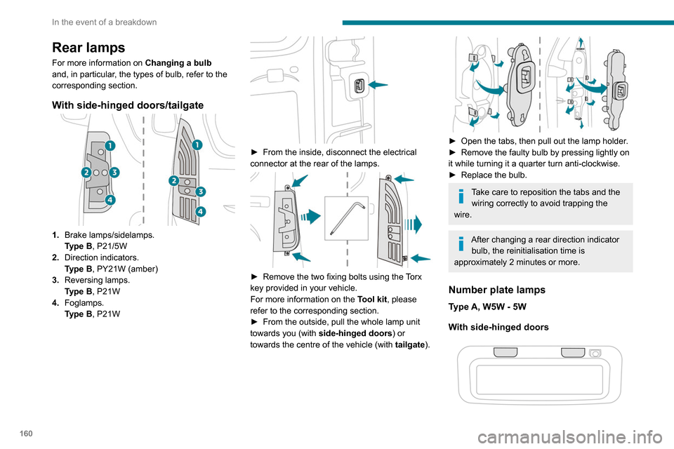
With side-hinged doors/tailgate
1. Brake lamps/sidelamps.
Type
B, P21/5W
2. Direction indicators.
Type
B, PY21W (amber)
3. Reversing lamps.
Type
B, P21W
4. Foglamps.
Type
B, P21W
► From the inside, disconnect the electrical
connector at the rear of the lamps.
► Remove the two fixing bolts using the Torx
key provided in your vehicle.
For more information on the Tool kit, please
refer to the corresponding section.
►
From the outside, pull the whole lamp unit
towards you (with side-hinged doors ) or
towards the centre of the vehicle (with tailgate
).
► Open the tabs, then pull out the lamp holder .
► Remove the faulty bulb by pressing lightly on
it while turning it a quarter turn anti-clockwise.
►
Replace the bulb.
Take care to reposition the tabs and the wiring correctly to avoid trapping the
wire.
After changing a rear direction indicator bulb, the reinitialisation time is
approximately 2 minutes or more.
Number plate lamps
Type A, W5W - 5W
With side-hinged doors
► Unclip the interior trim.
► Disconnect the connector by moving aside
its tab.
► Turn the bulb holder a quarter turn
anti-clockwise.
► Change the bulb.
► Put the bulb holder back in place and
reconnect the connector.
► Put the trim back in place.
With tailgate
► Remove the plastic lens using a screwdriver.
► Change the bulb.
► Refit the plastic lens and press on it.
Third brake lamp
Type A, W16W - 16W
– Unscrew the two nuts.
Page 163 of 260

161
In the event of a breakdown
8► Unclip the interior trim.
► Disconnect the connector by moving aside
its tab.
►
T
urn the bulb holder a quarter turn
anti-clockwise.
►
Change the bulb.
►
Put the bulb holder back in place and
reconnect the connector
.
►
Put the trim back in place.
With tailgate
► Remove the plastic lens using a screwdriver .
► Change the bulb.
►
Refit the plastic lens and press on it.
Third brake lamp
Type A, W16W - 16W
– Unscrew the two nuts. –
Push the rods.
–
If necessary
, disconnect the connector to
remove the lamp.
–
Replace the bulb.
Changing a fuse
Accessing the tools
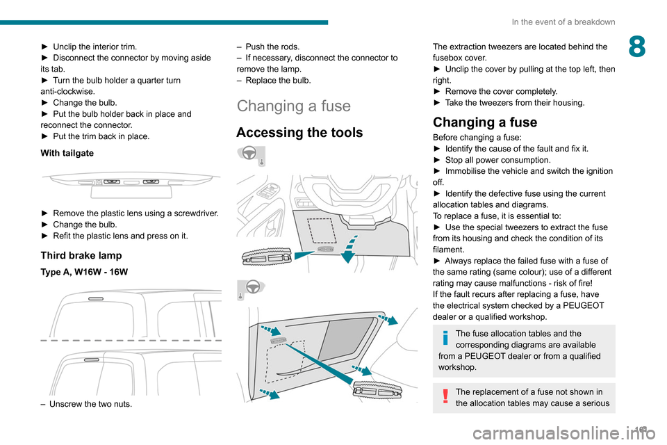
The extraction tweezers are located behind the
fusebox cover.
►
Unclip the cover by pulling at the top left, then
right.
►
Remove the cover completely
.
►
T
ake the tweezers from their housing.
Changing a fuse
Before changing a fuse:
► Identify the cause of the fault and fix it.
►
Stop all power consumption.
►
Immobilise the vehicle and switch the ignition
off.
►
Identify the defective fuse using the current
allocation tables and diagrams.
T
o replace a fuse, it is essential to:
►
Use the special tweezers to extract the fuse
from its housing and check the condition of its
filament.
►
Always replace the failed fuse with a fuse of
the same rating (same colour); use of a different
rating may cause malfunctions - risk of fire!
If the fault recurs after replacing a fuse, have
the electrical system checked by a PEUGEOT
dealer or a qualified workshop.
The fuse allocation tables and the corresponding diagrams are available
from a PEUGEOT dealer or from a qualified
workshop.
The replacement of a fuse not shown in the allocation tables may cause a serious
Page 167 of 260

165
In the event of a breakdown
8To charge the vehicle's battery yourself, use only a charger compatible with
lead-acid batteries with a nominal voltage of
12
V.
Follow the instructions provided by the
manufacturer of the charger.
Never reverse polarities.
It is not necessary to disconnect the
battery.
►
Switch off the ignition.
►
Switch off all electrical consumers (audio
system, lighting, wipers, etc.).
► Switch off charger B before connecting
the cables to the battery, so as to avoid any
dangerous sparks.
►
Ensure that the charger cables are in good
condition.
► Lift the plastic cover on the (+) terminal, if the
vehicle has one.
►
Connect the cables of charger B
as follows:
•
the positive (+) red cable to the (+) terminal
of battery
A,
•
the negative (-) black cable to earth point C
on the vehicle.
►
At the end of the charging operation, switch
off charger B
before disconnecting the cables
from battery A.
24v 12v
If this label is present, use only a 12 V
charger to avoid causing irreversible
damage to the electrical components related
to the Stop & Start system.
Never try to charge a frozen battery - risk
of explosion!
If the battery has frozen, have it checked by a
PEUGEOT dealer or by a qualified workshop
who will verify that the internal components
have not been damaged and that the case
has not cracked, which would mean a risk of
toxic and corrosive acid leaking.
Disconnecting the battery
In order to maintain an adequate state of
charge for starting the engine, we recommend
disconnecting the battery if the vehicle is to be
unused for an extended period.
Before disconnecting the battery:
►
close all doors, windows and the tailgate and
sunroof,
►
switch off all electricity consuming devices
(audio system, wipers, headlamps, etc.),
►
switch off the ignition and wait for four
minutes.
At the battery
, it is only necessary to disconnect
the (+) terminal.
Quick-release terminal clamp
Disconnecting the (+) terminal
► Raise the lever A fully to release the clamp
B.
►
Remove the clamp B
by lifting it off.
Reconnecting the (+) terminal
Page 172 of 260

170
Technical data
Vehicle length
J Maximum interior width Without sliding side door 1,733
With 1 sliding side door 1,630
With 2 sliding side doors 1,527
K Clear opening height With side-hinged doors 1,137
With tailgate 1,197
L Clear opening width 1 242
Vehicle length
Standard (L1) Long (L2)
M Clear opening height 1,072
N Interior load height
(varies depending on the angle of the floor and the curve
of the roof) 1,200 to 1,270
W Loading sill heightStandard version 548 to 588X
Standard version with
increased payload 568 to 578
561 to 565
Worksite version 602 to 610605 to 610
Vehicle length
B Overall height Standard version 1,796 to 1,8251,812 to 1,820
Worksite version 1,840 to 1,8601,849 to 1,860
C Wheelbase 2,7852,975
D Front overhang 892
E Rear overhang 726886
F Width inc. mirrors Folded 1,921
Unfolded 2,107
G Front track width 1,553/1,5631,553
H Rear track width 1,569/1,5771,549/1,568
Vehicle length
Standard (L1) Long (L2)
I Interior width between wheel arches 1,229