2020 PEUGEOT 5008 spare wheel
[x] Cancel search: spare wheelPage 193 of 308
191
In the event of a breakdown
82.0 HDi engines
► Open the bonnet and then, if necessary,
unclip the cover to access the priming pump.
►
Loosen the degassing bolt.
► Operate the priming pump until fuel
appears in the transparent tube.
►
Retighten the degassing bolt.
►
Operate the starter motor until the engine
starts (if the engine does not start at the first
attempt, wait around 15
seconds before trying
again).
►
If the engine does not start after a few
attempts, operate the priming pump again, then
the starter motor
.
►
Put the cover back in place and clip it in, then
close the bonnet.
Tool kit
Set of tools supplied with the vehicle.
Its content depends on your vehicle's equipment:
–
T
emporary puncture repair kit.
–
Spare wheel.
Accessing the tools
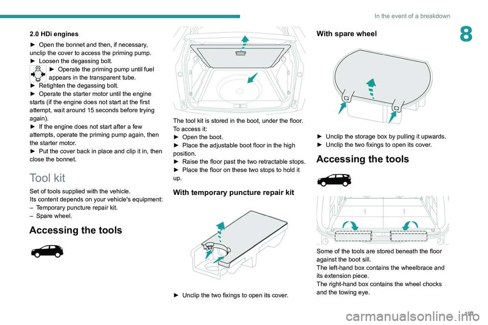
The tool kit is stored in the boot, under the floor.
To access it:
►
Open the boot.
►
Place the adjustable boot floor in the high
position.
►
Raise the floor past the two retractable stops.
►
Place the floor on these two stops to hold it
up.
With temporary puncture repair kit
► Unclip the two fixings to open its cover .
With spare wheel
► Unclip the storage box by pulling it upwards.
► Unclip the two fixings to open its cover .
Accessing the tools
Some of the tools are stored beneath the floor
against the boot sill.
The left-hand box contains the wheelbrace and
its extension piece.
The right-hand box contains the wheel chocks
and the towing eye.
Page 194 of 308
192
In the event of a breakdown
To access it:
► Open the boot.
►
Fold the concertina panels.
►
Install the third row seats.
►
Unclip the required tools from the boot sill
trim.
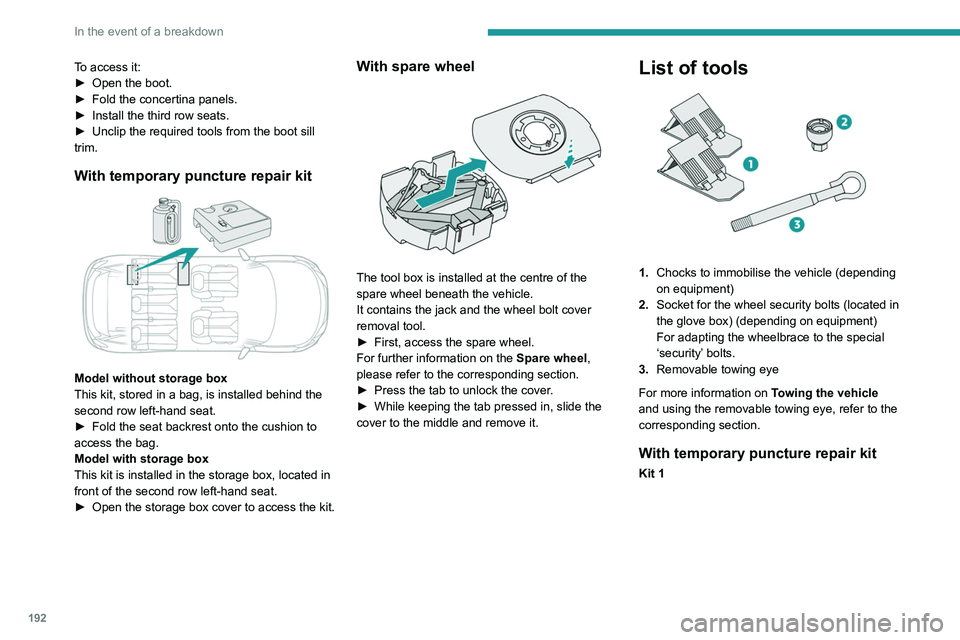
With temporary puncture repair kit
Model without storage box
This kit, stored in a bag, is installed behind the
second row left-hand seat.
►
Fold the seat backrest onto the cushion to
access the bag.
Model with storage box
This kit is installed in the storage box, located in
front of the second row left-hand seat.
►
Open the storage box cover to access the kit.
With spare wheel
The tool box is installed at the centre of the
spare wheel beneath the vehicle.
It contains the jack and the wheel bolt cover
removal tool.
►
First, access the spare wheel.
For further information on the
Spare wheel,
please refer to the corresponding section.
►
Press the tab to unlock the cover
.
►
While keeping the tab pressed in, slide the
cover to the middle and remove it.
List of tools
1. Chocks to immobilise the vehicle (depending
on equipment)
2. Socket for the wheel security bolts (located in
the glove box) (depending on equipment)
For adapting the wheelbrace to the special
‘security’ bolts.
3. Removable towing eye
For more information on Towing the vehicle
and using the removable towing eye, refer to the
corresponding section.
With temporary puncture repair kit
Kit 1
Page 195 of 308
193
In the event of a breakdown
8
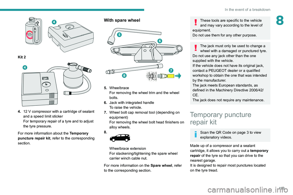
Kit 2
4.12 V compressor with a cartridge of sealant
and a speed limit sticker
For temporary repair of a tyre and to adjust
the tyre pressure.
For more information about the Temporary
puncture repair kit, refer to the corresponding
section.
With spare wheel
5. Wheelbrace
For removing the wheel trim and the wheel
bolts.
6. Jack with integrated handle
To raise the vehicle.
7. Wheel bolt cap removal tool (depending on
equipment)
For removing the wheel bolt head finishers on
alloy wheels.
8.
Wheelbrace extension
For slackening/tightening the spare wheel
carrier winch cable nut.
For more information on the Spare wheel, refer
to the corresponding section.
These tools are specific to the vehicle and may vary according to the level of
equipment.
Do not use them for any other purpose.
The jack must only be used to change a wheel with a damaged or punctured tyre.
Do not use any jack other than the one
supplied with the vehicle.
If the vehicle does not have its original jack,
contact a PEUGEOT dealer or a qualified
workshop to obtain the one that was intended
by the manufacturer.
The jack meets European standards, as
defined in the Machinery Directive 2006/42/
CE.
The jack does not require any maintenance.
Temporary puncture repair kit
Scan the QR Code on page 3 to view
explanatory videos.
Made up of a compressor and a sealant
cartridge,
it allows you to carry out a temporary
repair of the tyre so that you can drive to the
nearest garage.
It is designed to repair most punctures located
on the tyre tread.
Page 198 of 308
196
In the event of a breakdown
► Check that the compressor switch is in
position " O
".
►
Fully uncoil the electric cable stowed under
the compressor
.
►
Connect the compressor's electric plug to the
vehicle's 12
V socket.
►
Switch the ignition on.
Only the 12 V sockets located at the
front of the vehicle and in the boot can
be used to power the compressor.
The 12V socket located at the back of the
centre console is not suitable for this purpose.
The tyre inflation pressures are given on this label.
► Start the compressor by placing the switch at
position " I
" and adjust the pressure to the value
shown on the vehicle's tyre pressure label. To
deflate: press the black button located on the
compressor pipe, near the valve connection.
If after 7 minutes the pressure of 2 bar is
not reached, the tyre is damaged;
contact a PEUGEOT dealer or a qualified
workshop for assistance.
►
Once the correct pressure is reached, put the
switch in position " O
".
►
Remove the kit and stow it.
► Refit the cap on the valve.
Should the pressure of one or more tyres
be adjusted, it is necessary to reinitialise
the under-inflation detection system.
For more information on Tyre under-inflation
detection, refer to the corresponding section.
Spare wheel
Scan the QR Code on page 3 to view
explanatory videos.
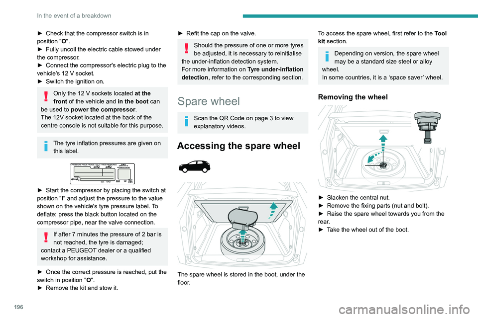
Accessing the spare wheel
The spare wheel is stored in the boot, under the
floor.
To access the spare wheel, first refer to the Tool
kit section.
Depending on version, the spare wheel
may be a standard size steel or alloy
wheel.
In some countries, it is a ‘space saver’ wheel.
Removing the wheel
► Slacken the central nut.
► Remove the fixing parts (nut and bolt).
►
Raise the spare wheel towards you from the
rear
.
►
T
ake the wheel out of the boot.
Putting the wheel back in place
► Put the wheel back in its housing.
► Slacken the nut on the bolt by a few turns.
► Position the fixing parts (nut and bolt) in the
middle of the wheel.
► Tighten fully until the central nut clicks, to
retain the wheel correctly.
► Return the tool box to the middle of the wheel
and clip it in place.
Page 199 of 308
197
In the event of a breakdown
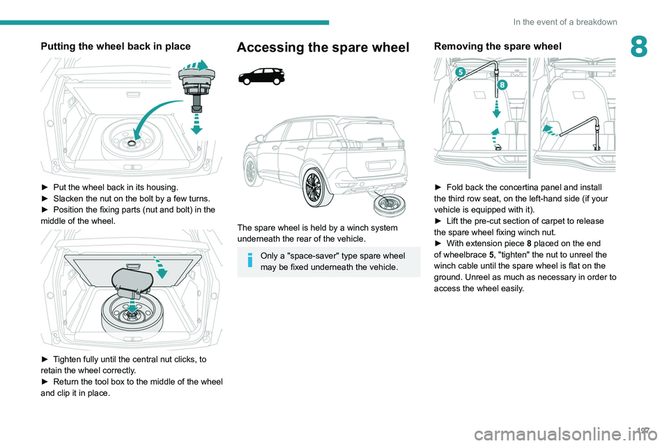
8Putting the wheel back in place
► Put the wheel back in its housing.
► Slacken the nut on the bolt by a few turns.
►
Position the fixing parts (nut and bolt) in the
middle of the wheel.
► Tighten fully until the central nut clicks, to
retain the wheel correctly.
►
Return the tool box to the middle of the wheel
and clip it in place.
Accessing the spare wheel
The spare wheel is held by a winch system
underneath the rear of the vehicle.
Only a "space-saver" type spare wheel
may be fixed underneath the vehicle.
Removing the spare wheel
► Fold back the concertina panel and install
the third row seat, on the left-hand side (if your
vehicle is equipped with it).
►
Lift the pre-cut section of carpet to release
the spare wheel
fixing winch nut.
►
With extension piece 8
placed on the end
of wheelbrace 5, "tighten" the nut to unreel the
winch cable until the spare wheel is flat on the
ground. Unreel as much as necessary in order to
access the wheel easily.
Page 200 of 308
198
In the event of a breakdown
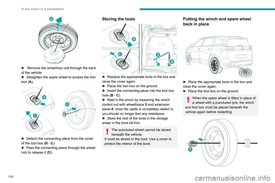
► Remove the wheel/box unit through the back
of the vehicle.
►
Straighten the spare wheel to access the tool
box (
A).
► Detach the connecting piece from the cover
of the tool box ( B - C).
►
Pass the connecting piece through the wheel
hub to release it ( D
).
Storing the tools
► Replace the appropriate tools in the box and
close the cover again.
►
Place the tool box on the ground.
►
Insert the connecting piece into the tool box
hole (
B - C).
►
Reel in the winch by loosening the winch
control nut with wheelbrace 5
and extension
piece 8: once the cable is completely reeled in,
you should no longer feel any resistance.
►
Store the rest of the tools in the storage
areas in the boot sill trim.
The punctured wheel cannot be stored beneath the vehicle.
It must be stored in the boot. Use a cover to
protect the interior of the boot.
Putting the winch and spare wheel
back in place
► Place the appropriate tools in the box and
close the cover again.
►
Place the tool box on the ground.
When the spare wheel is fitted in place of
a wheel with a punctured tyre, the winch
and tool box must be placed beneath the
vehicle again before restarting.
Page 201 of 308
199
In the event of a breakdown
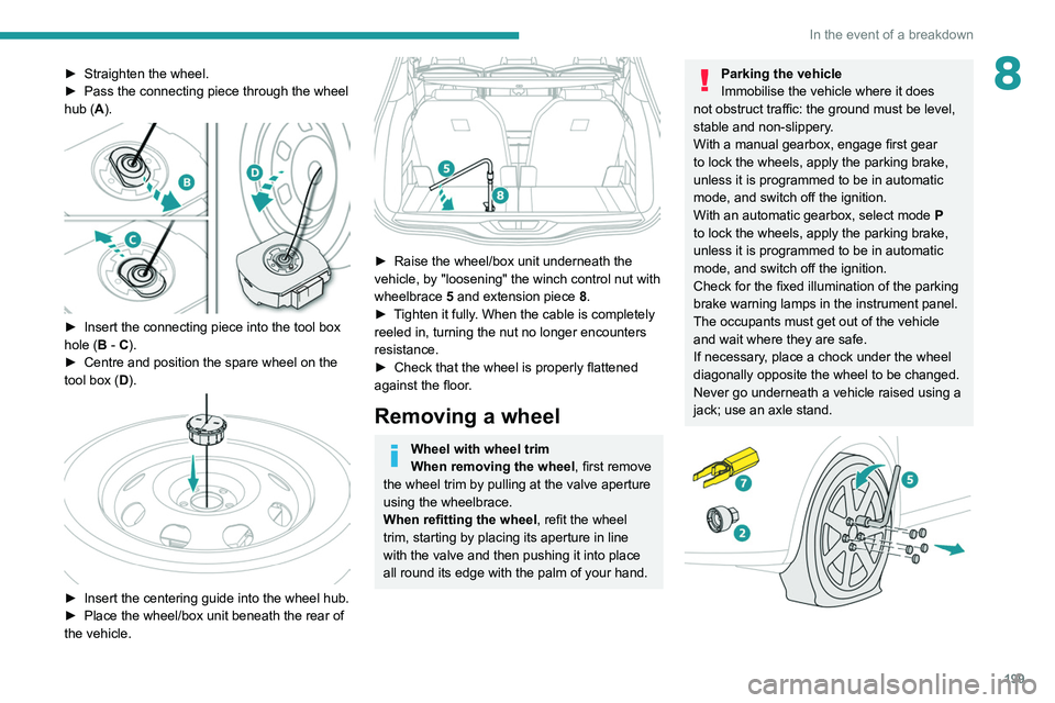
8► Straighten the wheel.
► Pass the connecting piece through the wheel
hub (
A).
► Insert the connecting piece into the tool box
hole ( B - C).
►
Centre and position the spare wheel on the
tool box (
D).
► Insert the centering guide into the wheel hub.
► Place the wheel/box unit beneath the rear of
the vehicle.
► Raise the wheel/box unit underneath the
vehicle, by "loosening" the winch control nut with
wheelbrace 5
and extension piece 8.
►
T
ighten it fully. When the cable is completely
reeled in, turning the nut no longer encounters
resistance.
►
Check that the wheel is properly flattened
against the floor
.
Removing a wheel
Wheel with wheel trim
When removing the wheel , first remove
the wheel trim by pulling at the valve aperture
using the wheelbrace.
When refitting the wheel , refit the wheel
trim, starting by placing its aperture in line
with the valve and then pushing it into place
all round its edge with the palm of your hand.
Parking the vehicle
Immobilise the vehicle where it does
not obstruct traffic: the ground must be level,
stable and non-slippery.
With a manual gearbox, engage first gear
to lock the wheels, apply the parking brake,
unless it is programmed to be in automatic
mode, and switch off the ignition.
With an automatic gearbox, select mode
P
to lock the wheels, apply the parking brake,
unless it is programmed to be in automatic
mode, and switch off the ignition.
Check for the fixed illumination of the parking
brake warning lamps in the instrument panel.
The occupants must get out of the vehicle
and wait where they are safe.
If necessary, place a chock under the wheel
diagonally opposite the wheel to be changed.
Never go underneath a vehicle raised using a
jack; use an axle stand.
Page 202 of 308

200
In the event of a breakdown
► To remove the wheel bolt cover on each of
the bolts, use tool 7 (alloy wheels).
►
Fit security socket
2 on wheelbrace
5
to
slacken the security bolt.
►
Slacken the other bolts using the
wheelbrace
5
only.
► Place the foot of jack 6 on the ground and
ensure that it is directly below the front A or
rear
B jacking point on the underbody, whichever
is closest to the wheel to be changed.
► Extend jack 6 until its head comes into
contact with jacking point A or B; contact area A
or B on the vehicle must be properly inserted
into the central part of the head of the jack.
►
Raise the vehicle until there is sufficient
space between the wheel and the ground to
admit the spare (not punctured) wheel easily
.
Ensure that the jack is stable. If the
ground is slippery or loose, the jack may
slip or collapse - risk of injury!
Take care to position the jack strictly at
one of the jacking points
A
or B under the
vehicle, ensuring that the head of the jack is
centred under the contact area of the vehicle.
Otherwise, there is a risk of damage to the
vehicle and/or of the jack collapsing - risk of
injury!
► Remove the bolts and store them in a clean
place.
►
Remove the wheel.
Fitting a wheel
Fitting a steel or ‘space-saver’ type
spare wheel
If the vehicle is equipped with alloy wheels,
the washers do not make contact with the
steel or ‘space-saver’ type spare wheel. The
wheel is secured by the conical surface of
each bolt.
► Fit the wheel on the hub.
► Screw in the bolts by hand as far as possible.
►
Pre-tighten the security bolt using the
wheelbrace
5
equipped with a security socket
2
.
►
Pre-tighten the other bolts using the
wheelbrace
5
only.