2020 PEUGEOT 5008 ESP
[x] Cancel search: ESPPage 187 of 308
185
Practical information
7AdBlue® (BlueHDi)
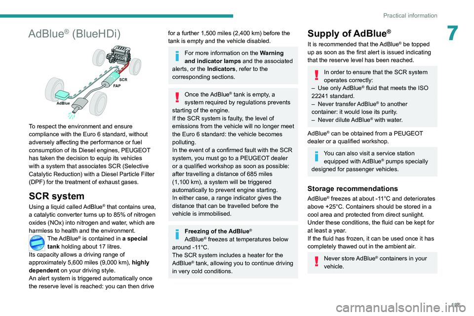
To respect the environment and ensure
compliance with the Euro 6 standard, without
adversely affecting the performance or fuel
consumption of its Diesel engines, PEUGEOT
has taken the decision to equip its vehicles
with a system that associates SCR (Selective
Catalytic Reduction) with a Diesel Particle Filter
(DPF) for the treatment of exhaust gases.
SCR system
Using a liquid called AdBlue® that contains urea,
a catalytic converter turns up to 85% of nitrogen
oxides (NOx) into nitrogen and water, which are
harmless to health and the environment.
The AdBlue® is contained in a special
tank holding about 17 litres.
Its capacity allows a driving range of
approximately 5,600
miles (9,000 km), highly
dependent on your driving style.
An alert system is triggered automatically once
the reserve level is reached: you can then drive
for a further 1,500 miles (2,400 km) before the
tank is empty and the vehicle disabled.
For more information on the Warning
and indicator lamps and the associated
alerts, or the Indicators, refer to the
corresponding sections.
Once the AdBlue® tank is empty, a
system required by regulations prevents
starting of the engine.
If the SCR system is faulty
, the level of
emissions from the vehicle will no longer meet
the Euro 6 standard: the vehicle becomes
polluting.
In the event of a confirmed fault with the SCR
system, you must go to a PEUGEOT dealer
or a qualified workshop as soon as possible:
after travelling a distance of 685
miles
(1,100
km), a system will be triggered
automatically to prevent engine starting.
In either case, a range indicator gives the
distance that can be travelled before the
vehicle is immobilised.
Freezing of the AdBlue®
AdBlue® freezes at temperatures below
around -11°C.
The SCR system includes a heater for the
AdBlue
® tank, allowing you to continue driving
in very cold conditions.
Supply of AdBlue®
It is recommended that the AdBlue® be topped
up as soon as the first alert is issued indicating
that the reserve level has been reached.
In order to ensure that the SCR system
operates correctly:
–
Use
only AdBlue
® fluid that meets the ISO
22241 standard.
–
Never
transfer AdBlue
® to another
container: it would lose its purity.
–
Never
dilute AdBlue
® with water.
AdBlue
® can be obtained from a PEUGEOT
dealer or a qualified workshop.
You can also visit a service station equipped with AdBlue® pumps specially
designed for passenger vehicles.
Storage recommendations
AdBlue® freezes at about -11°C and deteriorates
above +25°C. Containers should be stored in a
cool area and protected from direct sunlight.
Under these conditions, the fluid can be kept for
at least a year.
If the fluid has frozen, it can be used once it has
completely thawed out in the ambient air.
Never store AdBlue® containers in your
vehicle.
Page 192 of 308
190
In the event of a breakdown
Warning triangle
As a safety precaution, before leaving your
vehicle to set up and install the triangle, switch
on the hazard warning lamps and put on your
high visibility vest.
Storage compartment
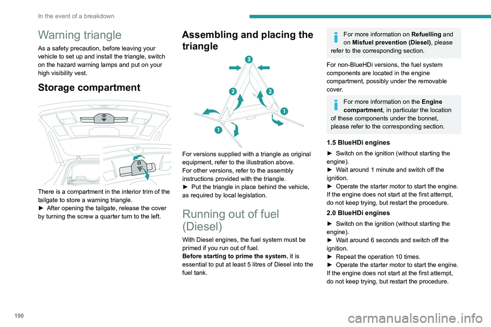
There is a compartment in the interior trim of the
tailgate to store a warning triangle.
►
After opening the tailgate, release the cover
by turning the screw a quarter turn to the left.
Assembling and placing the triangle
For versions supplied with a triangle as original
equipment, refer to the illustration above.
For other versions, refer to the assembly
instructions provided with the triangle.
►
Put the triangle in place behind the vehicle,
as required by local legislation.
Running out of fuel
(Diesel)
With Diesel engines, the fuel system must be
primed if you run out of fuel.
Before starting to prime the system, it is
essential to put at least 5 litres of Diesel into the
fuel tank.
For more information on Refuelling and
on Misfuel prevention (Diesel), please
refer to the corresponding section.
For non-BlueHDi versions, the fuel system
components are located in the engine
compartment, possibly under the removable
cover.
For more information on the Engine
compartment, in particular the location
of these components under the bonnet,
please refer to the corresponding section.
1.5 BlueHDi engines
► Switch on the ignition (without starting the
engine).
►
W
ait around 1 minute and switch off the
ignition.
►
Operate the starter motor to start the engine.
If the engine does not start at the first attempt,
do not keep trying, but restart the procedure.
2.0 BlueHDi engines
► Switch on the ignition (without starting the
engine).
►
W
ait around 6 seconds and switch off the
ignition.
►
Repeat the operation 10
times.
►
Operate the starter motor to start the engine.
If the engine does not start at the first attempt,
do not keep trying, but restart the procedure.
2.0 HDi engines
► Open the bonnet and then, if necessary,
unclip the cover to access the priming pump.
► Loosen the degassing bolt.
► Operate the priming pump until fuel
appears in the transparent tube.
► Retighten the degassing bolt.
► Operate the starter motor until the engine
starts (if the engine does not start at the first
attempt, wait around 15 seconds before trying
again).
► If the engine does not start after a few
attempts, operate the priming pump again, then
the starter motor.
► Put the cover back in place and clip it in, then
close the bonnet.
Tool kit
Set of tools supplied with the vehicle.
Its content depends on your vehicle's equipment:
– Temporary puncture repair kit.
– Spare wheel.
Accessing the tools
Page 194 of 308
192
In the event of a breakdown
To access it:
► Open the boot.
►
Fold the concertina panels.
►
Install the third row seats.
►
Unclip the required tools from the boot sill
trim.
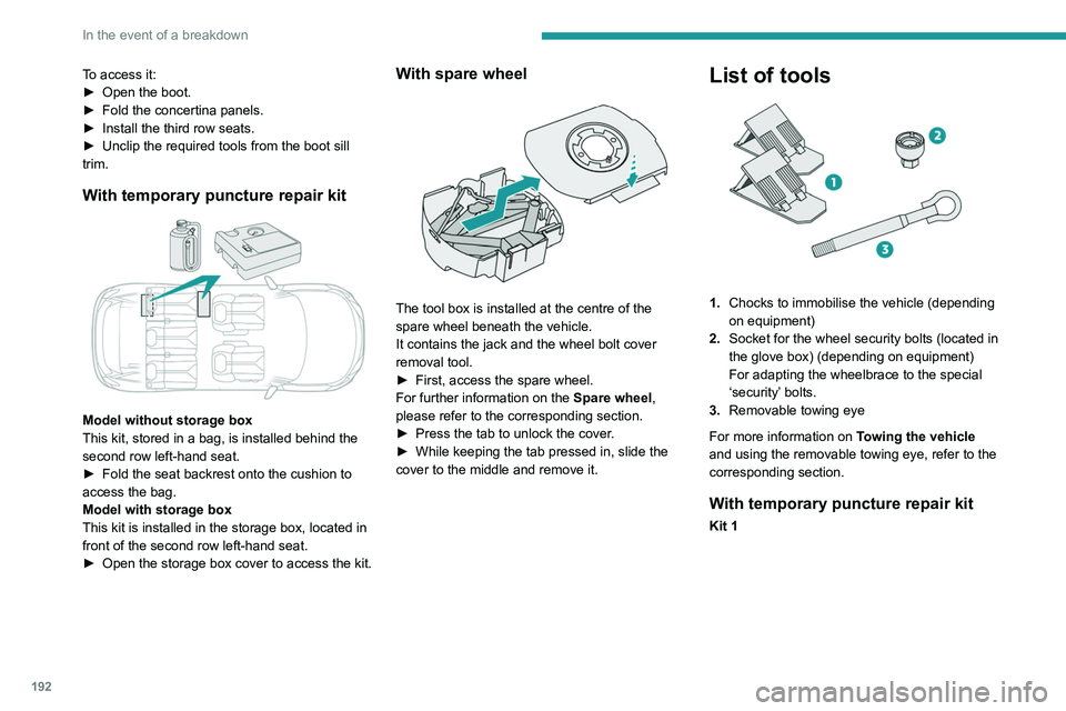
With temporary puncture repair kit
Model without storage box
This kit, stored in a bag, is installed behind the
second row left-hand seat.
►
Fold the seat backrest onto the cushion to
access the bag.
Model with storage box
This kit is installed in the storage box, located in
front of the second row left-hand seat.
►
Open the storage box cover to access the kit.
With spare wheel
The tool box is installed at the centre of the
spare wheel beneath the vehicle.
It contains the jack and the wheel bolt cover
removal tool.
►
First, access the spare wheel.
For further information on the
Spare wheel,
please refer to the corresponding section.
►
Press the tab to unlock the cover
.
►
While keeping the tab pressed in, slide the
cover to the middle and remove it.
List of tools
1. Chocks to immobilise the vehicle (depending
on equipment)
2. Socket for the wheel security bolts (located in
the glove box) (depending on equipment)
For adapting the wheelbrace to the special
‘security’ bolts.
3. Removable towing eye
For more information on Towing the vehicle
and using the removable towing eye, refer to the
corresponding section.
With temporary puncture repair kit
Kit 1
Page 195 of 308
193
In the event of a breakdown
8
Kit 2
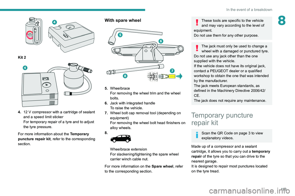
4.12 V compressor with a cartridge of sealant
and a speed limit sticker
For temporary repair of a tyre and to adjust
the tyre pressure.
For more information about the Temporary
puncture repair kit, refer to the corresponding
section.
With spare wheel
5. Wheelbrace
For removing the wheel trim and the wheel
bolts.
6. Jack with integrated handle
To raise the vehicle.
7. Wheel bolt cap removal tool (depending on
equipment)
For removing the wheel bolt head finishers on
alloy wheels.
8.
Wheelbrace extension
For slackening/tightening the spare wheel
carrier winch cable nut.
For more information on the Spare wheel, refer
to the corresponding section.
These tools are specific to the vehicle and may vary according to the level of
equipment.
Do not use them for any other purpose.
The jack must only be used to change a wheel with a damaged or punctured tyre.
Do not use any jack other than the one
supplied with the vehicle.
If the vehicle does not have its original jack,
contact a PEUGEOT dealer or a qualified
workshop to obtain the one that was intended
by the manufacturer.
The jack meets European standards, as
defined in the Machinery Directive 2006/42/
CE.
The jack does not require any maintenance.
Temporary puncture repair kit
Scan the QR Code on page 3 to view
explanatory videos.
Made up of a compressor and a sealant
cartridge,
it allows you to carry out a temporary
repair of the tyre so that you can drive to the
nearest garage.
It is designed to repair most punctures located
on the tyre tread.
Page 198 of 308
196
In the event of a breakdown
► Check that the compressor switch is in
position " O
".
►
Fully uncoil the electric cable stowed under
the compressor
.
►
Connect the compressor's electric plug to the
vehicle's 12
V socket.
►
Switch the ignition on.
Only the 12 V sockets located at the
front of the vehicle and in the boot can
be used to power the compressor.
The 12V socket located at the back of the
centre console is not suitable for this purpose.
The tyre inflation pressures are given on this label.
► Start the compressor by placing the switch at
position " I
" and adjust the pressure to the value
shown on the vehicle's tyre pressure label. To
deflate: press the black button located on the
compressor pipe, near the valve connection.
If after 7 minutes the pressure of 2 bar is
not reached, the tyre is damaged;
contact a PEUGEOT dealer or a qualified
workshop for assistance.
►
Once the correct pressure is reached, put the
switch in position " O
".
►
Remove the kit and stow it.
► Refit the cap on the valve.
Should the pressure of one or more tyres
be adjusted, it is necessary to reinitialise
the under-inflation detection system.
For more information on Tyre under-inflation
detection, refer to the corresponding section.
Spare wheel
Scan the QR Code on page 3 to view
explanatory videos.
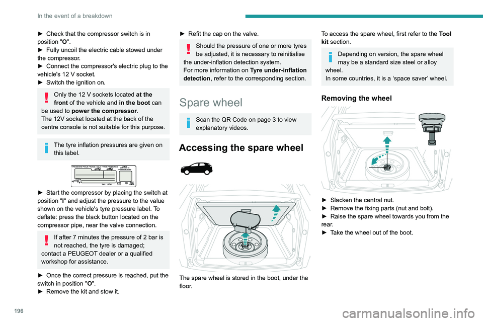
Accessing the spare wheel
The spare wheel is stored in the boot, under the
floor.
To access the spare wheel, first refer to the Tool
kit section.
Depending on version, the spare wheel
may be a standard size steel or alloy
wheel.
In some countries, it is a ‘space saver’ wheel.
Removing the wheel
► Slacken the central nut.
► Remove the fixing parts (nut and bolt).
►
Raise the spare wheel towards you from the
rear
.
►
T
ake the wheel out of the boot.
Putting the wheel back in place
► Put the wheel back in its housing.
► Slacken the nut on the bolt by a few turns.
► Position the fixing parts (nut and bolt) in the
middle of the wheel.
► Tighten fully until the central nut clicks, to
retain the wheel correctly.
► Return the tool box to the middle of the wheel
and clip it in place.
Page 204 of 308
202
In the event of a breakdown
Always replace a failed bulb with a new bulb
of the same type and specification. To avoid
lighting imbalance, replace the bulbs in pairs.
Refitting the lamp units
Perform the operations in the reverse
order to dismantling.
Light-emitting diode (LED)
headlamps and lamps
Depending on version, the affected types of
headlamps / lamps are:
–
Full LED technology headlamps.
–
Direction indicator side repeaters.
–
Side spotlamps.
–
Third brake lamp.
For the replacement of this type of bulb,
you must contact a PEUGEOT dealer or
a qualified workshop.
Do not touch the "Full LED" technology
headlamps - risk of electrocution!
Front lamps
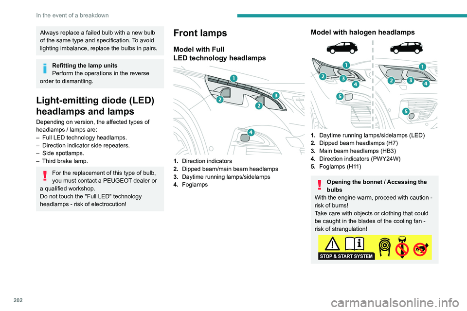
Model with Full
LED technology headlamps
1.Direction indicators
2. Dipped beam/main beam headlamps
3. Daytime running lamps/sidelamps
4. Foglamps
Model with halogen headlamps
1.Daytime running lamps/sidelamps (LED)
2. Dipped beam headlamps (H7)
3. Main beam headlamps (HB3)
4. Direction indicators (PWY24W)
5. Foglamps (H11)
Opening the bonnet / Accessing the
bulbs
With the engine warm, proceed with caution -
risk of burns!
Take care with objects or clothing that could
be caught in the blades of the cooling fan -
risk of strangulation!
Halogen bulbs (Hx)
To ensure good quality lighting, check
that the bulb is correctly positioned in its
housing.
Direction indicators
Rapid flashing of a direction indicator
lamp (left or right) indicates that one of
the bulbs on the corresponding side has
failed.
► Turn the connector a quarter turn
anti-clockwise.
► Pull the bulb connector.
► Remove the bulb and replace it.
Amber coloured bulbs must be replaced
by bulbs with identical specifications and
colour.
Page 205 of 308
203
In the event of a breakdown
8Halogen bulbs (Hx)
To ensure good quality lighting, check
that the bulb is correctly positioned in its
housing.
Direction indicators
Rapid flashing of a direction indicator
lamp (left or right) indicates that one of
the bulbs on the corresponding side has
failed.
► Turn the connector a quarter turn
anti-clockwise.
►
Pull the bulb connector
.
►
Remove the bulb and replace it.
Amber coloured bulbs must be replaced by bulbs with identical specifications and
colour.
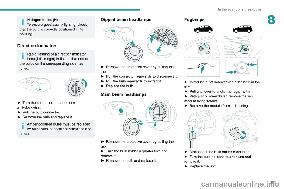
Dipped beam headlamps
► Remove the protective cover by pulling the
tab.
►
Pull the connector rearwards to disconnect it.
►
Pull the bulb rearwards to extract it.
►
Replace the bulb.
Main beam headlamps
► Remove the protective cover by pulling the
tab.
►
T
urn the bulb holder a quarter turn and
remove it.
►
Remove the bulb and replace it.
Foglamps
► Introduce a flat screwdriver in the hole in the
trim.
►
Pull and lever to unclip the foglamp trim.
►
With a
Torx screwdriver, remove the two
module fixing screws.
►
Remove the module from its housing.
► Disconnect the bulb holder connector .
► T urn the bulb holder a quarter turn and
remove it.
►
Replace the unit.
Page 208 of 308

206
In the event of a breakdown
► Open the glove box.
► Press on the central handle of the fusebox
cover
.
►
Lower the cover completely
.
►
T
ake the tweezers from their housing.
Changing a fuse
Before changing a fuse:
► Identify the cause of the fault and fix it.
►
Stop all power consumption.
►
Immobilise the vehicle and switch the ignition
off.
►
Identify the defective fuse using the current
allocation tables and diagrams.
T
o replace a fuse, it is essential to:
►
Use the special tweezers to extract the fuse
from its housing and check the condition of its
filament.
►
Always replace the failed fuse with a fuse of
the same rating (same colour); use of a different
rating may cause malfunctions - risk of fire!
If the fault recurs after replacing a fuse, have
the electrical system checked by a PEUGEOT
dealer or a qualified workshop.
The fuse allocation tables and the corresponding diagrams are available
from a PEUGEOT dealer or from a qualified
workshop.
The replacement of a fuse not shown in the allocation tables may cause a serious
malfunction of your vehicle. Contact a
PEUGEOT dealer or a qualified workshop.
Good
Failed
Tweezers
Installing electrical accessories
Your vehicle's electrical system is
designed to operate with standard or optional
equipment.
Before installing other electrical equipment
or accessories on your vehicle, contact a
PEUGEOT dealer or a qualified workshop.
PEUGEOT accepts no responsibility for
the cost incurred in repairing your vehicle
or for rectifying malfunctions resulting from
the installation of accessories not supplied
and not recommended by PEUGEOT and not
installed in accordance with specifications, in
particular when the combined power
consumption of all of the additional equipment
connected exceeds 10 milliamperes.
Fuses in the dashboard
The fusebox is located in the lower dashboard
(left-hand side).
To access the fuses, follow the same procedure
as described for accessing the fuse replacement
tools.
Version 1 (Full)
Box 1
Fuse N° Rating (A)Functions
F1 3 AKeyless Entry and Starting.
F2 5 AMultifunction screen.
F5 5 AReversing camera - Parking sensors.
F7 10 AHi-Fi amplifier.
F8 20 ARear wiper.
F10 30 ALocks.
F 11 30 ALocks.
F17 10 ABoot 12 V accessory socket.
F18 5 AEmergency and assistance calls.
F22 3 AGlove box lighting.
F26 3 ASeat belts not fastened warning lamps display.
F27 3 ARain/sunshine sensor.
F31 5 AAirbags.
F33 15 AFront 12 V accessory socket.
F35 5 AInstrument panel.
F36 20 AAudio system - Touch screen - CD player - Audio/navigation system.
Box 2 Fuse N° Rating (A)Functions
F17 10 AMemorising driving positions.