2020 NISSAN SENTRA ignition
[x] Cancel search: ignitionPage 403 of 528
When the vehicle information display is
used to turn off the VDC system, the sys-
tem still operates to prevent one drive
wheel from slipping by transferring power
to a non-slipping drive wheel. The
indicator light flashes if this occurs. All
other VDC functions are off and the
indicator light will not flash.
The VDC system is automatically reset to
on when the ignition switch is placed in the
OFF position then back to the ON position.
The computer has a built-in diagnostic fea-
ture that tests the system each time you
start the engine and move the vehicle for-
ward or in reverse at a slow speed. When
the self-test occurs, you may hear a clunk
noise and/or feel a pulsation in the brake
pedal. This is normal and is not an indica-
tion of a malfunction.
WARNING
• The VDC system is designed to help
the driver maintain stability but does
not prevent accidents due to abrupt
steering operation at high speeds or
by careless or dangerous driving
techniques. Reduce vehicle speed
and be especially careful when driv-
ing and cornering on slippery sur-
faces and always drive carefully.
• Do not modif y the vehicle's suspen-
sion. If suspension parts such as
shock absorbers, struts, springs, sta-
bilizer bars, bushings and wheels are
not NISSAN recommended for your
vehicle or are extremely deterio-
rated, the VDC system may not oper-
ate properly. This could adversely af-
fect vehicle handling performance,
and the
indicator light may flash
or theindicator light may
illuminate.
• If brake related parts such as brake
pads, rotors and calipers are not
NISSAN recommended or are ex-
tremely deteriorated, the VDC sys-
tem may not operate properly and
the
indicator light may
illuminate. •
If engine control related parts are not
NISSAN recommended or are ex-
tremely deteriorated, the
indica-
tor light may illuminate.
• When driving on extremely inclined
surfaces such as higher banked cor-
ners, the VDC system may not oper-
ate properly and the
indicator
light may flash or theindicator
light may illuminate. Do not drive on
these types of roads.
• When driving on an unstable surface
such as a turntable, ferry, elevator or
ramp, the
indicator light may
flash or theindicator light may
illuminate. This is not a malfunction.
Restart the engine af ter driving onto
a stable surface.
• If wheels or tires other than the
NISSAN recommended ones are
used, the VDC system may not oper-
ate properly and the
indicator
light may flash or theindicator
light may illuminate.
• The VDC system is not a substitute
for winter tires or tire chains on a
snow covered road.
Starting and driving5-117
Page 409 of 528
The system is automatically activated
when the ignition is in the ON position and
the shif t lever is in the R (Reverse) position.
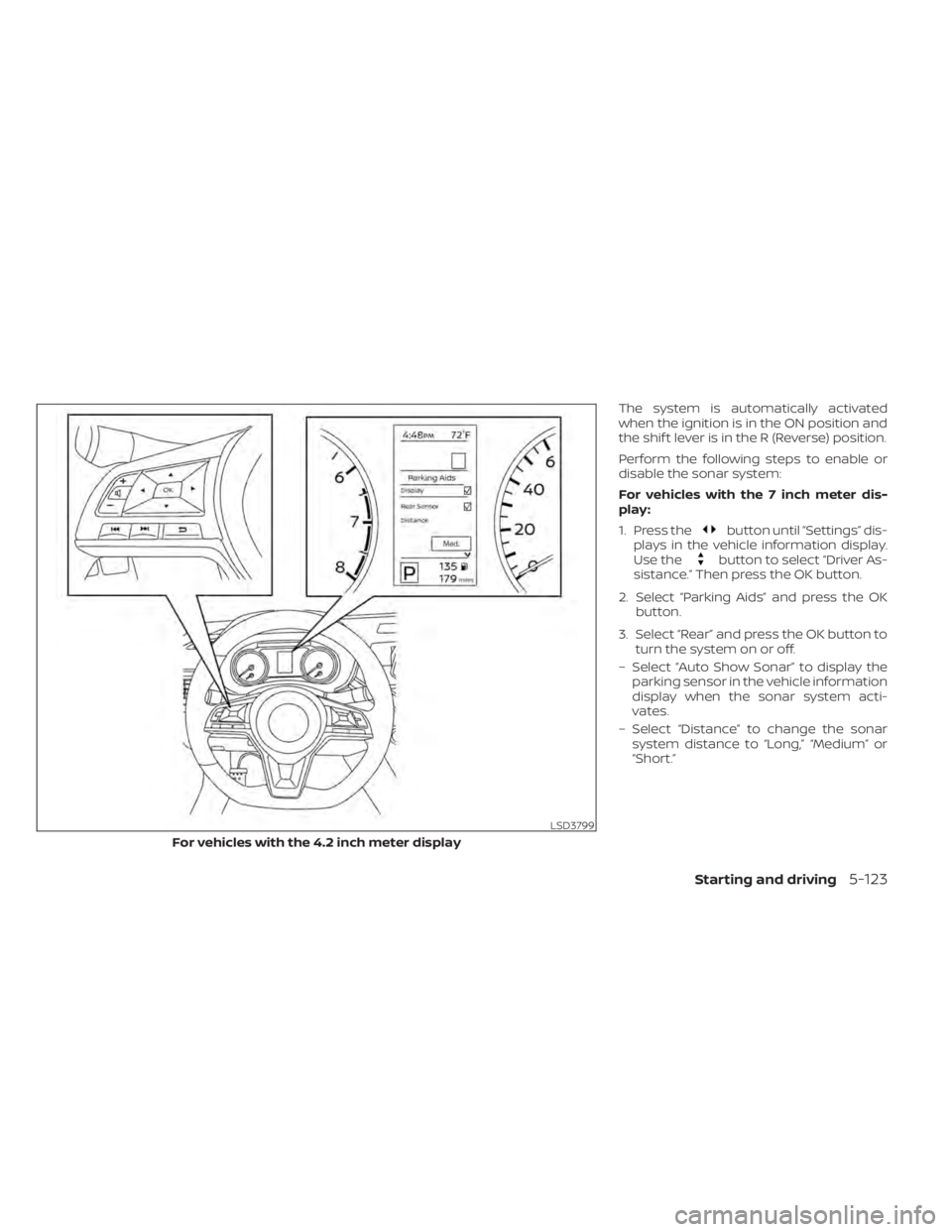
Perform the following steps to enable or
disable the sonar system:
For vehicles with the 7 inch meter dis-
play:
1. Press the
button until “Settings” dis-
plays in the vehicle information display.
Use the
button to select “Driver As-
sistance.” Then press the OK button.
2. Select “Parking Aids” and press the OK button.
3. Select “Rear” and press the OK button to turn the system on or off.
– Select “Auto Show Sonar” to display the parking sensor in the vehicle information
display when the sonar system acti-
vates.
– Select “Distance” to change the sonar system distance to “Long,” “Medium” or
“Short.”
LSD3799
For vehicles with the 4.2 inch meter display
Starting and driving5-123
Page 416 of 528
Push the switch on to warn other drivers
when you must stop or park under emer-
gency conditions. All turn signal lights flash.
WARNING
• If stopping for an emergency, be sure
to move the vehicle well off the road.
• Do not use the hazard warning flash-
ers while moving on the highway un-
less unusual circumstances force
you to drive so slowly that your ve-
hicle might become a hazard to other
traffic.
• Turn signals do not work when the
hazard warning flasher lights are on.
The flashers will operate with the ignition
switch placed in any position.
Some jurisdictions may prohibit the use
of the hazard warning flasher switch
while driving. To shut off the engine in an emergency
situation while driving, perform the follow-
ing procedure:
• Rapidly push the push-button ignition
switch three consecutive times in less
than 1.5 seconds, or
• Push and hold the push-button ignition switch for more than 2 seconds.
LIC0394
HAZARD WARNING FLASHER SWITCH EMERGENCY ENGINE SHUT OFF
6-2In case of emergency
Page 424 of 528
WARNING
Always follow the instructions below.
Failure to do so could result in damage
to the charging system and cause per-
sonal injury.
1. If the booster battery is in another ve- hicle, position the two vehicles to bring
their batteries near each other.
Do not allow the two vehicles to touch. 2. Apply the parking brake. Move the shif t
lever to N (Neutral) (manual transmis-
sion) or to P (Park) (Continuously Variable
Transmission (CVT)). Switch off all un-
necessary electrical systems (lights,
heater, air conditioner, etc.).
3. Place the ignition switch to the LOCK or OFF position.
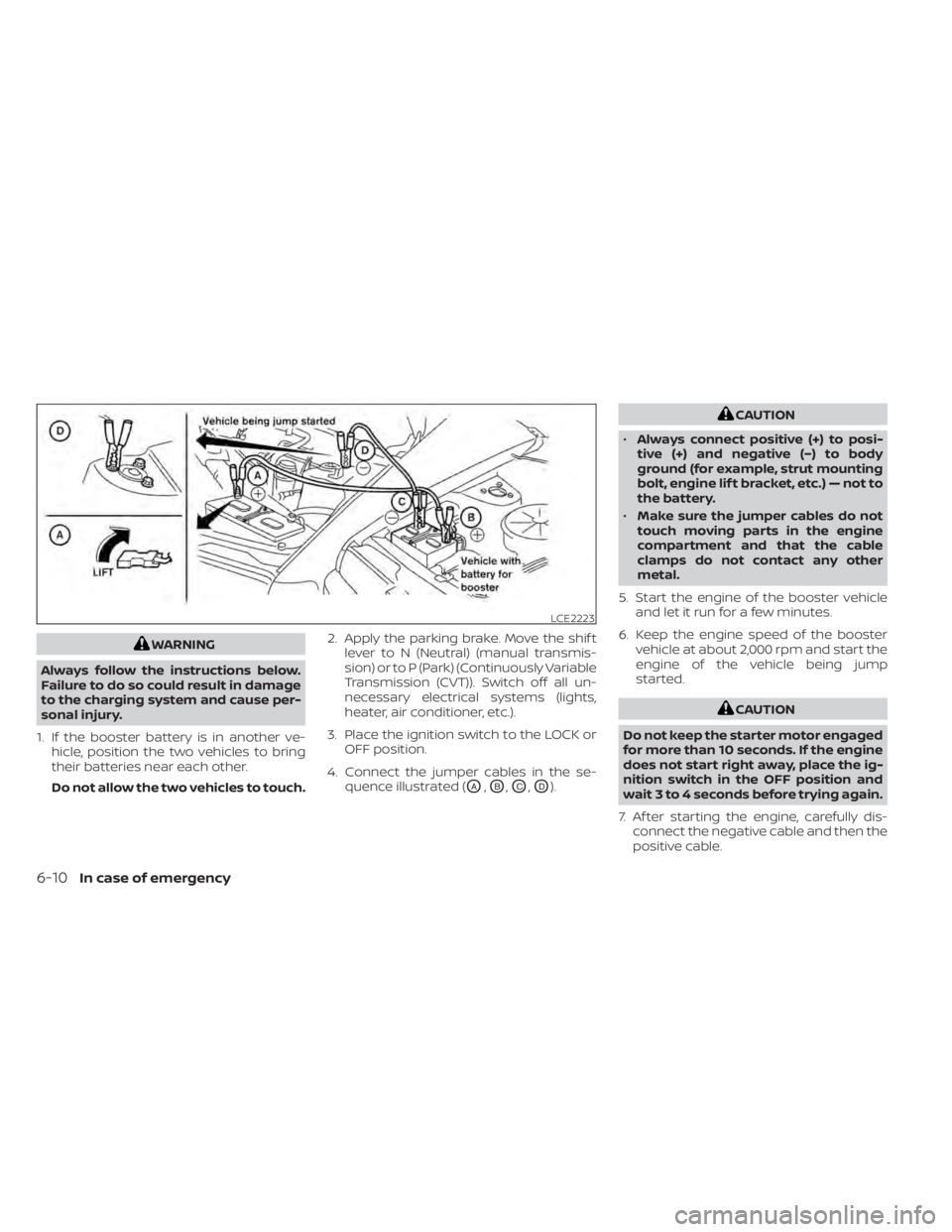
4. Connect the jumper cables in the se- quence illustrated (
OA,OB,OC,OD).
CAUTION
• Always connect positive (+) to posi-
tive (+) and negative (−) to body
ground (for example, strut mounting
bolt, engine lif t bracket, etc.) — not to
the battery.
• Make sure the jumper cables do not
touch moving parts in the engine
compartment and that the cable
clamps do not contact any other
metal.
5. Start the engine of the booster vehicle and let it run for a few minutes.
6. Keep the engine speed of the booster vehicle at about 2,000 rpm and start the
engine of the vehicle being jump
started.
CAUTION
Do not keep the starter motor engaged
for more than 10 seconds. If the engine
does not start right away, place the ig-
nition switch in the OFF position and
wait 3 to 4 seconds before trying again.
7. Af ter starting the engine, carefully dis- connect the negative cable and then the
positive cable.
LCE2223
6-10In case of emergency
Page 427 of 528
Two-Wheel Drive models with
Continuously Variable
Transmission (CVT)
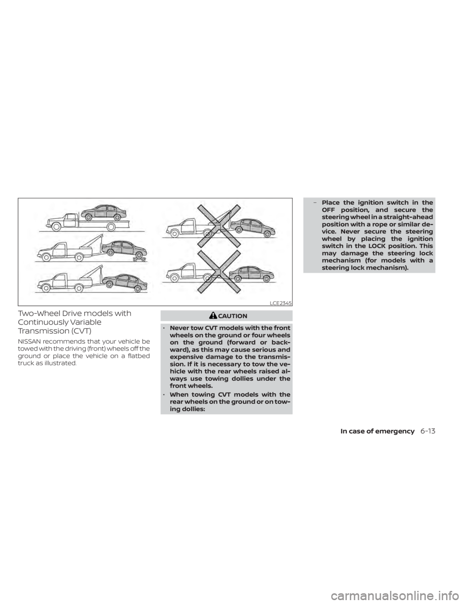
NISSAN recommends that your vehicle be
towed with the driving (front) wheels off the
ground or place the vehicle on a flatbed
truck as illustrated.
CAUTION
• Never tow CVT models with the front
wheels on the ground or four wheels
on the ground (forward or back-
ward), as this may cause serious and
expensive damage to the transmis-
sion. If it is necessary to tow the ve-
hicle with the rear wheels raised al-
ways use towing dollies under the
front wheels.
• When towing CVT models with the
rear wheels on the ground or on tow-
ing dollies: –
Place the ignition switch in the
OFF position, and secure the
steering wheel in a straight-ahead
position with a rope or similar de-
vice. Never secure the steering
wheel by placing the ignition
switch in the LOCK position. This
may damage the steering lock
mechanism (for models with a
steering lock mechanism).
LCE2345
In case of emergency6-13
Page 437 of 528
When installing Genuine NISSAN floor mats,
follow the installation instructions provided
with the mat and the following:
1. With the ignition in the OFF position, theshif t lever in P (Park) position (Continu-
ously Variable Transmission models) or
the shif t lever in the N (Neutral) position
(manual transmission models) and with
the parking break fully applied, position
the floor mat in the floorwell so that the
floor mat grommet holes are aligned
with the hook(s).
2. Secure the grommet holes into the hook(s) and ensure that the floor mat is
properly positioned.
3. Make sure the floor mat does not inter- fere with pedal operation. With the igni-
tion still in the OFF position, the shif t le-
ver in the P (Park) position (Continuously
Variable Transmission models) or the
shif t lever in the N (Neutral) position
(manual transmission models) and with
the parking break applied, fully apply
and release all pedals. The floor mat
must not interfere with pedal operation
or prevent the pedal from returning to
its normal position. It is recommended that you visit a NISSAN
dealer for details about installing the floor
mats in your vehicle.
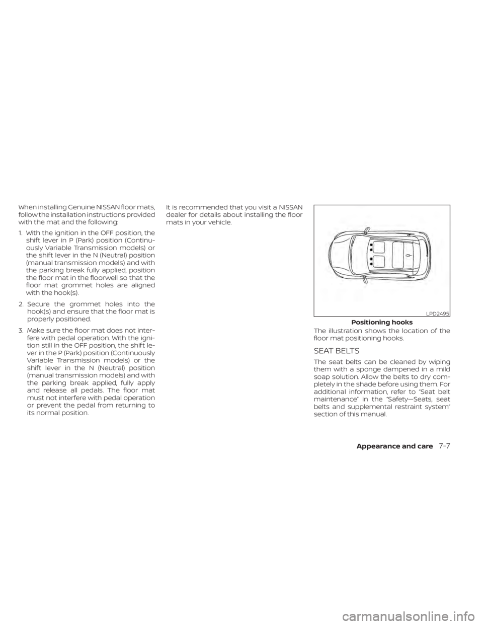
The illustration shows the location of the
floor mat positioning hooks.
SEAT BELTS
The seat belts can be cleaned by wiping
them with a sponge dampened in a mild
soap solution. Allow the belts to dry com-
pletely in the shade before using them. For
additional information, refer to “Seat belt
maintenance” in the “Safety—Seats, seat
belts and supplemental restraint system”
section of this manual.
LPD2495
Positioning hooks
Appearance and care7-7
Page 442 of 528
When performing any inspection or main-
tenance work on your vehicle, always take
care to prevent serious accidental injury to
yourself or damage to the vehicle. The fol-
lowing are general precautions which
should be closely observed.
WARNING
• Park the vehicle on a level surface,
apply the parking brake securely and
block the wheels to prevent the ve-
hicle from moving. For manual trans-
mission models, move the shif t lever
to N (Neutral). For CVT models, move
the shif t lever to P (Park).
• Be sure the ignition switch is in the
OFF or LOCK position when perform-
ing any parts replacement or repairs.
• If you must work with the engine run-
ning, keep your hands, clothing, hair
and tools away from moving fans,
belts and any other moving parts.
• It is advisable to secure or remove
any loose clothing and remove any
jewelry, such as rings, watches, etc.
before working on your vehicle.
• Always wear eye protection when-
ever you work on your vehicle. •
If you must run the engine in an en-
closed space such as a garage, be
sure there is proper ventilation for
exhaust gases to escape.
• Never get under the vehicle while it is
supported only by a jack. If it is nec-
essary to work under the vehicle,
support it with safety stands.
• Keep smoking materials, flame and
sparks away from the fuel tank and
battery.
• Because the fuel lines on gasoline
engine models are under high pres-
sure even when the engine is off, it is
recommended that you visit a
NISSAN dealer for service of the fuel
filter or fuel lines.
• Your vehicle is equipped with an au-
tomatic engine cooling fan. It may
come on at any time without warn-
ing, even if the ignition key is in the
OFF position and the engine is not
running. To avoid injury, always dis-
connect the negative battery cable
before working near the fan.
CAUTION
• Do not work under the hood while
the engine is hot. Turn the engine off
and wait until it cools down.
• Avoid contact with used engine oil
and coolant. Improperly disposed
engine oil, engine coolant and/or
other vehicle fluids can damage the
environment. Always conform to lo-
cal regulations for disposal of vehicle
fluid.
• Never leave the engine or the trans-
mission related component harness
connector disconnected while the ig-
nition switch is in the ON position.
• Never connect or disconnect the bat-
tery or any transistorized compo-
nent while the ignition switch is in
the ON position.
This “Do-it-yourself ” section gives instruc-
tions regarding only those items which are
relatively easy for an owner to perform.
A Genuine NISSAN service manual is also
available. For additional information, refer
to “Owner's Manual/Service Manual order
information” in the “Technical and con-
sumer information” section of this manual.
MAINTENANCE PRECAUTIONS
8-2Do-it-yourself
Page 454 of 528
CAUTION
• Do not ground accessories directly to
the battery terminal. Doing so will
bypass the variable voltage control
system and the vehicle battery may
not charge completely.
• Use electrical accessories with the
engine running to avoid discharging
the vehicle battery. Your vehicle is equipped with a variable
voltage control system. This system mea-
sures the amount of electrical discharge
from the battery and controls voltage gen-
erated by the generator.
The current sensor
OAis located near the
battery along the negative battery cable. If
you add electrical accessories to your ve-
hicle, be sure to ground them to a suitable
body ground such as the frame or engine
block area.
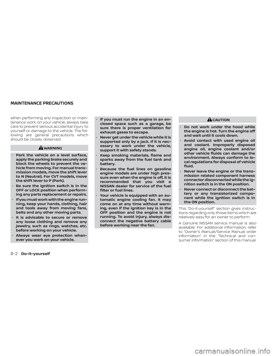
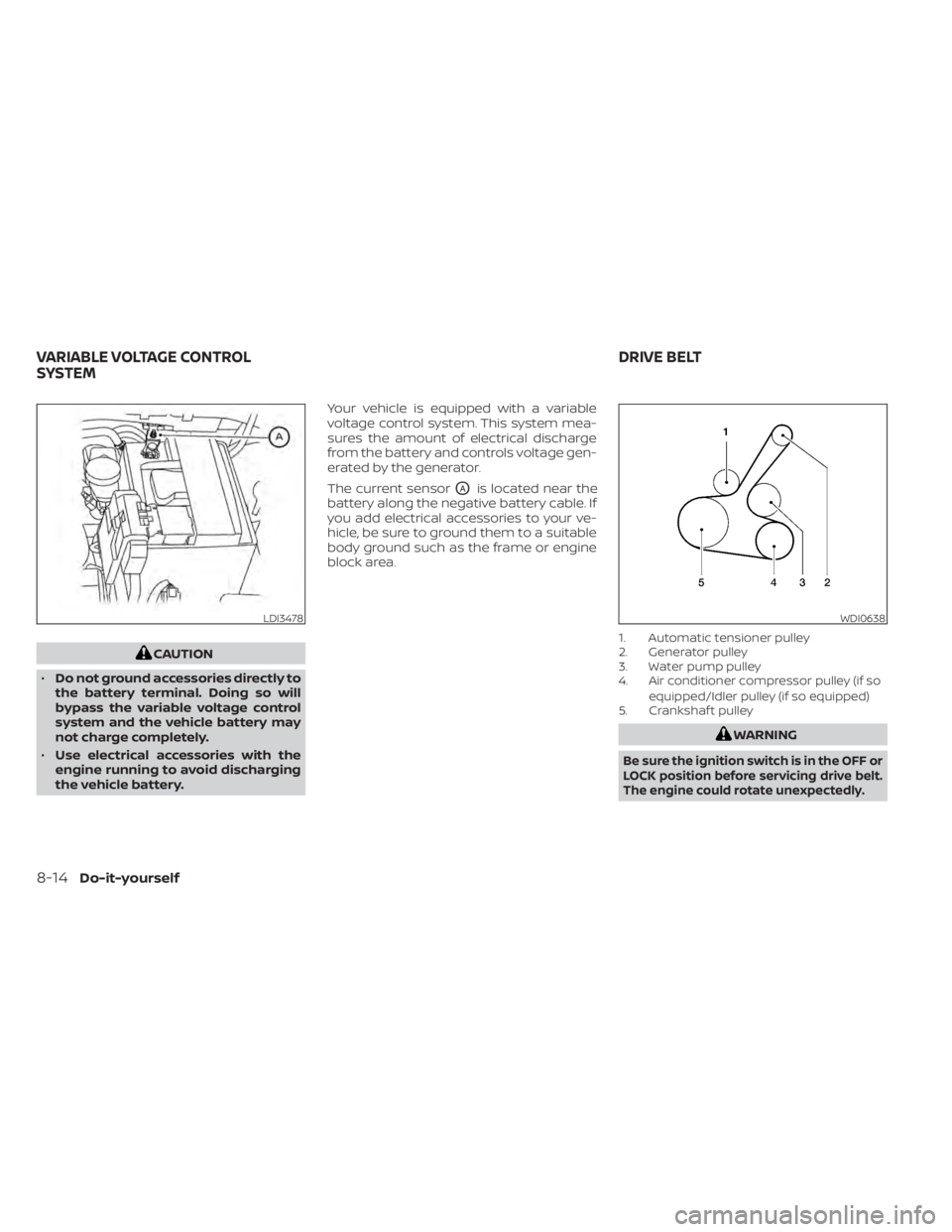
1. Automatic tensioner pulley
2. Generator pulley
3. Water pump pulley
4. Air conditioner compressor pulley (if so
equipped/Idler pulley (if so equipped)
5. Crankshaf t pulley
WARNING
Be sure the ignition switch is in the OFF or
LOCK position before servicing drive belt.
The engine could rotate unexpectedly.
LDI3478WDI0638
VARIABLE VOLTAGE CONTROL
SYSTEM DRIVE BELT
8-14Do-it-yourself