2020 MERCEDES-BENZ GLS SUV ECU
[x] Cancel search: ECUPage 377 of 549
Re
moving the fire extinguisher &
WARNING Risk of accident due toan
incor rectly secu redfire extinguisher in
th e driver's foot we ll
A fire extinguisher may impede pedal tr avel
or block a depressed pedal.
This jeopardises the operating and road
saf ety of theve hicle.
The fire extinguisher can be flung around and
injure the driver or other vehicle occupants. #
Alw aysst ore and secure thefire extin‐
guisher in the brac ket. #
Do not remo vethefire extinguisher
while driving. #
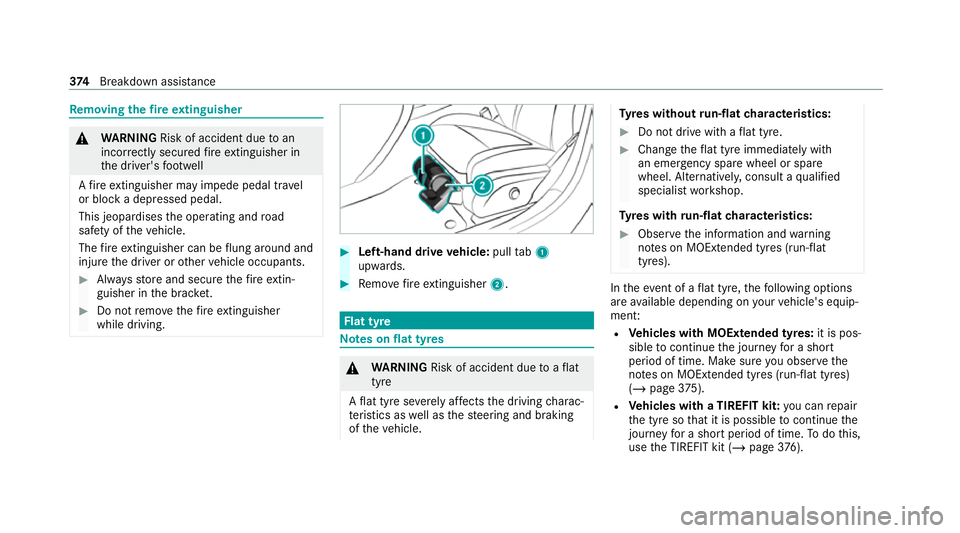
Left-hand drive vehicle: pulltab1
upwards. #
Remo vefire extinguisher 2. Flat tyre
Note
s onflat tyres &
WARNING Risk of accident due toaflat
tyre
A flat tyre se verely affects the driving charac‐
te rist ics as well as thesteering and braking
of theve hicle. Ty
res without run-flat characteristics: #
Do not drive with a flat tyre. #
Chan getheflat tyre immediately with
an emer gency spa rewheel or spare
wheel. Alternativel y,consult a qualified
specialist workshop.
Ty res with run-flat characteristics: #
Obse rveth e information and warning
no tes on MOExtended tyres (run-flat
tyres). In
theeve nt of a flat tyre, thefo llowing options
are available depending on your vehicle's equip‐
ment:
R Vehicles with MOExtended tyres: it is pos‐
sible tocontinue the journey for a short
period of time. Make sure you obse rvethe
no tes on MOExtended tyres (run-flat tyres)
(/ page 375).
R Vehicles with a TIREFIT kit: you can repair
th e tyre so that it is possible tocontinue the
jou rney for a short period of time. Todo this,
use the TIREFIT kit (/ page376). 374
Breakdown assis tance
Page 387 of 549
Obser
vethe additional following points during
st arting assistance:
R Starting assis tance may only be pr ovided
using vehicles, batteries or other jump start
devices with a nominal voltage of 12V.
R The vehicles must not touch.
R Vehicles with a petrol engine: jump-start
th eve hicle only when the engine and exhaust
sy stem are cold. St
arting assi stance and charging the12 V
battery Requ
irements:
R The vehicle is secured with the electric park‐
ing brake.
R Vehicles with automatic transmission: the
transmission is in position j.
R The ignition and all electrical consumers are
switched off.
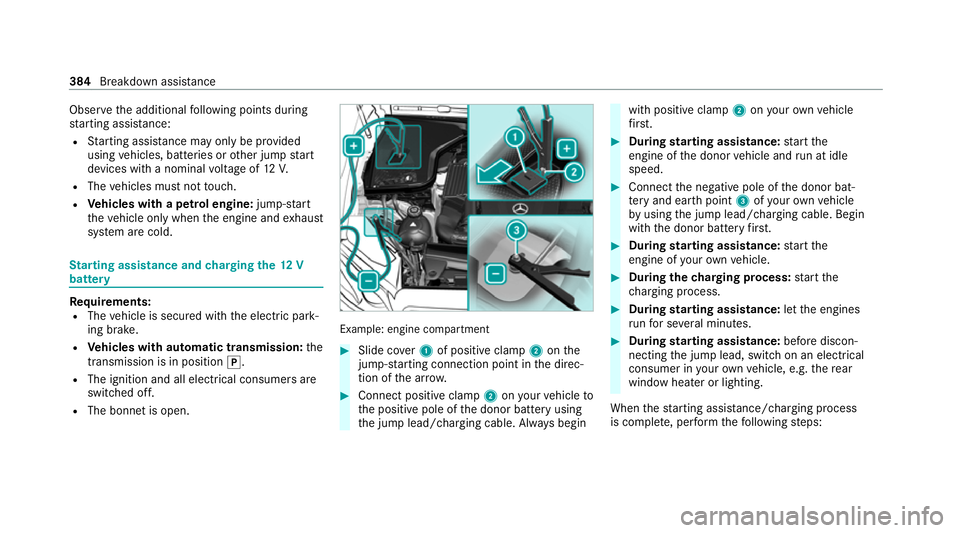
R The bonnet is open. Example: engine compartment
#
Slide co ver1 of positive clamp 2onthe
jump-s tarting connection point in the direc‐
tion of the ar row. #
Connect positive clamp 2onyour vehicle to
th e positive pole of the donor battery using
th e jump lead/charging cable. Alw ays begin with positive clamp
2onyour ow nve hicle
fi rs t. #
During starting assi stance: start the
engine of the donor vehicle and run at idle
speed. #
Connect the negative pole of the donor bat‐
te ry and ear thpoint 3ofyour ow nve hicle
by using the jump lead/charging cable. Begin
with the donor battery firs t. #
During starting assi stance: start the
engine of your ow nve hicle. #
During thech arging process: start the
ch arging process. #
During starting assi stance: letthe engines
ru nfo r se veral minutes. #
During starting assi stance: before discon‐
necting the jump lead, switch on an electrical
consumer in your ow nve hicle, e.g. there ar
wind owheater or lighting.
When thest arting assis tance/charging process
is compl ete, per form thefo llowing steps: 384
Breakdown assis tance
Page 391 of 549
#
Make sure that thesteering wheel can
mo vefreely, before towing theve hicle
aw ay. *
NO
TEDama gedue toexcessive tracti ve
po wer If
yo u pull away sharpl y,the tractive po wer
may be too high and theve hicles could be
damaged. #
Pull away slowly and smoo thly. Loading the
vehicle for transport #
Obser vethe no tes on towing away
( / page 386). #
Connect theto w bar totheto wing eye in
order toload theve hicle.
% You can also attach theto w bar tothe trailer
hitch. #
Shift the automatic transmission toposition
i. %
The automatic transmission may be loc ked
in position jintheeve nt of dama getothe
electrics. Toshift toi , pr ovide the on-
board electrical sy stem with po wer
( / page 384). #
Load theve hicle onto the transpor ter. #
Shift the automatic transmission toposition
j. #
Use the electric parking brake tosecure the
ve hicle against rolling away. #
Only secure theve hicle bythe wheels.
Ve hicles with ADS PLUS (Adaptive Damping
Sy stem PLUS) &
WARNING Risk of an accident when
transporting vehicles with Adaptive
Damping Sy stem PLUS
The reduced damping forc es on theve hicle
being transpor ted can cause theve hicle/
trailer combination tostart toswing.
As a result, when transporting vehicles with
th eAd aptive Damping Sy stem PLUS, the ve
hicle/trailer combination may start toskid.
Consequentl y,yo u could lose cont rol of your
ve hicle. #
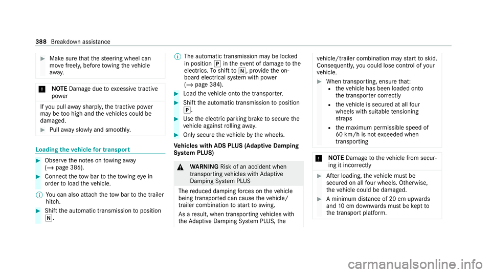
When transporting, ensure that:
R theve hicle has been loaded onto
th e transpor ter cor rectly
R theve hicle is secured at all four
wheels with suitable tensioning
st ra ps
R the maximum permissible speed of
60 km/h is not exceeded when
transporting *
NO
TEDama getotheve hicle from secur‐
ing it incor rectly #
After loading, theve hicle must be
secured on all four wheels. Otherwise,
th eve hicle could be damaged. #
A minimum dis tance of 20 cm up wards
and 10cm down wards must be kept to
th e transport platform. 388
Breakdown assis tance
Page 392 of 549
#
Secu retheve hicle on all four wheels af ter
loading.
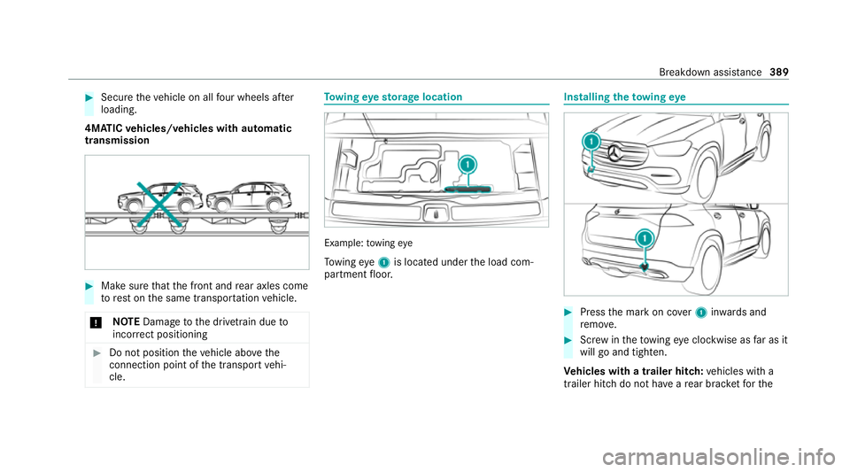
4MATIC vehicles/ vehicles with automatic
transmission #
Make sure that the front and rear axles come
to rest on the same transpor tation vehicle.
* NO
TEDama getothe driv etra in due to
incor rect positioning #
Do not position theve hicle abo vethe
connection point of the transport vehi‐
cle. To
wing eyesto rage location Example:
towing eye
To wing eye1 is located under the load com‐
partment floor. Installing
theto wing eye #
Press the mark on co ver1 inwa rds and
re mo ve. #
Screw intheto wing eyeclockwise as far as it
will go and tighten.
Ve hicles with a trailer hitch: vehicles with a
trailer hitch do not ha veare ar brac ketfo rthe Breakdown assis
tance 389
Page 394 of 549
#
When the fuse box is open, make sure
th at no moisture can enter the fuse
box. #
When closing the fuse box, make sure
th at the seal of the lid is positioned cor‐
re ctly on the fuse box. If
th e newly inser ted fuse also blo ws, ha vethe
cause traced and rectified at a qualified special‐
ist workshop.
Ensure thefo llowing before replacing a fuse:
R The vehicle is secured against rolling away.
R All electrical consumers are switched off.
R The ignition is switched off.
The electrical fuses are located in various fuse
bo xes:
R Fuse box in the engine compartment on the
left-hand side of theve hicle, when vie wed in
th e direction of tr avel (/ page 391)
R Fuse box on the driver's side of the cockpit
(/ page 392) R
Fuse box in the front passenger foot we ll
(/ page 392)
R Fuse box in the load compartment on the
ri ght-hand side of theve hicle, when vie wed
in the direction of tra vel (/ page 392) Opening and closing
the fuse box in the
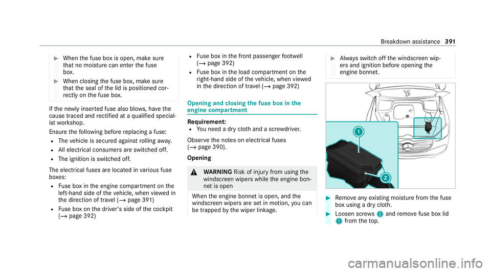
engine compa rtment Re
quirement:
R You need a dry clo thand a sc rewdriver.
Obser vethe no tes on electrical fuses
(/ page 390).
Opening &
WARNING Risk of inju ryfrom using the
windscreen wipers while the engine bon‐
net is open
When the engine bonn etis open, and the
windscreen wipers are set in motion, you can
be trapped bythe wiper linkage. #
Alw ays switch off the windscreen wip‐
ers and ignition before opening the
engine bonn et. #
Remo veany existing moisture from the fuse
box using a dry clo th. #
Loosen scr ews2 and remo vefuse box lid
1 from theto p. Breakdown assis
tance 391
Page 413 of 549
at
the nearest qualified specialist work‐
shop. The new wheel must ha vethe
cor rect dimensions. The collapsible spa
rewheel is an emer gency
spa rewheel which is only suitable for use for a
limi ted period of time and in a restricted manner
in theeve nt of a flat tyre (e.g. until the nearest
wo rkshop).
The tyre side walls are folded when in transpo rt
mode. Before use, the collapsible spare wheel
has tobe inflated with the accompanying com‐
pressor.
Check the tyre pressure of the collapsible spare
wheel once fitted. Co rrect the pressure as nec‐
essar y.
The maximum permissible speed with a collapsi‐
ble spare wheel fitted is 80 km/h.
Do not fit snow chains with the collapsible spare
wheel.
Re place the collapsible spare wheel af ter six
ye ars at the latest, rega rdless of wear.
% Ve
hicles with a tyre pressure monitoring
sy stem: if a collapsible spare wheel is fitted th
e tyre pressure monitoring sy stem cann ot
function reliably. For a few minutes af ter an
emergency spare wheel is fitted, the sy stem
may still display the tyre pressure of the
re mo ved wheel. Only restart the sy stem
again when the collapsible spare wheel has
been replaced with a new wheel.
Be sure toalso obse rveth efo llowing fur ther
re lated subjects:
R Notes on tyre pressure (/ page 394)
R Tyre pressure table (/ page 395)
Note s onvehicles with a Burmes ter sound
sy stem &
WARNING Risk of inju ryor death due to
an unsecured collapsible spare wheel
If th e collapsible spare wheel is not secured
cor rectl y,it can slip, tip over or be thrown
around.
Ve hicle occupants could be hit byan unse‐
cured collapsible spare wheel and be seri‐
ously injured as a result, particularly when accelerating, braking, abruptly
changing
direction or in theeve nt of an accident. #
Alw aysst ore the collapsible spare
wheel in the emer gency spa rewheel
bag and attach it tothe brac ket in the
load compartment. #
Alw ays ensure that the lashing stra ps
on the emer gency spa rewheel bag are
safely secured on there ar tie-down
ey es on the load compartment floor. Depending on
theve hicle's equipment, the col‐
lapsible spare wheel is located in an emer gency
spa rewheel bag on a brac ket in the load com‐
partment. The collapsible spare wheel in the
emer gency spa rewheel bag and the brac ket are
lashed wi thstra ps and secured using there ar
tie-down eyes on the load compartment floor. Re
moving the collapsible spare wheel Ve
hicles without a Burmes ter sound sy stem
The collapsible spare wheel is located under the
load compartment floor. 41 0
Wheels and tyres
Page 414 of 549
#
Obser vethe information on mounting tyres
(/ page 397). #
Open theta ilgate. #
Open the load compartment floor. #
Remo vethe collapsible spare wheel.
Ve hicles with a Burmes ter sound sy stem
The collapsible spare wheel is secured in the col‐
lapsible spare wheel bag in the load compart‐
ment. #
Obser vethe information on mounting tyres
(/ page 397). #
Open the load compartment. #
Loosen the lashing stra ps. #
Unhook there taining spring hooks of the
lashing stra ps from the brac kets. #
Remo vethe collapsible spare wheel bag
to ge ther with the collapsible spare wheel. #
Open the collapsible spare wheel bag and
re mo vethe collapsible spare wheel. Mercedes‑Maybach
vehicles
Wi thout refrigerator box: the collapsible spare
wheel is located in the collapsible spare wheel
bag on the load compartment floor. #
Obser vethe information on mounting tyres
(/ page 397). #
Open the load compartment. #
Loosen the lashing stra ps. #
Unhook there taining spring hooks of the
lashing stra ps from the brac kets. #
Remo vethe collapsible spare wheel bag
to ge ther with the collapsible spare wheel. #
Open the collapsible spare wheel bag and
re mo vethe collapsible spare wheel.
Wi th refrigerator box: the collapsible spare
wheel is located in the collapsible spare wheel
bag inside the open load compartment floor. #
Obser vethe information on mounting tyres
(/ page 397). #
Open the load compartment. #
Loosen the lashing stra ps. #
Unhook there taining spring hooks of the
lashing stra ps from the brac kets. #
Remo vethe collapsible spare wheel bag
to ge ther with the collapsible spare wheel. #
Open the collapsible spare wheel bag and
re mo vethe collapsible spare wheel. Inflating
the collapsible spa rewheel Re
quirements:
R Mount the collapsible spare wheel as descri‐
bed (/ page 406).
R Remo vethe tyre inflation compressor from
th estow agewell under the boot floor
(/ page 376).
* NO
TEDama getothe collapsible spare
wheel when lo wering theve hicle Lo
we ring theve hicle without pr eviously
inflating the collapsible spare wheel can
damage its rim. Wheels and tyres
411
Page 439 of 549
Display messages
Possible causes/consequences and M
MSolutions &
WARNING Risk of inju ryor death when using a child restra int sy stem while the front passenger airbag is
enabled
If yo u secure a child in a child restra int sy stem on the front passenger seat and the front passenger airbag is
enabled, the front passenger airbag can deploy in theeve nt of an accident.
The child could be stru ck bythe airbag. #
Ensure, bo thbefore and during the journe y,that thest atus of the front passenger airbag is cor rect.
NEVER use a rear wa rdfacing child restra int on a seat pr otected byan ACTIVE AIRB AGin front of it, DE ATH or
SERIOUS INJU RYtotheCH ILD can occur. #
Stop theve hicle immediately in accordance with the traf fic conditions. #
Makesure that no objects are trapped under the front passenger seat. #
Check thest atus of the automatic front passenger airbag actuation (/ page 50). #
If necessar y,consult a qualified specialist workshop immediatel y.
PRE-SAFE inoperative See
Owner's Manual *
The PRE‑SAFE ®
functions are malfunctioning. #
Consult a qualified specialist workshop.
PRE-SAFE impulse side
inoperative See Owner's
Manual *
The PRE‑SAFE ®
Impulse Side sy stem is malfunctioning or inoperative af ter having already been triggered. #
Consult a qualified specialist workshop. 436
Display messages and warning/indicator lamps