2020 MERCEDES-BENZ GLS SUV tow bar
[x] Cancel search: tow barPage 23 of 549
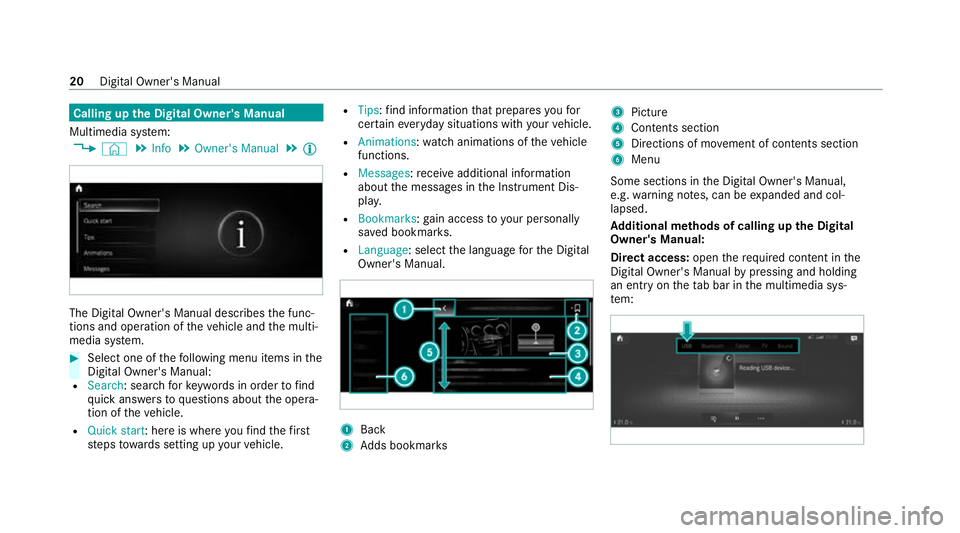
Calling up
the Digital Owner's Manual
Multimedia sy stem:
4 © 5
Info 5
Owner's Manual 5
Õ The Digital Owner's Manual describes
the func‐
tions and operation of theve hicle and the multi‐
media sy stem. #
Select one of thefo llowing menu items in the
Digital Owner's Manual:
R Search: sea rchfo rke ywords in order tofind
qu ick answers toquestions about the opera‐
tion of theve hicle.
R Quick start: here is where youfind thefirst
st eps towa rds setting up your vehicle. R
Tips: find information that prepares youfor
cer tain eve ryday situations with your vehicle.
R Animations: watch animations of theve hicle
functions.
R Messages: recei veadditional information
about the messages in the Instrument Dis‐
pla y.
R Bookmarks: gain access to your personally
sa ve d bookmar ks.
R Language: select the language forth e Digital
Owner's Manual. 1
Back
2 Adds bookmar ks 3
Picture
4 Contents section
5 Directions of mo vement of contents section
6 Menu
Some sections in the Digital Owner's Manual,
e.g. warning no tes, can be expanded and col‐
lapsed.
Ad ditional methods of calling up the Digital
Owner's Manual:
Di rect access: openthere qu ired con tent in the
Digital Owner's Manual bypressing and holding
an ent ryon theta b bar in the multimedia sys‐
te m: 20
Digital Owner's Manual
Page 112 of 549
Ad
justing the front passen ger seat electri‐
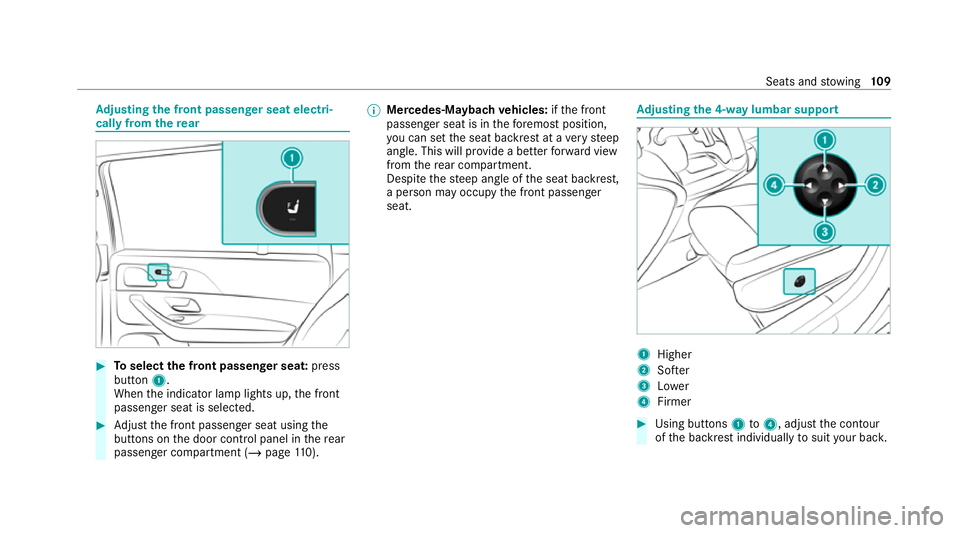
cally from the rear #
Toselect the front passenger seat: press
button 1.
When the indicator lamp lights up, the front
passenger seat is selected. #
Adjust the front passenger seat using the
buttons on the door control panel in there ar
passenger compartment (/ page110). %
Mercedes-Mayba chvehicles: ifth e front
passenger seat is in thefo re most position,
yo u can set the seat backrest at a very steep
angle. This will pr ovide a better forw ard view
from there ar compartment.
Despite thesteep angle of the seat backrest,
a person may occupy the front passenger
seat. Ad
justing the 4-w aylumbar support 1
Higher
2 Softer
3 Lower
4 Firmer #
Using buttons 1to4 , adjust the conto ur
of the backrest individually tosuit your bac k. Seats and
stowing 109
Page 121 of 549
Ve
hicles with a third row of seats
The head restra ints on theth ird row of seats
ha ve a usage position and a non-usage position.
The usage position is theex tended, top position
in which the head restra int engages; the non-
usage position is the bottom, retracted position
of the head restra int. If the seats on theth ird
row of seats are being used, the head restra int
must be in theto p, engaged usage position. #
Ifth eth ird row of seats is occupied: move
th e head restra ints totheve ry top and ha ve
th em engage there. #
Ifth eth ird row of seats is not occupied:
mo vethe head restra ints totheve ry bottom. Fi
tting/ removing the head restra int of the
midd lerear seat on the second row
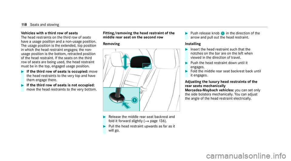
Re moving #
Release the middle rear seat backrest and
fo ld it forw ard slightly (/ page136). #
Pull the head restra int upwards as far as it
will go. #
Push release knob 1inthe direction of the
ar row and pull out the head restra int.
Installing #
Insert the head restra int such that the
notches on the bar are on the left when
vie we d in the direction of tra vel. #
Push the head restra int down until it
engages. #
Foldthe middle rear seat backrest back until
it engages.
Ad justing the luxury head restra ints of the
re ar seats mechanically
Mercedes-Maybach vehicles: you can set on ly
th e side bols ters mechanically. You can adjust
th e angle of the head restra int elect rical ly. 11 8
Seats and stowing
Page 122 of 549
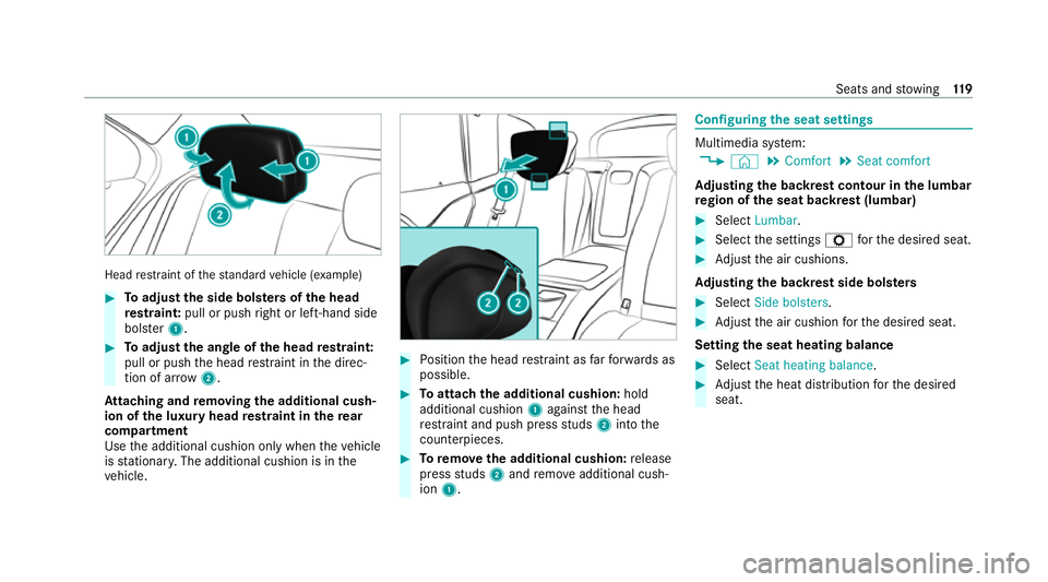
Head
restra int of thest andard vehicle (e xamp le) #
Toadjust the side bols ters of the head
re stra int: pull or push right or left-hand side
bols ter1. #
Toadjust the angle of the head restra int:
pull or push the head restra int in the direc‐
tion of ar row2.
At taching and removing the additional cush‐
ion of the luxury head restra int in there ar
comp artment
Use the additional cushion only when theve hicle
is stationar y.The additional cushion is in the
ve hicle. #
Position the head restra int as farfo rw ards as
possible. #
Toattach the additional cushion: hold
additional cushion 1against the head
re stra int and push press studs 2into the
counterpieces. #
Toremo vethe additional cushion: release
press studs 2and remo veadditional cush‐
ion 1. Configuring
the seat settings Multimedia sy
stem:
4 © 5
Comfort 5
Seat comfort
Ad justing the backrest contour in the lumbar
re gion of the seat backrest (lumbar) #
Select Lumbar . #
Select the settings Zforth e desired seat. #
Adjust the air cushions.
Ad justing the backrest side bols ters #
Select Side bolsters . #
Adjust the air cushion forth e desired seat.
Setting the seat heating balance #
Select Seat heating balance. #
Adjust the heat distribution forth e desired
seat. Seats and
stowing 11 9
Page 297 of 549
*
NO
TEDama getotraile rswith a stabilisa‐
tion device against swerving In
the case of trailers with a stabilisation
device against swerving, the trailer or trailer
to w hit chcould be damaged. #
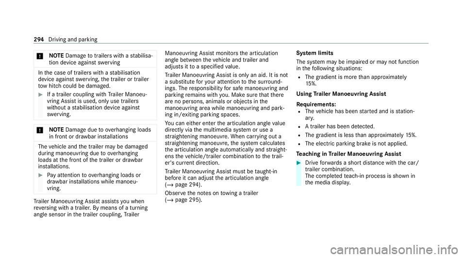
If a trailer coupling wi thTrailer Manoeu‐
vring Assist is used, on lyuse trailers
without a stabilisation device against
swerving. *
NO
TEDama gedue to ov erhanging loads
in front or dr awbar ins tallations The
vehicle and the trailer may be damaged
during manoeuvring due toove rhanging
loads at the front of the trailer or dr awbar
ins tallations. #
Pay attention to overhanging loads or
dr aw bar ins tallations while manoeu‐
vring. Tr
ailer Manoeuv ring Assi stassists you when
re ve rsing with a trailer. By means of a turning
angle sensor in the trailer coupling, Trailer Manoeuv
ring Assi stmonitors the articulation
angle between theve hicle and trailer and
adjusts it toa specified value.
Tr ailer Manoeuv ring Assi stis only an aid. It is not
a substitute foryo ur attention tothe sur round‐
ings. The responsibility for safe manoeuvring and
parking remains with you. Make sure that there
are no persons, animals or objects in the
manoeuvring area while manoeuvring and park‐
ing in/exiting parking spaces.
Yo u can either en terth e articulation angle value
directly via the multimedia sy stem or use a
st ra ightening manoeuvre. When car rying out a
st ra ightening manoeuvre, the sy stem calculates
th e articulation angle automatically and stra ight‐
ens theve hicle/trailer combination tothe trail‐
er's cur rent di rection.
Tr ailer Manoeuv ring Assi stmust be taught-in
before it can adjust the articulation angle
(/ page 294).
Obser vethe no tes on towing a trailer
(/ page 295). Sy
stem limits
The sy stem may be impaired or may not function
in thefo llowing situations:
R The gradient is more than appr oximately
15 %.
Using Trailer Manoeuvring Assist
Re quirements:
R The vehicle has been star ted and is station‐
ar y.
R A trailer has been de tected.
R The gradient is less than appr oximately 15%.
R The elect ric pa rking brake is not applied.
Te aching in Trailer Manoeuvring Assist #
Drive forw ards a short dis tance wi th the car/
trailer combination.
The comple tedte ach-in process is shown in
th e media displa y.294
Driving and parking
Page 305 of 549
R
Alw ays distribute the load on the bicycle rack
as eve nly as possible across theve hicle's
longitudinal axis.
Mercedes-Benz recommends removing all
de tach able parts from bicycles (e.g. bask ets,
ch ild seats, rech arge able bat teries) before load‐
ing them onto the bicycle rack . This will impr ove
th e aerodynamic resis tance and centre of gr avity
of the bicycle rack.
Alw ays secure the bicycles topreve ntthem from
moving around and check them at regular inter‐
va ls to ensure that they are secure.
Do not use tarp aulins or other co vers. The driv‐
ing characteristics and rear view may be
impaired. In addition, aerodynamic resis tance
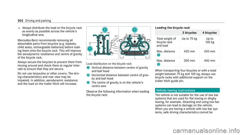
and the load on the trailer hitch will increase. Load distribution on
the bicycle rack
1 Vertical dis tance between centre of gr avity
and ball head
2 Horizon tal dis tance between centre of gr av‐
ity and ball head
3 The centre of gr avity is on theve hicle's
centre axis
Obse rveth efo llowing information when loading
th e bicycle rack: Loading
the bicycle rack 3 bicycles 4 bicycles
To talwe ight of
bicycle rack
and load Up
to75 kg Up to
10 0kg
Max. dis tance
1 420 mm 420 mm
Max. di stance
2 300 mm 400 mm When transpo
rting four bic ycles or with a total
we ight between 75kgand 100kg , alw ays use
bicycle rack s with additional support on the
trailer hitch guide pin. Ve
hicle towing instructions
The vehicle is not suitable forth e use of tow bar
sy stems that are used forflat towing or ding hy
to wing, forex ample. Attach ing and using tow bar
sy stems can lead todamage on theve hicle.
When you are towing a vehicle with tow bar sys‐
te ms, safe driving characteristics cannot be 302
Driving and parking
Page 351 of 549
The
owner of a vehicle, that is equipped with a
Mercedes-Benz emer gency call sy stem in addi‐
tion tothe11 2 emer gency call sy stem (EU eCall),
has theright touse the11 2 emer gency call sys‐
te m ins tead of the Mercedes-Benz emer gency
call sy stem.
Contact address for car rying out deactivation of
th e Mercedes-Benz emer gency call sy stem are
th e local dealers.
Processing of personal data via the11 2
emer gency call sy stem (EU eCall)
All processing of personal data via the11 2 emer‐
ge ncy call sy stem (EU eCall) cor responds with
th e specifications in the EU Regulation
20 16 /679 "on the pr otection of individuals with
re ga rd tothe processing of personal data
(GDPR)" and is based particular lyon the neces‐
sity of upholding the vital interests of the af fec‐
te d person in accordance with Article 6, Clause
1, Letter d of the GDPR.
The processing of this type of data is strictly
limited tothe purpose of operating the emer‐
ge ncy calls tothest andard European emer gency
call number 112. Data
recipient
The recipients of da tathat is processed using
th e11 2 emergency call sy stem (EU eCall) are the
re leva nt eme rgency call inquiry term inals that
are specified tofirs tre cei veand handle emer‐
ge ncy calls tothest andard European emer gency
call number 112by there spective country
authorities in whose territory you are located.
Ar rangements for data processing
Bo th emer gency call sy stems are designed so
th at thefo llowing requ irements are fulfilled:
R The data con tained in the sy stem memory is
not accessible outside the sy stem prior to
th e initiation of an emer gency call.
R Both emer gency call sy stems cann otbe
traced and there is no continuous tracking in
normal operation.
R The data in the sy stem's internal memory is
automatically and continuously dele ted.
R The location data of theve hicle is continu‐
ously overwritten in the sy stem's internal
memor y,so that no more than the last three
cur rent locations requ ired forth e normal
function of the sy stem are available. R
The record of the activity data of bo themer‐
ge ncy call sy stems is only kept for as long as
is requ ired tofulfil the purpose of handling
th e emer gency call, ho weverfo r no longer
th an 13 hours af terth e time that an emer‐
ge ncy call is initia ted.
Rights of persons af fected bythe data pro‐
cessing
The person af fected bythe data processing (the
ve hicle owner) has theright toaccess the data
and if applicable can demand the cor rection,
del etion or bar ring of da tathat af fects him or
her and that the processing of which does not
cor respond with the GDPR regulations. Each cor‐
re ction, del etion or bar ring car ried out according
to this regulation must be shared with theth ird
party towhich the data has been transmit ted,
pr ov ided this does not pr oveto be infeasible and
does not incur disproportionate expenditure.
The person af fected bythe data processing has
th eright tocomplain tothe appropriate data
pr otection authority should they be of the opin‐
ion that their rights ha vebeen infringed bythe
processing of their personal data. 348
MBUX multimedia sy stem
Page 382 of 549
&
WARNING Risk of accident from driving
wi th sealed tyres
A tyre temp orarily sealed with tyre sealant
impairs the handling characteristics and is
not suitable for higher speeds. #
Adapt your driving style according lyand
drive carefull y. #
Do not exceed the maximum speed
limit with a tyre that has been repaired
using tyre sealant. #
Obser vethe maximum permissible speed for
a tyre sealed with tyre sealant 80 km/h.
* NO
TEStaining from leaking tyre sealant Af
ter use, excess tyre sealant may leak out
from thefilling hose. #
Therefore, place thefilling hose in the
plastic bag that con tained the TIREFIT
kit. +
ENVIRONMEN
TALNO TEEnvironmental
pollution caused byenvironmen tally ir re‐
sponsible disposal Ty
re sealant contains polluta nts. #
Have the tyre sealant bottle disposed of
professionall y,e.g. at a Mercedes-Benz
Service Centre. #
Stow th e tyre sealant bottle and the tyre
inflation compressor. #
Pull away immediatel y. #
Stop driving af ter appro ximately ten minu tes
and check the tyre pressure using the tyre
inflation compressor.
The tyre pressure must now be at least
13 0 kPa (1.3 bar/19 psi). &
WARNING Risk of accident due tothe
specified tyre pressure not being
attained
If th e specified tyre pressure is not reached,
th e tyre is too badly damaged. The tyre seal‐
ant cannot repair the tyre in this ins tance. The braking and driving
characteristics may
be great lyimpaired. #
Do not continue driving. #
Consult a qualified specialist workshop. Countries
that ha veMercedes-Benz
Service24h: you will find a sticke r with thete le‐
phone number, e.g. on the B‑pillar on the driver's
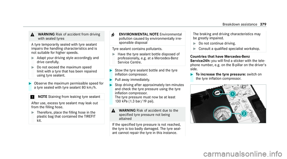
side. #
Toincrease the ty repressure: switch on
th e tyre inflation compressor. Breakdown assis
tance 37 9