2020 MERCEDES-BENZ CLS COUPE height
[x] Cancel search: heightPage 220 of 469
The
vehicle is lo wered again in thefo llowing sit‐
uations:
R When driving fasterthan 80 km/h.
R When driving between 60 km/h and
80 km/h for appro ximately thre e minutes.
R Afterch anging a drive program using the
DY NA MIC SELECT switch.
The vehicle is adjus tedto the height of the last
active drive program.
Lo weri ngtheve hicle #
Press button 1.
Indica tor lamp 2goes out. The vehicle is
adjus tedto the height of the active drive pro‐
gram.
Operation with a trailer or bicycle rack
If th e electrical connection has been cor rectly
es tablished tothe trailer or bicycle rack:
R Uptoappr oximately 30 km/h: the high le vel
can be selected rega rdless of the drive pro‐
gram. R
From appr ox. 30 km/h: theve hicle is adjus‐
te dto normal le vel,re ga rdless of drive pro‐
gram. Re
versing camera Fu
nction of there ve rsing camera
If yo u ha veactivated the function in the multime‐
dia sy stem (/ page 224), the image from the
re ve rsing camera is shown in the media display
when there ve rsege ar is engaged. Dynamic
guide lines show the path theve hicle will take
with the cur rent steering angle. This helps youto
orient yourself and toavo id obs tacles when
re ve rsing.
The reve rsing camera is only an aid. It is not a
substitute foryo ur attention tothe sur roundings.
The responsibility for safe manoeuvring and
parking remains with you. Make sure that there
are no persons, animals or objects etc., in the
manoeuvring area while manoeuvring and park‐
ing.
% You can open the co ver of there ve rsing
camera manually (/ page 224). The guide lines in
the media display show the
dis tances to yourvehicle. The dis tances dis‐
pl ay ed only apply toroad le vel.
Depending on theve hicle equipment, you can
select from thefo llowing vie ws:
R Normal view
R Wide-angle view
R Trailer view
The area behind theve hicle is displa yed as a
mir ror image, as in the inside rearview mir ror.
Ve hicles without Parking Assist PARKTRONIC
The following camera vie wsare available in the
multimedia sy stem: Driving and parking
217
Page 226 of 469
Sy
stem limits
The 360° Camera will not function or will only
partially function in thefo llowing situations:
R The doors are open.
R the outside mir rors are folded in.
R The boot lid is open.
R There is heavy rain, snow or fog.
R The light conditions are poor, e.g. at night.
R Cameras, or vehicle components in which
th e cameras are fitted, are dama ged, dirty or
co vered. Obser vethe information on vehicle
sensors and cameras (/ page179).
% Do not use the 360° Camera under such cir‐
cums tances. You could otherwise injure oth‐
ers or collide with objects when parking the
ve hicle.
Fo rte ch nical reasons, thest andard height of the
ve hicle may be altered if theve hicle is car rying a
heavy load and can result in inaccuracies in the
guide lines and in the display of thege nerated
ima ges. %
The contra stof the display may be impaired
by abrupt, direct sunlight or by other light
sources, e.g. when driving out of a garage . In
th is case, pay particular attention.
% Have the display repaired or replaced if, for
ex ample, pixel er rors considerably restrict its
use.
See the no tes on cleaning the 360° Camera
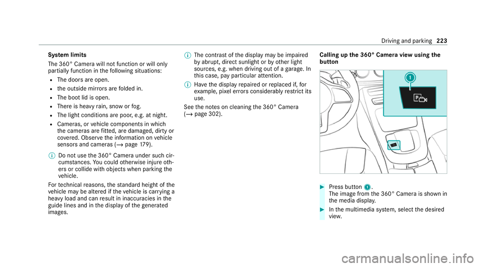
(/ page 302). Calling up
the 360° Camera view using the
button #
Press button 1.
The image from the 360° Camera is shown in
th e media displa y. #
Inthe multimedia sy stem, select the desired
vie w. Driving and pa
rking 223
Page 298 of 469
#
Neverto uch co mponents of the ignition
sy stem or the fuel injection sy stem
when the ignition is switched on. &
WARNING Risk of bu rns from hot com‐
ponent parts in the engine compartment
Cer tain component parts in the engine com‐
partment can be very hot, e.g. the engine,
th e cooler and parts of theex haust sy stem. #
Allow the engine tocool down and only
to uch co mponent parts described in
th efo llowing. &
WARNING Risk of inju ryfrom using the
windscreen wipers while the engine bon‐
net is open
When the engine bonn etis open, and the
windscreen wipers are set in motion, you can
be trapped bythe wiper linkage. #
Alw ays switch off the windscreen wip‐
ers and ignition before opening the
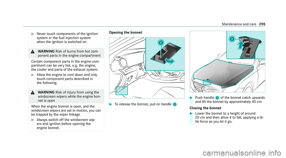
engine bonn et. Opening
the bonnet #
Torelease the bonn et, pull on handle 1. #
Push handle 1ofthe bonn etcatch up wards
and lift the bonn etby appr oximately 40 cm.
Closing the bonnet #
Lowe rth e bonn etto a height of around
20 cm and then allow it tofall, applying a lit‐
tle forc e as you let it go. Main
tenance and care 295
Page 359 of 469

#
Make sure that no windsc reen washer
concentrate spills out next tothefiller
opening. *
NO
TEDama getotheex terior lighting
due tounsuitable windsc reen washer
fl uid Uns
uitable windsc reen washer fluids may
damage the plastic sur face of theex terior
lighting. #
Only use windscreen washer fluids
which are also suitable for use on plas‐
tic sur faces, e.g. MB SummerFit or MB
Wi nterFit. *
NO
TEBlocked spr aynozzles caused by
mixing windscreen washer fluids #
Do not mix MB SummerFit and MB Win‐
te rFit with other windscreen washer flu‐
ids. Do not use distilled or de-ionised
water.Other‐
wise, thefill le vel sensor may be triggered er ro‐
neously.
Re commended windscreen washer fluid:
R abo vefreezing point: e.g. MB SummerFit
R below freezing point: e.g. MB WinterFit
Fo rth e cor rect mixing ratio, referto the informa‐
tion on the antif reeze contai ner.
Mix washer fluid with windsc reen washer fluid all
ye ar round. Ve
hicle data Ve
hicle dimensions The heights speci
fied may vary as a result of the
fo llowing factors:
R tyres
R load
R condition of the suspension
R optional equipment 356
Tech nical da ta
Page 360 of 469

Height when opened
Model
1 1Height
when
opened
CLS 300 d 4MATIC
CLS 350 4MATIC
CLS 400 d 4MATIC
CLS 450 4MATIC 18
93 mm
All other models 1887 mm Ve
hicle dimensions All models
Ve
hicle lengt h4 988 mm
Ve hicle width including out‐
side mir rors 2069 mm
Ve hicle width excluding out‐
side mir rors 18
90 mm
Wheelbase 2939 mm Ve
hicle height Model
Vehicle
height
CLS 300 d 4MATIC
CLS 350 4MATIC
CLS 400 d 4MATIC
CLS 450 4MATIC 14
35 mm
All other models 1429 mm We
ights and loads Please obser
vethefo llowing no tesfo rth e speci‐
fi ed vehicle data:
R Items of optional equipment increase the
unladen weight and reduce the pa yload.
R Vehicle-specific weight information can be
fo und on theve hicle identification plate
(/ page 345). Model
Maximumroof load
All models 75kg Tr
ailer hitch Gene
ral no tes on the trailer hit ch Modifications
tothe engine cooling sy stem may
be necessar y,depending on theve hicle model.
The retrofitting of a trailer hitch is only pe rmissi‐
ble if a towing capacity is specified in your vehi‐
cle documents.
Fu rther information can be obtained at a quali‐
fi ed specialist workshop. Te
ch nical da ta357
Page 457 of 469
Massage programme
overview .............. 99
Operating the memory function ..........1 06
Pa nel heating ....................................... 101
Re setting the settings .......................... 100
Setting options ...................................... 14
Wo rkout programme overview .............. .99
Seat belt ............................................... 38, 41
Ac tivating/deactivating seat belt
adjustment ............................................ 41
Ad justing the height .............................. 40
Care ....................................................3 04
Fa stening ............................................... 40
Pr otection ..............................................38
Re ar seat belt status display .................. 41
Re duced pr otection ...............................39
Re leasing .............................................. .41
Seat belt adjustment (function) ............. 41
Wa rning lamp ........................................ .41
Seat belt adjustment Activating/deactivating ......................... 41
Fu nction ................................................. 41
Seat belt tensioners
Ac tivation .............................................. 37Seat belt
warning
see Seat belt
Seat co ver (Care) ..................................... 304
Seat hea ter
Ac tivating/deactivating ...................... .100
Seat ventilation
Switching on/o ff................................. 101
Selecting a gear
see Changing gears
Selector le ver
see DIRECT SELECT le ver
Self-test Automatic front passenger front air‐
bag shutoff ............................................ 47
Sensors (care) ......................................... 302
Service see ASS YST PLUS
Service centre see Qualified specialist workshop
Service inter val display
see AS SYST PLUS Setting a speed
see Cruise control
Setting the map scale
see Map
Shift paddles see Steering wheel gearshift paddles
Shifting gears
Gea rshift recommendation .................. 16 4
Side airbag .................................................42
Side impact pr otection .......................... .226
Side windo ws............................................. 83
Au tomatic function ................................ 85
Child saf ety lock in there ar .................. .70
Closing .................................................. 83
Closing using theke y ............................ 85
Con venience closing ............................. 85
Co nvenience opening ............................85
Opening .................................................83
Opening with theke y ............................ .85
Problem .................................................86
Ra in-closing feature .............................. .85
Sliding sunroof Automatic features ................................ 88 454
Index
Page 462 of 469
Selection ............................................. 332
Snow chains ........................................ 327
St oring ................................................ 336
TIREFIT kit ............................................ 310
Ty re pressure (N otes) .......................... 328
Ty re pressure loss warning sy stem
(function) ............................................. 331
Ty re pressure monitoring sy stem
(function) ............................................. 330
Ty re pressure table .............................. 329
Un usual handling characteristics ........ .327 U
Un locking setting ...................................... 72
Up dates
Impor tant sy stem updates .................. 259
USB port Rear .................................................... .116 V
Ve hicle ...................................................... 14 9
Ac tivating/deactivating standby
mode .................................................. .178
Ad ditional door lock ...............................74 Collision de
tection (pa rking) ................ 17 7
Cor rect use ........................................... 30
Data acquisition ..................................... 31
Data storage .......................................... 31
Diagno stics connection ........................ .28
Equipment ............................................. 22
Implied warranty .................................... 31
Locking (auto matically) ......................... 77
Locking (from inside) ............................. 75
Locking (KEYLESS-GO) ..........................76
Locking/unlocking (emergency key) ...... 78
Lo we ring .............................................. 341
Medical aids .......................................... 30
Pa rking up .......................................... .178
QR code rescue card ............................. 31
Qualified specialist workshop ................29
Ra ising ................................................ 338
REA CHregulation ..................................30
Re gistration ...........................................30
St andby mode function ........................ 178
St arting (eme rgency operation
mode) .................................................. 14 9
St arting (Remo teOnline) ..................... 15 0
St arting (s tart/s top button) .................1 49
Switching off (s tart/s top button) .........1 72
To wing ................................................ .241 Un
locking (from inside) .......................... 75
Un locking (KEYLESS-GO) ...................... .76
Ve ntilating (co nvenience opening) ......... 85
Ve hicle data
Displ aying (DYNAMIC SELECT) ............ .161
Ro of load ............................................. 357
Ve hicle height ...................................... 356
Ve hicle length ...................................... 356
Ve hicle width ....................................... 356
Wheelbase ...........................................3 56
Ve hicle dimensions ................................. 356
Ve hicle identification number
see VIN
Ve hicle identification plate .................... 345
EU general operating pe rmit number .. 345
Maximum permissible gross vehicle
we ight ................................................ .345
Pa int code .......................................... .345
Pe rm issible axle load .......................... .345
VIN ...................................................... 345
Ve hicle interior
Cooling or heating (Remo teOnline) ..... 15 0
Ve hicle key
see Key Index
459