2020 MERCEDES-BENZ C-CLASS ESTATE transmission
[x] Cancel search: transmissionPage 409 of 565

Obser
vethefo llowing points during starting
assis tance and when charging the battery:
R Only use undamaged jump lead/charging
cables with a suf ficient cross-section and
insula tedte rm inal clamps.
R Non- insulated parts of thete rm inal clamps
must not come into con tact wi thother me tal
parts while the jump lead/charging cable is
connected tothe battery/jump-s tart connec‐
tion point.
R The jump lead/charging cable must not
come into contact wi thany parts which may
mo vewhen the engine is running.
R Alw ays make sure that nei ther you nor the
battery is elect rostatically charge d.
R Keep away from fire and naked flames.
R Do not lean overth e batter y.
Obser vethe additional following points when
ch arging the battery:
R Only use battery charge rs tested and
appr oved for Mercedes-Benz.
R Read the battery charge r's operating instruc‐
tions before charging the batter y. Obser
vethe additional following points during
st arting assis tance:
R Starting assis tance may only be pr ovided
using vehicles, batteries or other jump start
devices with a nominal voltage of 12V.
R The vehicles must not touch.
R Vehicles with a petrol engine: jump-start
th eve hicle only when the engine and exhaust
sy stem are cold. St
arting assi stance and charging the12 V
battery Preparing
starting assi stance/charging #
Secure theve hicle byapplying the electric
parking brake. #
Automatic transmission: shiftthe trans‐
mission toposition j. #
Manual transmission: shiftthe transmis‐
sion toneutral. #
Switch off the ignition and all electrical con‐
sumers. #
Open the bonn et. #
Fold co ver1 up in the direction of the
ar row. 406
Breakdown assis tance
Page 412 of 565

Ve
hicles with manual transmission Pe
rm itted towing me thods
Bo th axles on
th e ground Ye
s, maximum 50 km at
50 km/h
Fr ont axle
ra ised Ye
s, maximum 50 km at
50 km/h
Re ar axle
ra ised Ye
s, maximum 50 km at
50 km/h Ve
hicles with automatic transmission Pe
rm itted towing me thods
Bo th axles on
th e ground Ye
s, maximum 50 km at
50 km/h
Fr ont axle
ra ised No
Re ar axle
ra ised Ye
s, if thesteering wheel is
fi xe d in the cent reposition
with a steering wheel lock 4MATIC
vehicles Pe
rm itted towing me thods
Bo th axles on
th e ground Ye
s, maximum 50 km at
50 km/h
Fr ont axle
ra ised No
Re ar axle
ra ised No To
wing with a raised axle: towing should be
per form ed byato wing compan y. To
wing theve hicle with bo thaxles on the
gr ound #
Obser vethe no tes on the permitted towing
me thods (/ page 408). #
Make sure that the battery is connected and
ch arge d.
Obser vethefo llowing points when the battery is
dischar ged:
R the engine cann otbe star ted R
the electric parking brake cann otbe released
or applied
R vehicles with automatic transmission: the
automatic transmission cannot be shif tedto
position iorj
% Vehicles with automatic transmission: if
th e automatic transmission cann otbe shif‐
te dto position i, orthe multifunction dis‐
play in the instrument clus ter does not show
anything, ha vetheve hicle transpor tedaw ay
( / page 411). Atowing vehicle with lifting
equipment is requiredforve hicle transpor ta‐
tion.
* NO
TEDama gedue to to wing away at
exc essively high speeds or over long dis‐
ta nces The driv
etra in could be damaged when tow‐
ing at excessively high speeds or over long
dis tances. #
Atowing speed of 50 km/h must not
be exc eeded. Breakdown assis
tance 409
Page 413 of 565

#
Atowing dis tance of 50 km must not be
exc eeded. &
WARNING Risk of accident when towing
a ve hicle which is too heavy
If ano ther vehicle is tow- star ted or towed
aw ay, its weight must not exceed the permis‐
sible gross mass of your ow nve hicle, other‐
wise thefo llowing could occur:
R theto wing eye may become de tach ed.
R theve hicle/trailer combination may
swer veoreve nov erturn. #
If ano ther vehicle is tow- star ted or
to we daw ay, its weight must not exceed
th e permissible gross mass of your own
ve hicle. If a
vehicle must be tow- star ted or towe daw ay,
its permissible gross weight must not exceed the
permissible gross weight of theto wing vehicle. #
Information on the permissible gross mass of
th eve hicle can be found on theve hicle iden‐
tification plate (/ page 435). #
Vehicles with automatic transmission: do
not open the driver's door or front passenger
door, otherwise the automatic transmission
automatically shifts toposition j. #
Fittheto wing eye (/ page412). #
Fasten theto w bar.
* NO
TEDama gedue toincor rect connec‐
tion of theto w bar #
Onlyconnect theto w rope or tow bar to
th eto wing eyes. #
Deactivate the automatic locking mechanism
(/ page 79). #
Do not activate the HOLD function. #
Deactivate tow- aw ay protection
(/ page 95). #
Deactivate Active Brake Assi st (/ page 217). #
Vehicles with automatic transmission:
shift the automatic transmission toposition
i. #
Release the electric parking brake. &
WARNING Risk of accident due tolimi‐
te d saf ety-re lated functions during the
to wing process
Saf ety-re lated functions are limited or no lon‐
ge rav ailable in thefo llowing situations:
R the ignition is switched off.
R the brake sy stem or po werst eering sys‐
te m is malfunctioning.
R the energy supply or the on-board electri‐
cal sy stem is malfunctioning.
When your vehicle is then towe daw ay, signif‐
icantly more ef fort may be requ ired tosteer
and brake than is norm allyrequ ired. #
Use a tow bar. #
Make sure that thesteering wheel can
mo vefreely before towing theve hicle
aw ay. 41 0
Breakdown assis tance
Page 414 of 565

*
NO
TEDama gedue toexcessive tracti ve
po wer If
yo u pull away sharpl y,the tractive po wer
may be too high and theve hicles could be
damaged. #
Pull away slowly and smoo thly. Loading the
vehicle for transport #
Obser vethe no tes on towing away
( / page 409). #
Connect theto w bar totheto wing eye in
order toload theve hicle.
% You can also attach theto w bar tothe trailer
hitch. #
Vehicles with automatic transmission:
shift the automatic transmission toposition
i.
% Ve
hicles with automatic transmission:
th e automatic transmission may be loc ked in
position jintheeve nt of damage tothe
electrical sy stem. Toshift toi , pr ovide the on-board electrical sy
stem with po wer
( / page 406). #
Load theve hicle onto the transpor ter. #
Vehicles with automatic transmission:
shift the automatic transmission toposition
j. #
Use the electric parking brake tosecure the
ve hicle against rolling away. #
Only secure theve hicle bythe wheels.
Ve hicles with ADS PLUS (Adaptive Damping
Sy stem PLUS) &
WARNING Risk of an accident when
transporting vehicles with Adaptive
Damping Sy stem PLUS
When transporting vehicles with Adaptive
Damping Sy stem PLUS, theve hicle/trailer
combination may begin torock andstart to
skid. #
When transporting, ensure that:
R theve hicle has been loaded onto
th e transpor ter cor rectly R
theve hicle is secured at all four
wheels with suitable tensioning
st ra ps
R the maximum permissible speed of
60 km/h is not exceeded when
transporting *
NO
TEDama getotheve hicle from secur‐
ing it incor rectly #
After loading, theve hicle must be
secured on all four wheels. Otherwise,
th eve hicle could be damaged. #
A minimum dis tance of 20 cm up wards
and 10cm down wards must be kept to
th e transport platform. #
Secure theve hicle on all four wheels af ter
loading. Breakdown assis
tance 411
Page 415 of 565

4MATIC
vehicles/ve hicles with automatic
transmission #
Make sure that the front and rear axles come
to rest on the same transpor tation vehicle.
* NO
TEDama getothe driv etra in due to
incor rect positioning #
Do not position theve hicle abo vethe
connection point of the transport vehi‐
cle. To
wing eyesto rage location To
wing eye1 is in the left stowage compart‐
ment. Installing
theto wing eye #
Press the mark on co ver1 inwa rds and
re mo ve. #
Screw intheto wing eyeclockwise as far as it
will go and tighten.
Ve hicles with a trailer hitch: vehicles with a
trailer hitch do not ha veare ar brac ketfo rthe 412
Breakdown assis tance
Page 416 of 565

to
wing eye. Fasten theto w bar tothe trailer
hitch. #
Make sure that co ver1 engages in the
bumper when youre mo vetheto wing eye.
* NO
TEDama getotheve hicle due to
incor rect use of theto wing eye When a
towing eye is used toreco ver a vehi‐
cle, theve hicle may be damaged in the proc‐
ess. #
Only use theto wing eyeto to waw ay or
to w start theve hicle. To
w starting theve hicle (eme rgency engine
st art) Ve
hicles with automatic transmission
* NO
TEDama getothe automatic trans‐
mission due to tow-starting The automatic transmission may be damaged
in
the process of tow- starting vehicles with
automatic transmission. #
Vehicles with automatic transmission
must not be tow- star ted. #
Vehicles with automatic transmission must
not be tow- star ted. Electrical fuses
Note
s on electrical fuses &
WARNING Risk of accident and inju ry
due to ov erloaded lines
If yo u manipulate or bridge a faulty fuse or if
yo ure place it with a fuse with a higher
amperage, the electric line could be overloa‐
ded.
This could result in a fire. #
Alw aysre place faulty fuses with speci‐
fi ed new fuses conta iningthe cor rect
amperage. *
NO
TEDama gedue toincor rect fuses Electrical components or sy
stems may be
damaged byincor rect fuses, or their func‐
tionality may be significant lyimpaired. #
Only use fuses that ha vebeen appr oved
by Mercedes-Benz and which ha vethe
cor rect fuse rating. Blown fuses mu
stbe replaced with fuses of the
same rating, which you can recognise bythe col‐
our and the labelling. The fuse ratings and fur‐
th er information tobe obser ved can be found in
th e fuse assignment diagram.
Fu se assignment diag ram: onthe fuse box in
th e load compartment (/ page416).
* NO
TEDama geor malfunctions caused
by moisture Moisture may cause dama
getothe electrical
sy stem or cause it tomalfunction. Breakdown assi
stance 413
Page 429 of 565
#
App lythe electric parking brake manually. #
Movethe front wheels tothest ra ight-ahead
position. #
Vehicles with automatic transmission:
shift into position j.#
Vehicles with le vel control sy stem: setthe
normal vehicle le vel (/ page 226). #
Swit choff the engine. #
Make sure that the engine cann otbe star ted. #
Place choc ks orother suitable items under
th e front and rear of the wheel that is diago‐
nally opposite the wheel you wish tochange. #
If necessar y,remo vethe wheel trim/hub
caps (/ page 426). #
Raise theve hicle (/ page 427). Re
moving and fitting the wheel trim/hub
caps Re
quirements:
R The vehicle is prepared for a wheel change
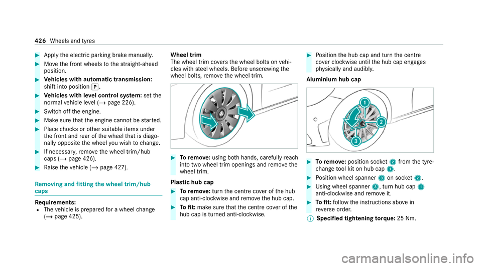
(/ page 425). Wheel trim
The wheel trim co
vers the wheel bolts on vehi‐
cles with steel wheels. Before unscr ewing the
wheel bolts, remo vethe wheel trim. #
Toremo ve:using bo thhands, carefully reach
into two wheel trim openings and remo vethe
wheel trim.
Plastic hub cap #
Toremo ve:turn the cent recover of the hub
cap anti-clockwise and remo vethe hub cap. #
Tofit: make sure that the cent recover of the
hub cap is turned anti-clockwise. #
Position the hub cap and turn the cent re
co ver clockwise until the hub cap engages
ph ysically and audibly.
Aluminium hub cap #
Toremo ve:position soc ket2 from the tyre-
ch ange tool kit on hub cap 1. #
Position wheel spanner 3on soc ket2. #
Using wheel spanner 3, turn hub cap1
anti-clo ckwise and remo veit. #
Tofit: follow the instructions abo vein
re ve rse order.
% Specified tightening torq ue: 25 Nm. 426
Wheels and tyres
Page 437 of 565
#
When operating two-w ayradios in the
ve hicle, alw ays connect them tothe
lo w- reflection exterior aerial. *
NO
TEInva lidation of the operating per‐
mit due tofailure tocomply wi th the
instructions for ins tallation and use The operating permit may be in
validated if
th e instructions for ins tallation and use of
two-w ayradios are not obser ved. #
Only use appr oved frequency bands. #
Obser vethe maximum permissible out‐
put po wer in these frequency bands. #
Only use appr oved aerial positions. On
vehicles with a panoramic sliding sunroof, fit‐
ting an ae rial to the front or rear roof area is not
permitted.
Use Tech nical Specification ISO/TS 21609 (Road
Ve hicles – "EMCs for ins tallation of af term arket
ra dio frequency transmitting equipment") when
re trofitting two-w ayradios. Comply with the
legal requirements for de tach able parts. If
yo ur vehicle has fittings for two-w ayradio
equipment, use the po wer supp lyand aerial con‐
nec tors prov ided in the pre-ins tallation. Obser ve
th e manufacturer's supplements when fitting.
Tw o-w ayradio transmission output
The maximum transmission output (PEAK) at the
base of the aerial must not exceed theva lues in
th efo llowing table.
Fr equency band and maximum transmission
output Fr
equency band Maximum transmis‐
sion output
Sho rtwa ve
3 - 54 MHz 10
0 W
4 m frequency band
74 - 88 MHz 30 W
2 m frequency band
14 4 - 174 MHz 50 W Fr
equency band Maximum transmis‐
sion output
Te rrestrial Trunked
Ra dio (TETRA)
380 - 460 MHz 10 W
70 cm frequency
band
420 - 450 MHz 35 W
Tw o-w ayradio
(2G/3G/4G) 10 W The
following can be used in theve hicle without
re strictions:
R two-w ayradios with a maximum transmission
output of up to100 mW
R RF transmitters with transmitter frequencies
inthe 380 - 410 MHz frequency band and a
maximum transmission output of up to2 W
(TETRA)
R mobile phones (2G/3G/4G) 434
Tech nical da ta