2020 MASERATI GRANTURISMO run flat
[x] Cancel search: run flatPage 50 of 286

force exerted on the shoulders while
the seat belt is in restraining mode.
Seat Belt Reminder System
(SBR)
The SBR system has the function to
remind the driver and the front
passenger to fasten the seat belts.
The function activates with engine
running. If the driver or front seat
passenger is unbelted, the seat belt
reminder light
and related message
will turn on in the instrument cluster
and remain on until both front seat
belts are fastened.
The warning sequence begins after the
vehicle speed is over 5 mph (8 km/h)
for more than 19 seconds, by blinking
the seat belt reminder light
and by
sounding an intermittent chime.
Once the sequence starts, it will
continue for the entire duration. Afterthe sequence completes, the seat belt
reminder light
remain illuminated
until the respective seat belts are
fastened.
If the opened door on the driver or
passenger side is closed and the
occupant presence sensor detects a
status change from occupant not
present to occupant present the
system will repeat the warning
sequence.
The driver should instruct all other
occupants to fasten their seat belts.
If a front seat belt is unbuckled while
traveling at speeds greater than 5 mph
(8 km/h), SBR system will provide both
audio and visual notification on the
instrument cluster.
The front passenger seat SBR is not
active when the front passenger seat is
not occupied. SBR may be triggered
when an animal or heavy object is on
the front passenger seat. It is
recommended to restrain pets in the
rear seat, in pet harnesses or pet
carriers that are secured by seat belts,
and properly stow cargo.
Maintaining the Seat Belts
• Always use the seat belts with the
belt completely flat, not twisted.
Make sure that the belt can move
freely without jamming.• The seat belts must be replaced
following every pretensioner
activation and whenever the belt
itself shows visible damages or
abrasions.
• Wash the seat belts by hand using
water and neutral soap, rinse them
and let them dry in the shade. Do
not use strong detergents, bleaches
or colorants and any other chemical
substance that may weaken the
fibers.
• Make sure the seat belt retractors do
not get wet: they will operate
properly only if they do not undergo
water infiltration.
Seat Belts and Pregnant
Women
Seat belts should also be worn by
pregnant women: the risk of injury in
the event of an accident is greatly
reduced for them and the unborn child
if they are wearing a seat belt. The
best way to protect the fetus is to
protect the mother.
Pregnant women must position the
lower part of the belt very low down
so that it passes over the pelvis and
under the abdomen (see figure).
Before Starting
2
46
Page 52 of 286
CAUTION!
• The Occupant Restraint Controller
(ORC) provides for the activation of
the pretensioners, front air bags or
side air bags, according to the type
of impact. Failure of one or more
systems to activate is not indicative
of a system malfunction.
• The front and/or side air bags may
inflate if the vehicle suffers a violent
impact involving the underbody
area, for example in case of violent
impacts against steps, sidewalks,
speed bumps, or when the vehicle
falls into potholes, or similar.
• The air bags release a small amount
of powder during deployment. This
powder is not harmful and does not
indicate the presence of a fire; in
addition, the surface of the deployed
air bag and the interior of the
vehicle may be covered with a
powdery residue: this powder may
irritate your skin and eyes. In case of
contact, wash the affected parts with
running water and neutral soap.
Front Air bags
WARNING!
The air bag is not a substitute for the
seat belts. Correct use of the seat
belts, in combination with the air bag,
will offer protection for the driver and
passenger in the front seat in the
event of a head-on collision.
The air bag system is composed of two
cushions that are designed to inflate
almost instantaneously. One is on the
driver’s side, in the center of the
steering wheel, and the other is on the
passenger side, inside the dashboard.
The front air bags of your vehicle have
been designed to inflate in two stages.
This allows the air bag to have
different rates of inflation based on
the crash severity, as assessed by the
air bag control unit.
Thedriver’s air bagis designed to be
deployed in certain head-on collisions
according to the following strategy.
• For low severity crashes, the air bag
control unit will not deploy the air
bag.
• For crashes of higher severity, the
control unit will deploy the driver air
bag in low energy mode.• For crashes of even higher severity,
the control unit will deploy the
driver air bag in high energy mode.
Thefront passenger’s air bagis
designed to be deployed in certain
head-on collisions according to the
following strategy.
• For low severity crashes, the air bag
control unit will not deploy the air
bags.
• For crashes of higher severity, the
control unit will deploy the air bag in
low energy mode.
• For crashes of even higher severity,
the control unit will deploy the air
bag in high energy mode.
WARNING!
•Never place an object over or near
the driver and passenger air bags. In
the event that the passenger air bag
is deployed, it will project any object
over it, or near it, in the passenger
compartment at very high speed.
The object will be transformed into a
projectile propelled in the passenger
compartment. This could cause
serious injuries.
•Do not tamper or damage the air
bag modules. If, for any reason, an
Before Starting
2
48
Page 71 of 286

•Never place or install floor mats or
other floor coverings in the vehicle
that cannot be properly secured to
prevent them from moving and
interfering with the pedals.
•Never put floor mats or other floor
coverings on top of already installed
floor mats. Additional floor mats
and other coverings will reduce the
size of the pedal area and interfere
with the pedals.
•Check mounting of mats on a
regular basis. Always properly
reinstall and secure floor mats that
have been removed for cleaning.
•Always make sure that objects
cannot fall into the driver footwell
while the vehicle is moving. Objects
can become trapped under the
brake pedal and accelerator pedal
causing a loss of vehicle control.
•Mounting posts must be properly
installed, if not equipped from the
factory. Failure to properly follow
floor mat installation or mounting
can cause interference with the
brake pedal and accelerator pedal
operation causing loss of control of
the vehicle.Tires
• Examine tires for excessive tread
wear and uneven wear patterns.
• Check for stones, nails, glass, or
other objects lodged in the tread or
sidewall.
• Inspect the tread for cuts and cracks.
• Inspect sidewalls for cuts, cracks and
bulges.
• Check the wheel nuts for tightness.
• Check the tires (see “Tire Inflation
Pressure” chapter in section
“Features and Specifications”) for
proper cold inflation pressure.
Lights and Indicator Lights
• Have someone observe the
operation of exterior lights while
you operate the controls (see
“Lights” chapter in section
“Understanding the Vehicle”).
• Check turn signal and high beam
indicator lights on the instrument
cluster (see “Instrument Cluster”
chapter in section “Dashboard
Instruments and Controls”).
Door Latches
• Check for positive closing, latching,
and locking of doors and trunk lid
(see chapter “Doors” and “Open and
Close the Trunk Lid” in this section).Fluid Leaks
• Check area under vehicle after
overnight parking for recent fluid
leaks (oil, fuel, etc.).
• If gasoline fumes are detected or
fluid leaks are suspected, contact an
Authorized Maserati Dealer.
WARNING!
California Proposition 65
Operating, servicing and maintaining
a passenger vehicle or off-road vehicle
can expose you to chemicals including
such as, engine exhaust, carbon
monoxide, phthalates and lead, that
which are know to the State of
California to cause cancer and birth
defects or other reproductive harm. To
minimize exposure, avoid breathing
exhaust, do not idle the engine except
as necessary, service your vehicle in a
well-ventilated area and wear gloves
or wash your hands frequently when
servicing your vehicle. For more
information go to:
www.P65Warnings.ca.gov/passenger-
vehicle
Before Starting
2
67
Page 192 of 286
• after inverting the wheels;
• if you are not sure whether at least
one of the operations above was
performed.
If you simply corrected the tire
inflation pressure, you do not need to
recalibrate the system.
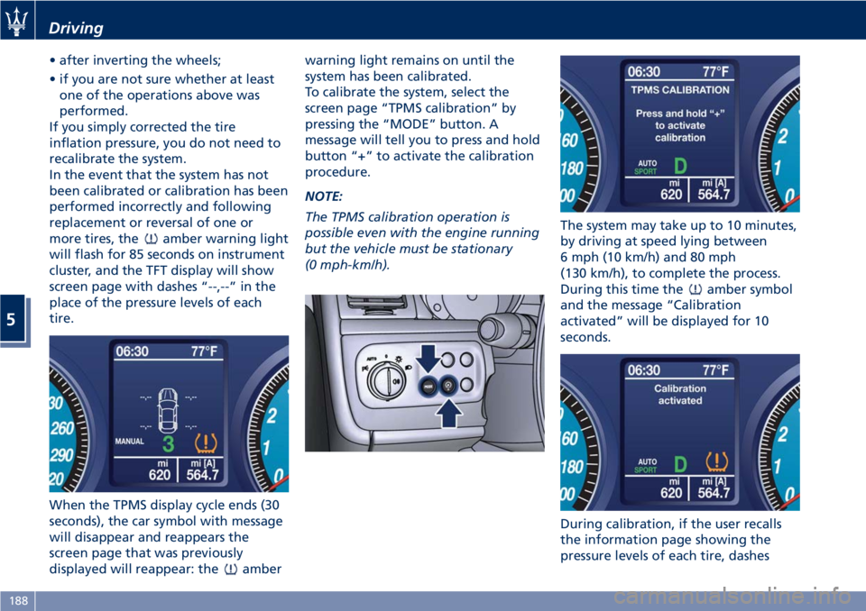
In the event that the system has not
been calibrated or calibration has been
performed incorrectly and following
replacement or reversal of one or
more tires, the
amber warning light
will flash for 85 seconds on instrument
cluster, and the TFT display will show
screen page with dashes “--,--” in the
place of the pressure levels of each
tire.
When the TPMS display cycle ends (30
seconds), the car symbol with message
will disappear and reappears the
screen page that was previously
displayed will reappear: the
amberwarning light remains on until the
system has been calibrated.
To calibrate the system, select the
screen page “TPMS calibration” by
pressing the “MODE” button. A
message will tell you to press and hold
button “+” to activate the calibration
procedure.
NOTE:
The TPMS calibration operation is
possible even with the engine running
but the vehicle must be stationary
(0 mph-km/h).The system may take up to 10 minutes,
by driving at speed lying between
6 mph (10 km/h) and 80 mph
(130 km/h), to complete the process.
During this time the
amber symbol
and the message “Calibration
activated” will be displayed for 10
seconds.
During calibration, if the user recalls
the information page showing the
pressure levels of each tire, dashes
Driving
5
188
Page 206 of 286
Tool Kit
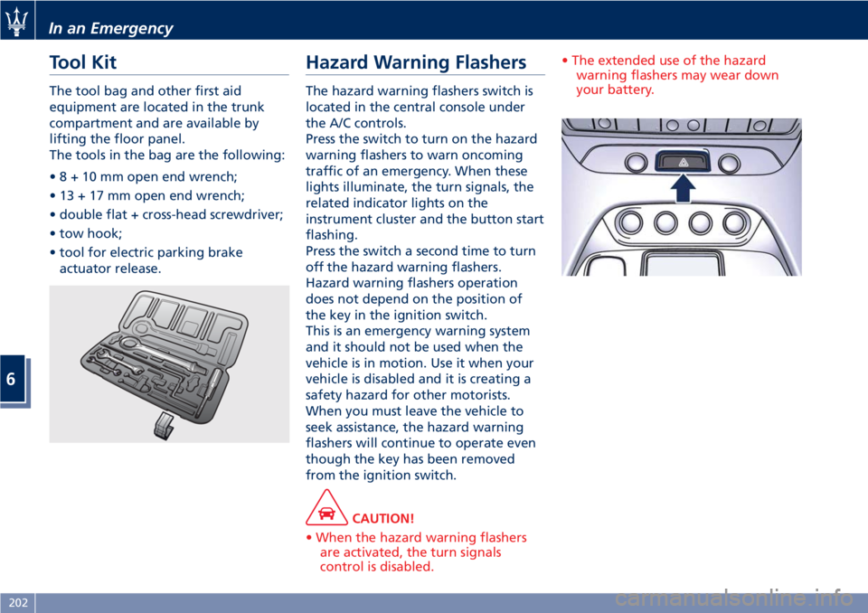
The tool bag and other first aid
equipment are located in the trunk
compartment and are available by
lifting the floor panel.
The tools in the bag are the following:
•8+10mmopen end wrench;
• 13 + 17 mm open end wrench;
• double flat + cross-head screwdriver;
• tow hook;
• tool for electric parking brake
actuator release.
Hazard Warning Flashers
The hazard warning flashers switch is
located in the central console under
the A/C controls.
Press the switch to turn on the hazard
warning flashers to warn oncoming
traffic of an emergency. When these
lights illuminate, the turn signals, the
related indicator lights on the
instrument cluster and the button start
flashing.
Press the switch a second time to turn
off the hazard warning flashers.
Hazard warning flashers operation
does not depend on the position of
the key in the ignition switch.
This is an emergency warning system
and it should not be used when the
vehicle is in motion. Use it when your
vehicle is disabled and it is creating a
safety hazard for other motorists.
When you must leave the vehicle to
seek assistance, the hazard warning
flashers will continue to operate even
though the key has been removed
from the ignition switch.
CAUTION!
• When the hazard warning flashers
are activated, the turn signals
control is disabled.• The extended use of the hazard
warning flashers may wear down
your battery.
In an Emergency
6
202
Page 209 of 286
Operating, servicing and maintaining
a passenger vehicle or off-road vehicle
can expose you to chemicals including
such as, engine exhaust, carbon
monoxide, phthalates and lead, that
which are know to the State of
California to cause cancer and birth
defects or other reproductive harm. To
minimize exposure, avoid breathing
exhaust, do not idle the engine except
as necessary, service your vehicle in a
well-ventilated area and wear gloves
or wash your hands frequently when
servicing your vehicle.
NOTE:
For the tire repair procedures with tire
repair kit see instructions included in
the kit.
This kit will provide a temporary tire
seal, allowing you to drive your
vehicle up to 6 miles (10 km) with a
maximum speed of 50 mph (80 km/h).
CAUTION!
• Intruding objects (e.g., screws or
nails) should not be removed from
the tire, which could compromise
the repair with the tire repair kit.
• Do not use the tire repair kit if the
tire shows lateral damages and/orthe rim is damaged by driving with
flat tire.
• Tire repair kit can be used in outside
temperatures down to
approximately -4°F (-20°C).
• Replace the tire repair kit sealant gas
cylinder prior to the expiration date
(printed on the gas cylinder label) to
assure optimum operation of the
system.
NOTE:
•The compressor power plug can be
inserted either in the 12 V power
outlet housed in the trunk or inside
the passenger compartment (see
“Interior Features” in section
“Understanding the Vehicle”).
•When having the tire serviced,
advise theAuthorized Maserati
Dealeror service center that the tire
has been sealed using the tire repair
kit.
Using the Compact Spare
Wheel (for versions/markets
where provided)
Upon request, the vehicle may come
equipped with a compact spare wheel
(emergency wheel), jack and tools for
replacing a wheel.The compact spare wheel is stored in
the trunk and is supplied deflated in
order to limit the amount of space
occupied. An electric compressor is
also provided for inflating. In the
event of a tire puncture, proceed as
follows.
• Stop the vehicle in a place that does
not constitute a danger to traffic
and where the wheel can be
changed safely. The vehicle must be
level and on firm ground.
• Select the P (Park) mode and then
engage manually the electric
parking brake and turn the key in
the ignition switch toSTOP (OFF)
position.
• If necessary, turn the hazard warning
flashers on and place the warning
triangle at the required distance.
WARNING!
•The jack should be used on level
firm ground wherever possible.
•It is recommended that the wheels
of the vehicle be chocked, and that
no person should remain in a vehicle
that is being jacked.
•If the vehicle has been stopped on a
(Continued)
In an Emergency
6
205
Page 210 of 286
(Continued)
slope or an uneven surface, place
chocks or other suitable items in
front of or behind the wheels to
stop the vehicle from moving.
•Never start or run the engine with
the vehicle on a jack.
•No person should place any portion
of their body under a vehicle that is
supported by a jack.
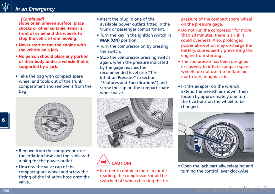
• Take the bag with compact spare
wheel and tools out of the trunk
compartment and remove it from the
bag.
• Remove from the compressor case
the inflation hose and the cable with
a plug for the power outlet.
• Unscrew the valve cap of the
compact spare wheel and screw the
fitting of the inflation hose onto the
valve.• Insert the plug in one of the
available power outlets fitted in the
trunk or passenger compartment.
• Turn the key in the ignition switch in
MAR (ON)position.
• Turn the compressor on by pressing
the switch.
• Stop the compressor pressing switch
again, when the pressure indicated
by the gage reaches the
recommended level (see “Tire
Inflation Pressure” in section
“Features and Specifications”) and
screw the cap on the compact spare
wheel valve.
CAUTION!
• In order to obtain a more accurate
reading, the compressor should be
switched off when checking the tirepressure of the compact spare wheel
on the pressure gage.
• Do not run the compressor for more
than 20 minutes: there is a risk it
could overheat. Also, prolonged
power absorption may discharge the
battery, subsequently preventing the
engine from starting.
• The compressor has been designed
exclusively to inflate compact spare
wheels; do not use it to inflate air
mattresses, dinghies etc.
• Fit the adapter on the wrench.
Extend the wrench as shown, then
loosen by approximately one turn,
the five bolts on the wheel to be
changed.
• Open the jack partially, releasing and
turning the control lever clockwise.
In an Emergency
6
206
Page 213 of 286
7 lbf·ft / 98 ± 10 Nm). This is
equivalent to a load of
approximately 44 lb (20 kg) being
placed on the handle of the wrench
supplied when extended for use.
•After refitting the standard wheel,
check the tire pressure.
Once finished:
• completely deflate the compact
spare wheel by pressing on the valve
with the overhang of the valve cap;
• wrap the power cable and the
inflation hose inside the compressor
case;
• place the compressor, the jack, the
wrench and the adapter in the
container inside the compact spare
wheel;
• put the compact spare wheel in its
bag and put it back in the trunk
compartment.
Emergency Release of the
Parking Brake
In the event the electric parking brake
locks due to a total system failure (see
“Parking Brake” in section “Driving”),
it is not possible to move the vehicle,
since the thrust action of the brake
shoes will lock the rear wheels.
For moving the vehicle it is therefore
necessary to manually act on the
electric actuator to release the
pressure of the brake shoes on the
rear wheels by performing the
following operation.
CAUTION!
If the parking brake has been
activated in manual or automatic
mode and it is not possible to release
it by operating on the lever of the
central console, do not move the
vehicle since rear brake calipers might
be damaged. If you are not able to
perform the following operation, to
move the vehicle, load it on a rescue
vehicle, avoiding to move it. For more
information on vehicle towing, see
"Towing a Disabled Vehicle" chapter
in this section.
Manual Release Procedure
To manually release the parking brake,
you need to use the special tool
provided in the tool kit (see "Tool Kit"
in this section).
Proceed as follows:
• remove any luggage and/or the bag
containing the compact spare wheel
(if equipped) from the trunk
compartment;
• remove the floor panel from the
trunk compartment;
• remove the inside covering panel
from the battery compartment;
• remove the container in the rear
part of the trunk compartment
unscrewing its fastenings;
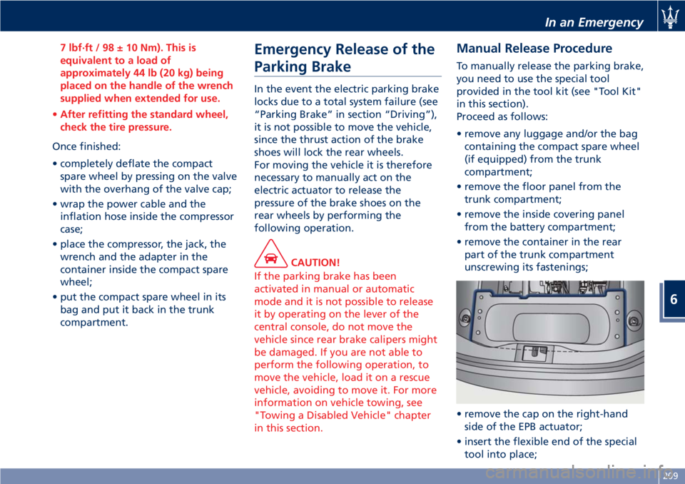
• remove the cap on the right-hand
side of the EPB actuator;
• insert the flexible end of the special
tool into place;
In an Emergency
6
209