Page 246 of 286
• Undo the four retaining screws and
remove the cover.
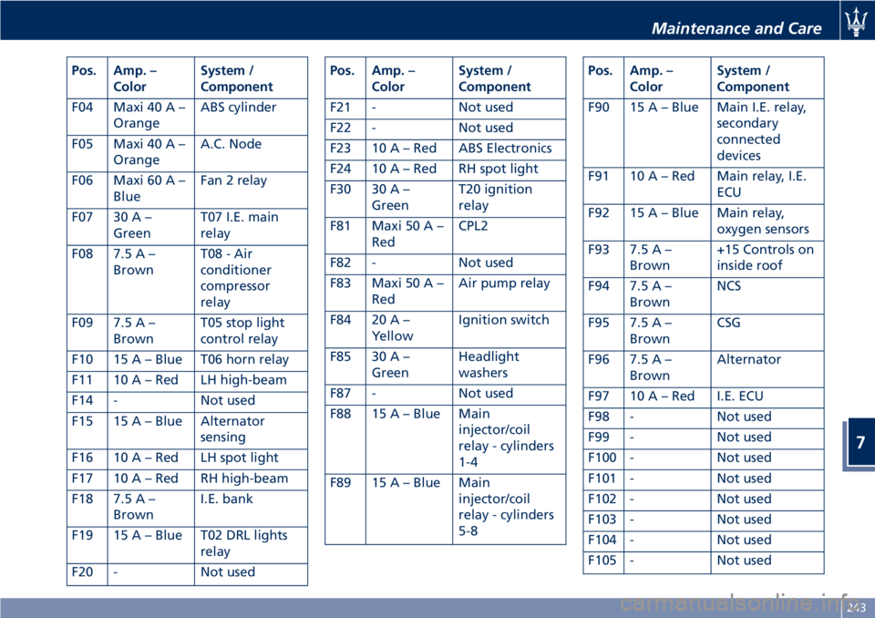
The fuses are housed in three control
boxes.The following table points out the
position as featured in the picture, the
type and function of the fuses
included in these control boxes.
CAUTION!
If you need to wash the engine
compartment, do not direct the jet of
water for too long directly on the
engine compartment ECU.
Engine Compartment Fuses
Pos. Amp. –
ColorSystem /
Component
F01 Maxi 60 A –
BlueFan 1 relay
F02 Maxi 30 A –
GreenABS valves
F03 Maxi 20 A –
YellowT03 spot lights
relay
Maintenance and Care
7
242
Page 247 of 286

Pos. Amp. –
ColorSystem /
Component
F04 Maxi 40 A –
OrangeABS cylinder
F05 Maxi 40 A –
OrangeA.C. Node
F06 Maxi 60 A –
BlueFan 2 relay
F07 30 A –
GreenT07 I.E. main
relay
F08 7.5 A –
BrownT08 - Air
conditioner
compressor
relay
F09 7.5 A –
BrownT05 stop light
control relay
F10 15 A – Blue T06 horn relay
F11 10 A – Red LH high-beam
F14 - Not used
F15 15 A – Blue Alternator
sensing
F16 10 A – Red LH spot light
F17 10 A – Red RH high-beam
F18 7.5 A –
BrownI.E. bank
F19 15 A – Blue T02 DRL lights
relay
F20 - Not usedPos. Amp. –
ColorSystem /
Component
F21 - Not used
F22 - Not used
F23 10 A – Red ABS Electronics
F24 10 A – Red RH spot light
F30 30 A –
GreenT20 ignition
relay
F81 Maxi 50 A –
RedCPL2
F82 - Not used
F83 Maxi 50 A –
RedAir pump relay
F84 20 A –
YellowIgnition switch
F85 30 A –
GreenHeadlight
washers
F87 - Not used
F88 15 A – Blue Main
injector/coil
relay - cylinders
1-4
F89 15 A – Blue Main
injector/coil
relay - cylinders
5-8Pos. Amp. –
ColorSystem /
Component
F90 15 A – Blue Main I.E. relay,
secondary
connected
devices
F91 10 A – Red Main relay, I.E.
ECU
F92 15 A – Blue Main relay,
oxygen sensors
F93 7.5 A –
Brown+15 Controls on
inside roof
F94 7.5 A –
BrownNCS
F95 7.5 A –
BrownCSG
F96 7.5 A –
BrownAlternator
F97 10 A – Red I.E. ECU
F98 - Not used
F99 - Not used
F100 - Not used
F101 - Not used
F102 - Not used
F103 - Not used
F104 - Not used
F105 - Not used
Maintenance and Care
7
243
Page 248 of 286
Pos. Amp. –
ColorSystem /
Component
F106 - Not used
F107 - Not used
Fuses in Passenger
Compartment
• To access the fuses lift the guard on
the left side of the steering wheel.
The fuses are housed in two control
boxes.The following table points out the
position as featured in the picture, the
type and function of the fuses
included in these control boxes.
Maintenance and Care
7
244
Page 249 of 286

Passenger Compartment Fuses
Pos. Amp. –
ColorSystem / Component
F12 15 A –
BlueRight-hand low
beam
F13 15 A –
BlueLeft-hand low beam
F31 7.5 A –
BrownA/C unit, NBC (Body
Computer Node),
high beam relay
F32 10 A –
RedDomelights, step
lights, CAV, driver-
and passenger-side
footwell lights,
outside mirror lights
F33 30 A –
GreenDriver’s seat
(movement)
F34 30 A –
GreenPassenger’s seat
(movement)
F35 7.5 A –
BrownACC, FN and LF relay
coil
F36 10 A –
RedNQS
F37 10 A –
RedNQS (Instrument
Cluster Node), CPP,
CPD
F38 15 A –
BlueRear lid lock
Pos. Amp. –
ColorSystem / Component
F39 15 A –
BlueNIM (Inside Roof
Node), NCL (Air
conditioning and
heating system
node), OBD socket,
CSA (Alarm system
siren ECU), CAV
(Motion sensing
alarm ECU), radio,
NAVTRAK
F40 30 A –
GreenHeated rear window
F41 - Not used
F42 7.5 A –
BrownPower supply for
control panel on roof
F43 30 A –
GreenWindshield
wiper/washer
(Connected Devices
Relay INT/A)
F44 20 A –
YellowFront and rear power
outlets (INT/A device
relay) front seat
heating (passenger
side)
F45 - Not used
F46 20 A –
YellowNPG/NPP locksPos. Amp. –
ColorSystem / Component
F47 30 A –
GreenNPG (Driver’s door
node)
F48 30 A –
GreenNPP (Passenger’s
door node)
F49 7.5 A –
BrownNVO (Steering wheel
node), CSG (Power
steering ECU), CSP
(Twilight/rain sensor
ECU), NIM (Inside
Roof Node), NCL,
Radio, CEM, CRP,
domelight molding,
windshield wiper
controls, NAVTRAK
F50 7.5 A –
BrownAir bag system
F51 7.5 A –
BrownNCA (Automatic
Gearbox Node)
F52 15 A –
BlueFront seat heating
(driver side) (INT/A
device relay)
F53 10 A –
RedRear fog lights
Maintenance and Care
7
245
Page 250 of 286
Fuses in Trunk Compartment
• To access the fuses, remove the floor
panel.
• Remove the inside covering panel of
the battery compartment.
There are two control boxes.
• To access the fuses inside the control
boxes, remove the covers by levering
up the fastening tabs.The following table points out the
position as featured in the picture, the
type and function of the fuses
included in these control boxes.Trunk Compartment FusesPos. Amp. –
ColorSystem / Component
F25 - Not used
F26 - Not used
F27 - Not used
F28 - Not used
F29 - Not used
F53 - Not used
F54 30 A –
GreenHI-Fi amplifier
F55 - Not used
F56 10 A –
Red+30 NAG, NTV,
Harman tuner, MTC+
(Japan)
F57 - Not used
F58 7.5 A –
BrownRH Reverse from T23
F59 - Not used
F60 7.5 A –
BrownNSP
F61 7.5 A –
BrownT24 third stop
F62 20 A –
YellowNCA
F63 15 A –
BlueFuel flap T25 relay,
+30 Battery charge
Maintenance and Care
7
246
Page 251 of 286

Pos. Amp. –
ColorSystem / Component
F64 - Not used
F65 10 A –
RedKey-Lock solenoid
F66 20 A –
YellowFuel pumps
F67 - Not used
F68 - Not used
F69 - Not used
F77 - Not used
F78 20 A –
YellowPower outlet
F79 - Not used
F80 25 A –
WhiteBass boxBulb Replacement
The signal failure of an external light
(turn signal, low beam and high beam,
license plate light, reverse light, brake
light and rear fog light) is
communicated to the instrument
cluster that displays on the TFT screen
the
oramber warning light
and a text message indicating which
light is faulty.
Front Headlights
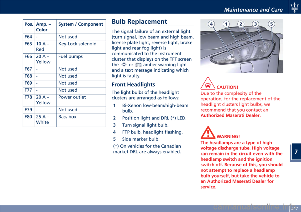
The light bulbs of the headlight
clusters are arranged as follows:
1Bi-Xenon low-beam/high-beam
bulb.
2Position light and DRL (*) LED.
3Turn signal light bulb.
4FTP bulb, headlight flashing.
5Side marker bulb.
(*) On vehicles for the Canadian
market DRL are always enabled.
CAUTION!
Due to the complexity of the
operation, for the replacement of the
headlight clusters light bulbs, we
recommend that you contact an
Authorized Maserati Dealer.
WARNING!
The headlamps are a type of high
voltage discharge tube. High voltage
can remain in the circuit even with the
headlamp switch and the ignition
switch off. Because of this, you should
not attempt to replace a headlamp
bulb yourself, but take the vehicle to
an Authorized Maserati Dealer for
service.
Maintenance and Care
7
247
Page 252 of 286

Tail-Light Clusters Light Bulbs
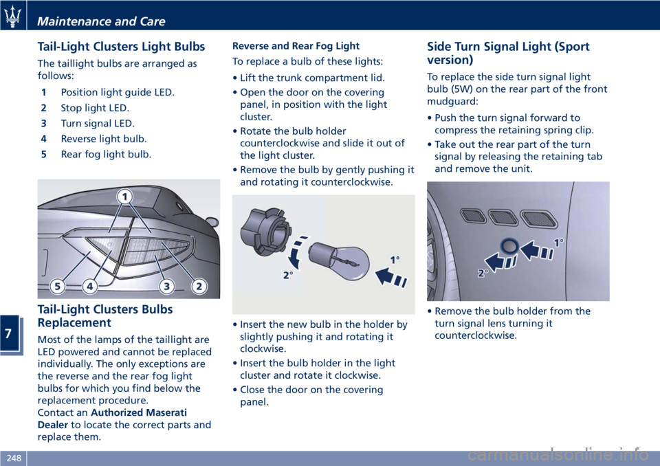
The taillight bulbs are arranged as
follows:
1Position light guide LED.
2Stop light LED.
3Turn signal LED.
4Reverse light bulb.
5Rear fog light bulb.
Tail-Light Clusters Bulbs
Replacement
Most of the lamps of the taillight are
LED powered and cannot be replaced
individually. The only exceptions are
the reverse and the rear fog light
bulbs for which you find below the
replacement procedure.
Contact anAuthorized Maserati
Dealerto locate the correct parts and
replace them.Reverse and Rear Fog Light
To replace a bulb of these lights:
• Lift the trunk compartment lid.
• Open the door on the covering
panel, in position with the light
cluster.
• Rotate the bulb holder
counterclockwise and slide it out of
the light cluster.
• Remove the bulb by gently pushing it
and rotating it counterclockwise.
• Insert the new bulb in the holder by
slightly pushing it and rotating it
clockwise.
• Insert the bulb holder in the light
cluster and rotate it clockwise.
• Close the door on the covering
panel.
Side Turn Signal Light (Sport
version)
To replace the side turn signal light
bulb (5W) on the rear part of the front
mudguard:
• Push the turn signal forward to
compress the retaining spring clip.
• Take out the rear part of the turn
signal by releasing the retaining tab
and remove the unit.
• Remove the bulb holder from the
turn signal lens turning it
counterclockwise.
Maintenance and Care
7
248
Page 253 of 286

• Extract the bulb from the holder by
turning it clockwise.
• Replace the bulb.
• Refit the bulb holder in the turn
signal lens turning it clockwise.
• Refit the turn signal in the seat of
the mudguard, inserting first the
retaining tab on the rear part of the
turn signal lens.• Press the front part of the turn
signal lens until hearing the spring
clip click into position.
CAUTION!
Proceed with care when removing the
side turn signal light to avoid
damaging to the vehicle body or the
turn signal itself.
Side Turn Signal Lights (MC
version)
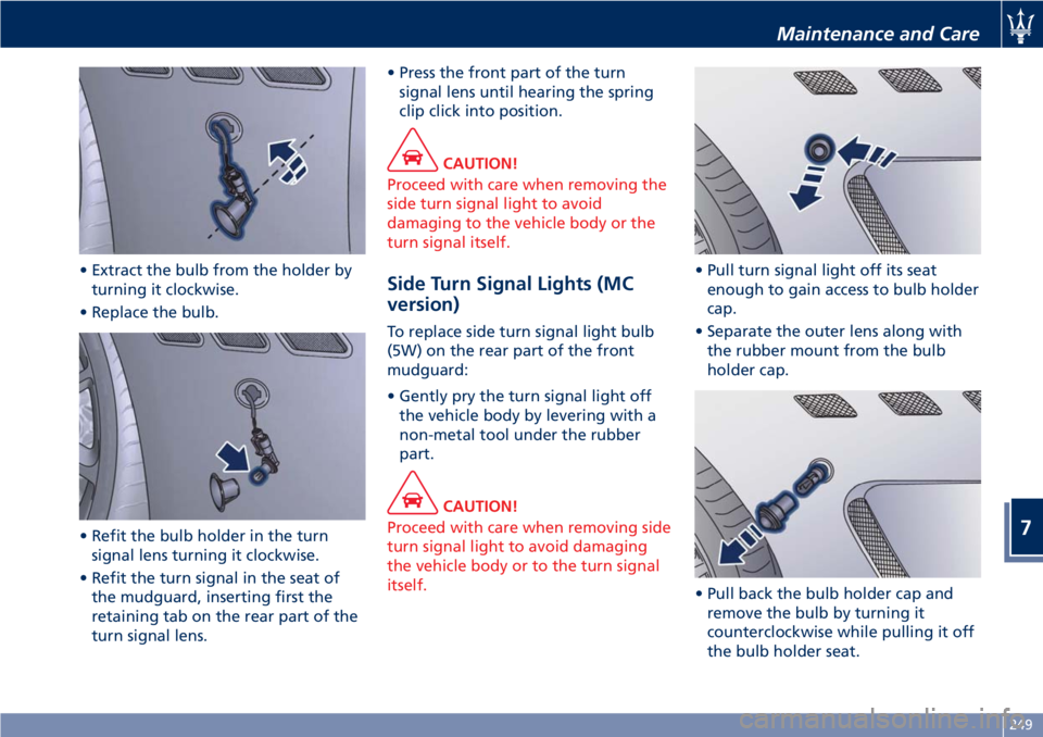
To replace side turn signal light bulb
(5W) on the rear part of the front
mudguard:
• Gently pry the turn signal light off
the vehicle body by levering with a
non-metal tool under the rubber
part.
CAUTION!
Proceed with care when removing side
turn signal light to avoid damaging
the vehicle body or to the turn signal
itself.
• Pull turn signal light off its seat
enough to gain access to bulb holder
cap.
• Separate the outer lens along with
the rubber mount from the bulb
holder cap.
• Pull back the bulb holder cap and
remove the bulb by turning it
counterclockwise while pulling it off
the bulb holder seat.
Maintenance and Care
7
249