2020 MASERATI GRANTURISMO engine
[x] Cancel search: enginePage 95 of 286

Rain Sensing Wipers
This feature detects moisture on the
windshield through an inside rearview
mirror integrated sensor.
The rain sensor adapts the frequency
of the windshield wiper strokes (in the
intermittent operation mode) to the
intensity of the rain.
All the other functions controlled by
the right-hand multifunction lever
(windshield wipers off, in continuous
slow and fast operation mode and in
temporary fast operation mode)
remain the same.
The rain sensor is activated
automatically by moving the
right-hand multifunction lever to
"AUTO" position. The sensor has a
setting range that varies progressively:
from the windshield wiper stationary
position - when the windshield is dry -
to the windshield wiper second speed
- in conditions of pouring rain.To regulate the frequency of
intermittent operation, with the
right-hand multifunction lever in
"AUTO" position, turn the end section
of the lever.
Rotating the end section clockwise,
intermittent operation varies from fast
intermittent wipe (max.) to slow
intermittent wipe (min).
If the engine is turned off during
automatic windshield wiper
operation, with the right-hand
multifunction lever in "AUTO"
position, to reactivate the function the
next time the engine is started, the
lever must be moved to "OFF" (stop
position) then back to "AUTO"
position.CAUTION!
• The rain sensing feature may not
function properly by ice or dried salt
water on the windshield.
• Use on the windshield of RainX
®or
products containing wax or silicone
may reduce rain sensor performance.
Rain Sensor Failure
When the rain sensor is activated, in
the event that it is malfunctioning, the
windshield wiper will be switched on
in intermittent operation mode and
the sensing range will be set by the
user, regardless of whether or not
there is rain on the windshield.
The
symbol appears on the
instrument cluster display.
In this case, we recommend that you
cut-out the rain sensor and turn on
the wiper, if necessary, in continuous
mode. Contact theAuthorized
Maserati Dealeras soon as possible.
Understanding the Vehicle
3
91
Page 96 of 286

Windshield Washers and
Headlight Washers
To use the washer, pull toward the
steering wheel the right-hand
multifunction lever (toward the
steering wheel) and hold it as long as
washer spray is desired.
If you activate the washer while the
windshield wiper control is in the
automatic intermittent range, the
wipers will operate for a few wipe
cycles after releasing the lever and
then resume the previously selected
intermittent interval.
If you activate the washer while the
windshield wiper is turned off (OFF)
the wipers will operate for three wipe
cycles and then turn off.WARNING!
•Do not start the windshield washer
during the cold months until the
windshield has warmed up. If it has
not warmed up, the liquid could
freeze on the glass and block your
view.
•Sudden loss of visibility through the
windshield could lead to a collision.
You might not see other vehicles or
other obstacles. To avoid sudden
icing of the windshield during
freezing weather, warm the
windshield with the defroster before
and during windshield washer use.
WARNING!
California Proposition 65
Operating, servicing and maintaining
a passenger vehicle or off-road vehicle
can expose you to chemicals including
such as, engine exhaust, carbon
monoxide, phthalates and lead, that
which are know to the State of
California to cause cancer and birth
defects or other reproductive harm. To
minimize exposure, avoid breathing
exhaust, do not idle the engine except
as necessary, service your vehicle in awell-ventilated area and wear gloves
or wash your hands frequently when
servicing your vehicle. For more
information go to:
www.P65Warnings.ca.gov/passenger-
vehicle
Headlight Washers
The right-hand multifunction lever
also operates the headlight washers
when the key in the ignition switch is
inMAR (ON)position and the
headlights are turned on.
The headlight washers will spray a
timed high pressure spray of washer
fluid when the windshield washer is
started.
The headlight washers are deactivated
if the vehicle speed exceeds 75 mph
(120 km/h).
Understanding the Vehicle
3
92
Page 97 of 286

Interior Features
Electric Power Outlets
The vehicle is equipped with two 12
Volt (13 Amp) electric power outlets.
One in passenger compartment on the
central console, under the cover with
armrest function, using the socket of
the cigarette lighter as power outlet
and one fitted in the trunk.
All power outlets are supplied only
when the engine is started or the key
in the ignition switch is turned inACC
orMAR (ON)position.
Power outlets are protected by a fuse.
Insert a cigarette lighter or accessory
plug into the power outlets to ensure
proper operation. Otherwise, check
the matching fuse integrity, see “Fuse
Replacement” in section
“Maintenance and Care” for further
information.
CAUTION!
• Do not plug in accessories that
exceed the maximum power of 160
Watts (13 Amps) at 12 Volts.
• Power outlets are designed for
accessory plugs only. Do not insert
any other object in the power
outlets as this will damage the outletand blow the fuse. Damages caused
by improper use of the power outlet
are not covered by the New Vehicle
Limited Warranty.
WARNING!
To avoid serious injury or death:
•Only devices designed for use in this
type of outlet should be inserted
into any 12 Volt outlet.
•Replacing the fuses that protect
power outlets with others of higher
amperage, there is the risk of fire.
•Do not touch with wet hands.
•If this outlet is mishandled, it may
cause an electric shock and failure.
Power Outlet on Central Console
To access the power outlet on the
central console lift the cover with
armrest function by pushing the inside
handle.
Remove the cigarette lighter and use
its socket as power outlet.
WARNING!
High power consumption items
plugged into this outlet for longperiods may discharge the battery
and/or prevent the engine from
starting.
Power Outlet inside the Trunk
The power outlet is positioned on the
left side of the trunk compartment.
Understanding the Vehicle
3
93
Page 103 of 286

General Information
While programming HomeLink®,itis
advisable to disconnect the drive
motor of the gate/door to be remote
controlled, since the numerous driving
pulses launched for this operation
might damage it.
If the battery fails or is disconnected,
the stored settings are not deleted.
If the gate/door was manufactured
prior to April 1982 (not equipped with
safety systems or automatic stop in the
event of an obstacle in the range of
action), the gate/door cannot be
controlled by HomeLink
®.
If you have questions, call (800)
355-3515.
WARNING!
California Proposition 65
Operating, servicing and maintaining
a passenger vehicle or off-road vehicle
can expose you to chemicals including
such as, engine exhaust, carbon
monoxide, phthalates and lead, that
which are know to the State of
California to cause cancer and birth
defects or other reproductive harm. To
minimize exposure, avoid breathing
exhaust, do not idle the engine except
as necessary, service your vehicle in awell-ventilated area and wear gloves
or wash your hands frequently when
servicing your vehicle. For more
information go to:
www.P65Warnings.ca.gov/passenger-
vehicle
Programming
• Press and hold buttons "1" and "3".
• After about 20 seconds, the LED
starts flashing.
• Release the buttons.
• Hold the remote control for the
device to be controlled close to the
HomeLink
®control panel (0-30 cm/
0-12 in).
• Simultaneously press and hold the
button on the hand-held remote
control and one of the three
HomeLink
®buttons "1", "2" or "3".
• Successful programming is signaled
by the LED flashing faster.
• Release the buttons.
To program the other buttons, repeat
the operations skipping the first three
steps.
Use
• When the signal of the device to be
activated reaches its operatingrange, press the dedicated
HomeLink
®button.
• The LED remains on while the signal
is being transmitted.
The devices controlled through the
HomeLink
®function can always be
activated using the original remote
controls.
Should the so programmed
HomeLink
®not activate the system to
be controlled, this may be due to the
fact that this system is controlled by a
remote control with a rolling code.
A rolling activation code can be
recognized in the following ways:
• consulting the instruction manual
provided with the device to be
controlled;
• despite the fact that the HomeLink
®
programming procedure has been
carried out correctly, the HomeLink®
function does not activate the
device;
• holding the dedicated HomeLink
®
button pressed down, the LED
briefly flashes fast and then remains
on for 2 seconds; this sequence is
repeated for about 20 seconds.
Understanding the Vehicle
3
99
Page 107 of 286

Sport Skyhook Suspension
(for versions/markets,
where provided)
The electronic system controlling the
vehicle suspension uses the
sophisticated on board sensors and is
aimed at optimizing vehicle
performance.
The system is capable of constantly
monitoring suspension damping by
means of the actuator fitted on each
shock absorber (Skyhook type). This
way, the shock absorber setting is
suited to the road surface conditions
and vehicle dynamics, thus improving
passenger comfort and road-holding.
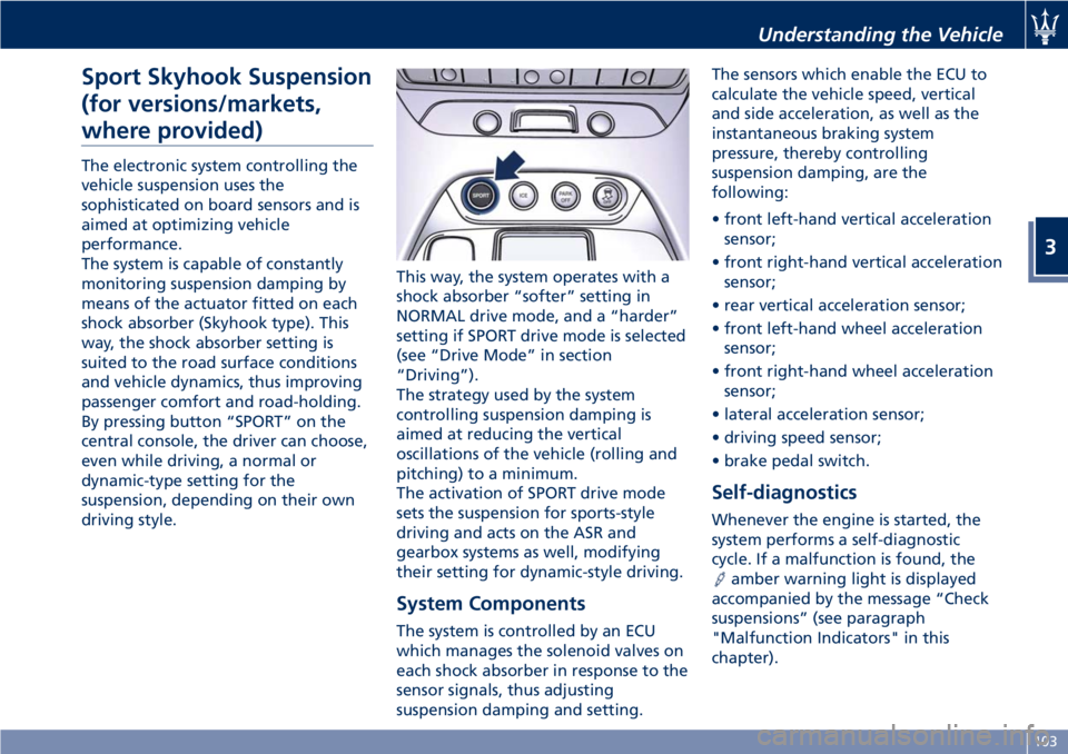
By pressing button “SPORT” on the
central console, the driver can choose,
even while driving, a normal or
dynamic-type setting for the
suspension, depending on their own
driving style.This way, the system operates with a
shock absorber “softer” setting in
NORMAL drive mode, and a “harder”
setting if SPORT drive mode is selected
(see “Drive Mode” in section
“Driving”).
The strategy used by the system
controlling suspension damping is
aimed at reducing the vertical
oscillations of the vehicle (rolling and
pitching) to a minimum.
The activation of SPORT drive mode
sets the suspension for sports-style
driving and acts on the ASR and
gearbox systems as well, modifying
their setting for dynamic-style driving.
System Components
The system is controlled by an ECU
which manages the solenoid valves on
each shock absorber in response to the
sensor signals, thus adjusting
suspension damping and setting.The sensors which enable the ECU to
calculate the vehicle speed, vertical
and side acceleration, as well as the
instantaneous braking system
pressure, thereby controlling
suspension damping, are the
following:
• front left-hand vertical acceleration
sensor;
• front right-hand vertical acceleration
sensor;
• rear vertical acceleration sensor;
• front left-hand wheel acceleration
sensor;
• front right-hand wheel acceleration
sensor;
• lateral acceleration sensor;
• driving speed sensor;
• brake pedal switch.
Self-diagnostics
Whenever the engine is started, the
system performs a self-diagnostic
cycle. If a malfunction is found, the
amber warning light is displayed
accompanied by the message “Check
suspensions” (see paragraph
"Malfunction Indicators" in this
chapter).
Understanding the Vehicle
3
103
Page 108 of 286

Calibration Selection
The driver can select, in relation to
road surface conditions, vehicle speed,
driving style and comfort, one of the
two calibration levels provided by the
system: normal or sports-style.
•Normal calibration, active when
SPORT drive mode is disabled
("SPORT" button not pressed), favors
comfort and higher driving stability
with low and average grip
conditions.
•Sport-style calibration, active when
SPORT drive mode is enabled
("SPORT" button pressed) , favors
wheel drive and permits a
dynamic-style driving with optimal
road holding.
Whenever the engine is started, the
system automatically activates
NORMAL drive mode, even if SPORT
drive mode was selected before the
engine was last turned off.
The sport-style calibration can be
selected only with the key in the
ignition switch inMAR (ON)position
and it is enabled by pressing button
"SPORT", even while driving.
When SPORT drive mode is activated,
the word “SPORT” on the instrument
cluster display and the LED on the
button illuminate.WARNING!
SPORT drive mode should not be
activated if the road surface is rough
or slippery.
The electronic suspension control
system works in combination with the
ESC system.
When the suspension is set to normal
calibration, stability is increased under
medium and low grip conditions, while
when it is set to sport-style calibration,
the ESC system optimizes a sportier
driving.
WARNING!
In low- and medium-grip conditions
(e.g., rain, snow, ice, sand, etc.) it is
advisable not to use SPORT drive
mode, even with the ESC system
enabled.
Malfunction Indicators
If one or more electric components in
the system prove to be malfunctioning
while driving, the ECU illuminates the
amber warning light accompanied
by the message “Check suspensions”
on the display. In addition, the ECU
calibrates the shock absorbers to apreset value, thus ensuring a safe
vehicle set up.
Should the malfunction involve one
shock absorber only, this will no longer
be controlled by the ECU and will
therefore remain set as it was when
the fault occurred. It is therefore
possible for one of the four shock
absorbers to work with a fixed
calibration, different from that of the
other ones.
In any case, safe and secure vehicle
driving is always ensured at low
speeds.
CAUTION!
In the event of a malfunction in the
suspension control electronic system,
which will be indicated by the
illumination of the amber warning
light on the display while driving, keep
a moderate speed and have the vehicle
checked as soon as possible by an
Authorized Maserati Dealer.
If a malfunction occurs while driving,
and this is signaled by the illumination
of the
amber warning light on the
display, it is advisable to stop the
vehicle as soon as possible, turn the
key in the ignition switch toSTOP
(OFF)position and then restart the
engine.
Understanding the Vehicle
3
104
Page 113 of 286

Warning and Indicator Lights
on Analog Instruments
Low Fuel Indicator on Fuel Gage
The illumination of the red indicator
inside the gage indicates that there
are approx. 4.7 Gallons (18 liters) of
fuel in the tank.
If the pointer positions on "0"
(beginning of scale) and the fuel
reserve indicator flashes, it means that
there is a system malfunction.
In this case, contact anAuthorized
Maserati Dealerto have the system
checked.
Telltales on Speedometer
Following telltales are displayed on
the fuel level gage and speedometer,
and related messages are visible for 10
seconds on the central sector of the
display, unless otherwise indicated.The telltales indicated with (*) are also
displayed on the TFT display (see “TFT
Display” paragraph in this chapter).
Charging System Warning Light
This warning light shows the
status of the electrical
charging system. If the light
stays on or comes on while
driving, turn off some of the vehicle's
non-essential electrical devices or
increase engine speed (if at idle). If
the charging system warning light
remains on, it means that the vehicle
is experiencing a problem with the
charging system. Require IMMEDIATE
service at anAuthorized Maserati
Dealer.
If jump starting is required, refer to
“Jump Start Procedures” in section “In
an Emergency”.Malfunction Indicator Light (*)
The Malfunction Indicator
Light (MIL) is part of an
onboard diagnostic system
that monitors engine and
automatic transmission control
systems.
Under normal conditions, this
indicator light should switch on when
the key in the ignition switch is in
MAR (ON)position and switch off
soon after the engine is started.
This is a sign of the indicator light
working properly. If the indicator
remains lighted up or switches on
while driving, there is a failure in the
fuel supply/ignition and emission
control systems.
The failure could cause high exhaust
emissions, loss of performance, poor
vehicle handling and high
consumption levels.
Under these conditions you can
proceed slowly without forcing the
engine or driving at high speeds.
The indicator light will switch off if
the problem is solved.
The error will be registered by the
system in any case.
Dashboard Instruments and Controls
4
109
Page 114 of 286

CAUTION!
• When the key on the key in the
ignition switch is in theMAR (ON)
position and if the indicator light
does not switch on or if it switches
on while driving, contact an
Authorized Maserati Dealeras soon
as possible.
• Prolonged driving with the MIL on
could cause damage to the engine
control system. It also could affect
fuel economy and drivability. If the
MIL is flashing, severe catalytic
converter damage and power loss
will soon occur. Immediate service is
required.
Parking Lights Indicator
With the key removed from
the ignition switch, it indicates
that the parking lights are on.
Transmission Failure Warning Light (*)
Depending on the message
displayed it signals:
• a transmission failure. If the
failure permits, slowly drive
to the nearestAuthorized
Maserati Dealer;• a too high temperature of the
transmission oil. In this case, slow
down until the temperature goes
down to the normal values for use
(the warning light goes off).
For further information see chapter
“Automatic Transmission” in section
“Driving”.
CAUTION!
Continuous driving with the
transmission temperature warning
light illuminated will eventually cause
severe transmission damage or failure.
WARNING!
If the transmission temperature
warning light is illuminated and you
continue operating the vehicle, in
some circumstances you could cause
the fluid to boil over, come in contact
with hot engine or exhaust
components and cause a fire.
High Beam Indicator
This indicator lights up when
the high beams are switched
on or when blinking.Low Oil Pressure Warning Light (*)
Under normal conditions, the
warning light illuminates
when the key in the ignition
switch is turned toMAR (ON)
position and goes off as soon as the
engine is started.
If the warning light stays or turns on
while driving, the engine oil pressure is
too low. The warning light is combined
with a displayed message. In this case,
turn the engine off immediately and
carry out the necessary checks.
Do not operate the vehicle until the
problem has been solved. This light
does not indicate the oil level. The
engine oil level must be checked with
the dipstick located under the hood
(see “Maintenance Procedures” in
section “Maintenance and Care”).
If the problem persists, contact an
Authorized Maserati Dealer.
Headlight On Indicator
This indicator will illuminate
when the position lights or
headlights are turned on.
For further details, see
“Lights” in section “Understanding the
Vehicle”.
Dashboard Instruments and Controls
4
110