2020 MASERATI GRANTURISMO reset
[x] Cancel search: resetPage 162 of 286

TripA-TripB
In these screens are displayed the
detailed data on "Trip A" and "Trip B".
These data are also displayed in the
Trip pages of the instrument cluster
(see paragraph "TFT Display: Screen
Pages" of chapter "Instrument
Cluster" of this section).
For each of these submenus the screen
will display the following data:
• Distance traveled.
• Average fuel consumption.
• Average speed.
• Duration.
The unit for these submenus can be
adjusted by the user from MTC+
setting menu (see "MTC+ Settings" in
this section).
In addition to these, there is also the
"reset" softkey to reset the "Trip A"
and/or the "Trip B".
Service
When checking this item, the MTC+
displays mileage and days remaining
before the execution of schedule
maintenance service and warns when
it is expired.For further details, see “Scheduled
Maintenance Service” in section
“Maintenance and Care”.
Driving
5
158
Page 180 of 286
the speed stored. Every time rotating
section is reset, the speed is increased
or decrease by approx. 0.6 mph (1
Km/h). Keep the rotating section
turned to vary the speed
continuously. When a new speed is
reached, it will automatically remain
constant.
• Button "RCL" at end of left
multifunction lever is used to resume
the speed stored.
NOTE:
•When the key in the ignition switch
is turned toSTOP (OFF)position or
ON/OFF switch is in the "OFF"
position, the speed stored is erased
and the system deactivated.
•The CC must be deactivated when
not in use.
WARNING!
Leaving the Cruise Control system on
when not in use is dangerous. You
could accidentally set the system or
cause it to go faster than you want.
Always leave the CC off when you are
not using it.
Storing a Speed
Turn the ON/OFF switch to "ON" and
reach the desired speed driving
normally. Turn the rotating section in
the middle of the left multifunction
lever to "+" for at least 3 seconds and
then release it.
The vehicle speed is stored and the
accelerator pedal can be released.
The vehicle will proceed at the
constant speed stored until the brake
pedal is pressed.
If necessary, (for example, to pass
another vehicle), you can accelerate by
simply pressing the accelerator pedal.
Afterward, when you release the
accelerator pedal, the vehicle will
return to the speed previously stored.
Resuming the Speed Stored
If the CC has been deactivated after
braking, the speed previously stored
can be resumed as follows:
• gradually accelerate until you reach a
speed close to that stored;
• engage the gear selected when the
speed was stored (4th, 5th or 6th
gear);
• press button "RCL".
Increasing the Speed Stored
The speed stored can be increased in
two ways:• by pressing the accelerator and then
storing the new speed reached (turn
the rotating section in the middle of
the left multifunction lever for more
than 3 seconds); or
• by turning the rotating section to
position "+": each impulse
transmitted by the rotating section
will cause a slight increase in speed
(about 0.6 mph/1 Km/h), whereas a
constant pressure on the same
rotating section will cause a
continuous increase in speed. When
the rotating section is released, the
new speed will be automatically
stored in the memory.
Decreasing the Speed Stored
The speed stored can be reduced in
two ways:
• by deactivating the CC, pressing the
brake pedal and then storing the
new speed (turning the rotating
section to position “+” for at least 3
seconds); or
• by keeping the rotating section
turned to position “-” until reaching
the new speed, which will be stored
automatically.
Resetting the Speed Stored
The speed stored is automatically
reset:
Driving
5
176
Page 221 of 286
Position and release the parking
brake (see “ Transmission Manual
Release of P (Park) position” and
“Emergency Release of the Parking
Brake” in this section).
•If the vehicle battery is still charged,
turn off the engine and disengage
the parking brake manually (if
automatically engaged) by using the
command at the side of the
transmission shift lever (see “Parking
Brake” chapter in section “Driving”).
Shift then manually the transmission
out of P (Park) as described in
“Transmission Manual Release of P
(Park) Position” chapter of this
section. If you need to use the
accessories (wipers, defrosters, etc.)
while being towed, the key in the
ignition switch must be turned in
MAR (ON)position, do not use the
ACCposition.
Vehicle Towing Conditions
Maserati only allows vehicle towing
either on a flatbed or with all four
wheels off the ground.
If flatbed equipment is not available,
and the transmission is still operable,
the vehicle may be flat towed (with all
four wheels on the ground) under the
following conditions.• The shift lever must be in N
(Neutral).
• The distance to be traveled must not
exceed 30 mi (50 km ).
• The towing speed must not exceed
30 mph (50 km/h).
If the transmission is not operable, or
the vehicle must be towed faster than
30 mph (50 km/h ) or farther than 30
mi (50 km) (for example on a
highway), tow with the rear driving
wheels off the ground and on a
platform of a rescue vehicle, or with
the rear wheels raised using a wheel
lift.
CAUTION!
If you have to tow the vehicle with 2
wheels raised, ensure that the key in
the ignition switch is in theSTOP (OFF)
position. If this is not observed, when
the ESC is active, the ECU will store a
malfunction and the relative indicator
light
will illuminate on the
instrument cluster display. This
requires the intervention of an
Authorized Maserati Dealerto reset
the system.
Use the Vehicle Tow Hook of
the Tool Kit
CAUTION!
The tow hook should only be used for
towing the car on flat roads. Do not
use the tow hook to remove the car
that is stuck on off road stretches.
The tow hook can also be used to tow
the vehicle on the platform of a tow
truck.
It is necessary to inform the operators
of the rescue vehicle about the vehicle
minimum height to avoid, during its
loading, any contact of the lower ends
of the front or rear bumper with the
tow truck loading ramp.
The tow hook is contained in the tool
kit (see “Tool Kit” in this section) and
must be screwed in its seat accessible
behind the front grille, right-hand
side.
• Remove the protective cap by
levering with the tip of a screwdriver
in the point shown in picture.
In an Emergency
6
217
Page 222 of 286
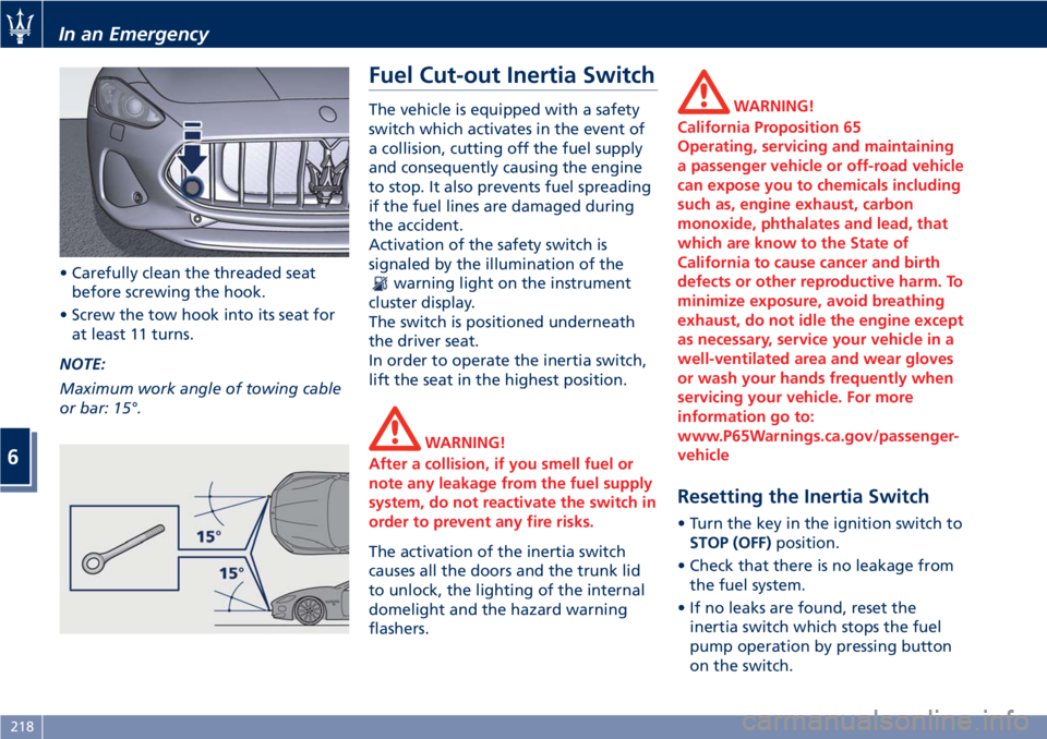
• Carefully clean the threaded seat
before screwing the hook.
• Screw the tow hook into its seat for
at least 11 turns.
NOTE:
Maximum work angle of towing cable
or bar: 15°.
Fuel Cut-out Inertia Switch
The vehicle is equipped with a safety
switch which activates in the event of
a collision, cutting off the fuel supply
and consequently causing the engine
to stop. It also prevents fuel spreading
if the fuel lines are damaged during
the accident.
Activation of the safety switch is
signaled by the illumination of the
warning light on the instrument
cluster display.
The switch is positioned underneath
the driver seat.
In order to operate the inertia switch,
lift the seat in the highest position.
WARNING!
After a collision, if you smell fuel or
note any leakage from the fuel supply
system, do not reactivate the switch in
order to prevent any fire risks.
The activation of the inertia switch
causes all the doors and the trunk lid
to unlock, the lighting of the internal
domelight and the hazard warning
flashers.
WARNING!
California Proposition 65
Operating, servicing and maintaining
a passenger vehicle or off-road vehicle
can expose you to chemicals including
such as, engine exhaust, carbon
monoxide, phthalates and lead, that
which are know to the State of
California to cause cancer and birth
defects or other reproductive harm. To
minimize exposure, avoid breathing
exhaust, do not idle the engine except
as necessary, service your vehicle in a
well-ventilated area and wear gloves
or wash your hands frequently when
servicing your vehicle. For more
information go to:
www.P65Warnings.ca.gov/passenger-
vehicle
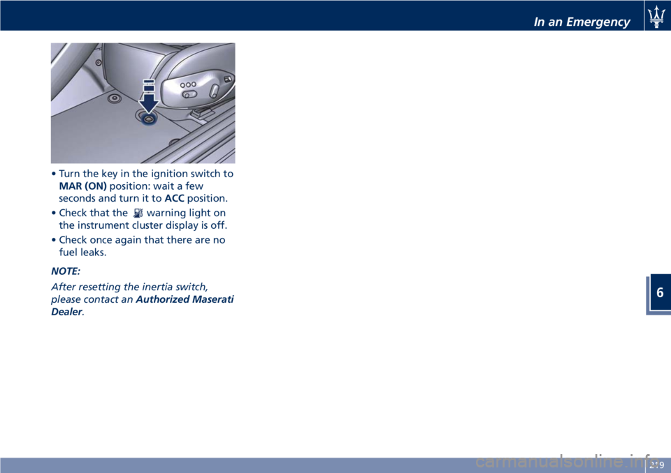
Resetting the Inertia Switch
• Turn the key in the ignition switch to
STOP (OFF)position.
• Check that there is no leakage from
the fuel system.
• If no leaks are found, reset the
inertia switch which stops the fuel
pump operation by pressing button
on the switch.
In an Emergency
6
218
Page 223 of 286
• Turn the key in the ignition switch to
MAR (ON)position: wait a few
seconds and turn it toACCposition.
• Check that the
warning light on
the instrument cluster display is off.
• Check once again that there are no
fuel leaks.
NOTE:
After resetting the inertia switch,
please contact anAuthorized Maserati
Dealer.
In an Emergency
6
219
Page 227 of 286

Once the set limit in kilometers or the
expiry date is reached, every time the
instrument cluster is turned on
thereafter, the message “Service
coupon expired” will be displayed.Selecting the function “Service” in the
“Trip” menu of the MTC+, you can
display the next service deadline (see
“Onboard Computer (Trip)” in section
"Driving"). The residual mileage left
to the service deadline is always
indicated. The days remaining before
the scheduled service date instead, are
only indicated starting from the 511th
day (approximately 17 months).
NOTE:
Every time the battery is disconnected,
the date and time must be set (see
"MTC+ Settings" in section
"Dashboard Instruments and
Controls").
CAUTION!
• Failure to reset the system may cause
it to malfunction and indicate wrong
maintenance service intervals.
• If you incorrectly set a date earlier
than the last service coupon, the
system updates the indication
“Scheduled service within... days”
automatically entering a later date
considering the maximum number of
days allowable for the next service
coupon.
Maintenance and Care
7
223
Page 283 of 286
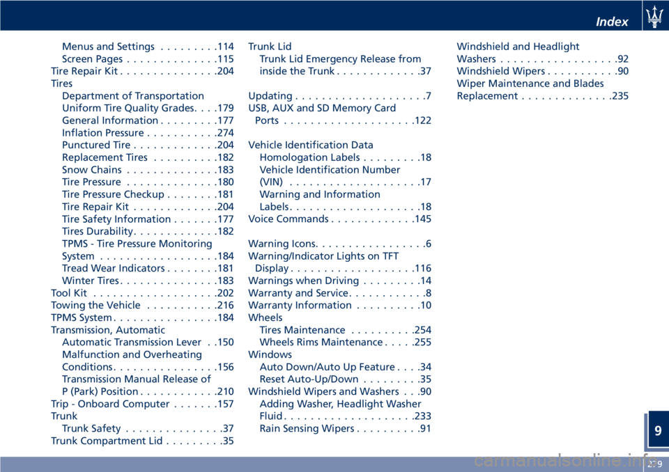
Menus and Settings.........114
Screen Pages..............115
Tire Repair Kit...............204
Tires
Department of Transportation
Uniform Tire Quality Grades. . . .179
General Information.........177
Inflation Pressure...........274
Punctured Tire.............204
Replacement Tires..........182
Snow Chains..............183
Tire Pressure..............180
Tire Pressure Checkup........181
Tire Repair Kit.............204
Tire Safety Information.......177
Tires Durability.............182
TPMS - Tire Pressure Monitoring
System..................184
Tread Wear Indicators........181
Winter Tires...............183
ToolKit ...................202
Towing the Vehicle...........216
TPMS System................184
Transmission, Automatic
Automatic Transmission Lever . .150
Malfunction and Overheating
Conditions................156
Transmission Manual Release of
P (Park) Position............210
Trip - Onboard Computer.......157
Trunk
Trunk Safety...............37
Trunk Compartment Lid.........35Trunk Lid
Trunk Lid Emergency Release from
inside the Trunk.............37
Updating....................7
USB, AUX and SD Memory Card
Ports....................122
Vehicle Identification Data
Homologation Labels.........18
Vehicle Identification Number
(VIN)....................17
Warning and Information
Labels....................18
Voice Commands.............145
Warning Icons.................6
Warning/Indicator Lights on TFT
Display...................116
Warnings when Driving
.........14
Warranty and Service............8
Warranty Information..........10
Wheels
Tires Maintenance..........254
Wheels Rims Maintenance.....255
Windows
Auto Down/Auto Up Feature....34
Reset Auto-Up/Down.........35
Windshield Wipers and Washers . . .90
Adding Washer, Headlight Washer
Fluid....................233
Rain Sensing Wipers..........91Windshield and Headlight
Washers..................92
Windshield Wipers...........90
Wiper Maintenance and Blades
Replacement..............235
Index
9
279