Page 153 of 286

Engine Start Failure
CAUTION!
• Do not attempt to push or tow your
vehicle to get it started. Vehicles
equipped with an automatic
transmission cannot be started this
way.
• If the vehicle battery is dead, booster
cables may be used to obtain a start
from a booster battery or the
battery in another vehicle. This type
of start can be dangerous if done
improperly. See “Auxiliary Jump
Start Procedure” in section “In an
Emergency” for further information.
Starting by cold engine
Start-off slowly, avoiding sudden
acceleration and rev the engine up at
low medium speeds. High-
performance driving should be
avoided until the engine temperature
reaches 65-70°C (149-158°F).
Engine Turn-Off
• Place the shift lever in P (Park) (see
“Automatic Transmission” in this
section).
• With the engine at idle, turn the key
in the ignition switch toSTOP (OFF)position. A burst on the accelerator
pedal before turning off the engine
has no purpose and increases fuel
consumption.
WARNING!
Never leave a vehicle out of the P
(Park) position, as it could move.
The key can only be removed from the
ignition switch when the transmission
is in P (Park) position and within 30
seconds after turning the key toSTOP
(OFF)position. If you do not remove
the key within 30 seconds, you will
need to turn it back toMAR (ON)and
then toSTOP (OFF)position to have a
further 30 seconds within which to
remove the key from the ignition
switch.
In the event that the key unlocking
system fails or if it is not possible to
shift the transmission to P (Park)
position, to remove the key you must
turn it toSTOP (OFF)position, then
remove the cap shown in picture using
a pen or sufficiently pointed tool.
Then press the button just uncovered
and at the same time extract the key
from the ignition switch. Once the key
has been removed, refit the removed
cap.
Driving
5
149
Page 250 of 286
Fuses in Trunk Compartment
• To access the fuses, remove the floor
panel.
• Remove the inside covering panel of
the battery compartment.
There are two control boxes.
• To access the fuses inside the control
boxes, remove the covers by levering
up the fastening tabs.The following table points out the
position as featured in the picture, the
type and function of the fuses
included in these control boxes.Trunk Compartment FusesPos. Amp. –
ColorSystem / Component
F25 - Not used
F26 - Not used
F27 - Not used
F28 - Not used
F29 - Not used
F53 - Not used
F54 30 A –
GreenHI-Fi amplifier
F55 - Not used
F56 10 A –
Red+30 NAG, NTV,
Harman tuner, MTC+
(Japan)
F57 - Not used
F58 7.5 A –
BrownRH Reverse from T23
F59 - Not used
F60 7.5 A –
BrownNSP
F61 7.5 A –
BrownT24 third stop
F62 20 A –
YellowNCA
F63 15 A –
BlueFuel flap T25 relay,
+30 Battery charge
Maintenance and Care
7
246
Page 251 of 286

Pos. Amp. –
ColorSystem / Component
F64 - Not used
F65 10 A –
RedKey-Lock solenoid
F66 20 A –
YellowFuel pumps
F67 - Not used
F68 - Not used
F69 - Not used
F77 - Not used
F78 20 A –
YellowPower outlet
F79 - Not used
F80 25 A –
WhiteBass boxBulb Replacement
The signal failure of an external light
(turn signal, low beam and high beam,
license plate light, reverse light, brake
light and rear fog light) is
communicated to the instrument
cluster that displays on the TFT screen
the
oramber warning light
and a text message indicating which
light is faulty.
Front Headlights
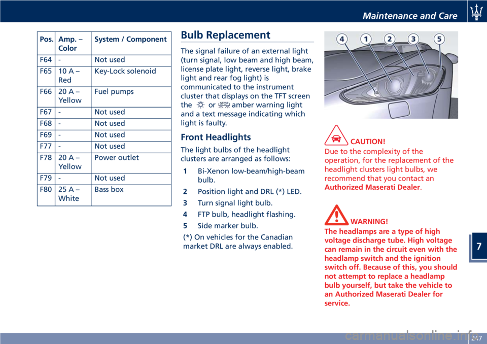
The light bulbs of the headlight
clusters are arranged as follows:
1Bi-Xenon low-beam/high-beam
bulb.
2Position light and DRL (*) LED.
3Turn signal light bulb.
4FTP bulb, headlight flashing.
5Side marker bulb.
(*) On vehicles for the Canadian
market DRL are always enabled.
CAUTION!
Due to the complexity of the
operation, for the replacement of the
headlight clusters light bulbs, we
recommend that you contact an
Authorized Maserati Dealer.
WARNING!
The headlamps are a type of high
voltage discharge tube. High voltage
can remain in the circuit even with the
headlamp switch and the ignition
switch off. Because of this, you should
not attempt to replace a headlamp
bulb yourself, but take the vehicle to
an Authorized Maserati Dealer for
service.
Maintenance and Care
7
247
Page 273 of 286
CAUTION!
• Actual fuel economy results will vary
for many reasons, including driving
conditions and how you drive and
maintain your vehicle.
• The type of route, traffic and
weather conditions, driving style,
general condition of the vehicle,
equipment/accessories in the vehicle,
use of the air conditioning system,
vehicle load and other items or
situations which may negatively
affect the vehicle aerodynamics or
wind resistance lead to consumption
ratios differing from the indicated
ones.
Technical Data
NOTE:
The technical data, values and
specifications in this Owner’s Manual
are provided as guidance only. The
vehicle specific data can deviate from
the information provided, for
example, as a result of optional or
special equipment ordered with the
vehicle, vehicle loads, and country
specific measurement methods.
Features and Specifications
8
269