2020 MASERATI GRANTURISMO CONVERTIBLE door lock
[x] Cancel search: door lockPage 167 of 296
pedal pressed. To move the shift lever
from P (Park) position to any other
position, the engine must be switched
on. The engine can be regularly
started in P (Park) range. Never
attempt to use P (Park) while the
vehicle is in motion.
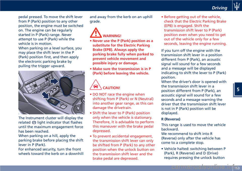
When parking on a level surface, you
may place the shift lever in the P
(Park) position first, and then apply
the electronic parking brake by
pulling the trigger upward.
The Instrument cluster will display the
related
light indicator that flashes
until the maximum engagement force
has been reached.
When parking on a hill, apply the
parking brake before placing the shift
lever in P (Park).
For enhanced security, turn the front
wheels toward the kerb on a downhilland away from the kerb on an uphill
grade.
WARNING!
•Never use the P (Park) position as a
substitute for the Electric Parking
Brake (EPB). Always apply the
parking brake fully when parked to
prevent vehicle movement and
possible injury or damage.
•Make sure the transmission is in P
(Park) before leaving the vehicle.
CAUTION!
• DO NOT race the engine when
shifting from P (Park) or N (Neutral)
into another gear range, as this can
damage the drivetrain.
• Shift the lever to P (Park) position
only when the vehicle is stationary.
Therefore, it is advisable to perform
this maneuver with the brake pedal
depressed.
• To prevent accidental engagement,
the transmission shift lever can only
be shifted from P (Park) to any other
position when the unlock button on
the transmission shift lever and the
brake pedal are depressed.• Before getting out of the vehicle,
check that the Electric Parking Brake
(EPB) is engaged. Shift the
transmission shift lever to P (Park)
position even when you need to get
out of the vehicle only for a few
seconds, leaving the engine running.
If you turn off the engine with the
transmission shift lever in a position
different from P (Park), an acoustic
signal will sound for a few seconds
and a message will be displayed
indicating to shift the lever to P (Park)
position.
When the driver’s door is opened with
the transmission shift lever in a
position different from P (Park), an
acoustic signal will sound for a few
seconds and a message warning the
driver that the transmission shift lever
is not in P (Park) position will be
displayed.
R (Reverse)
This range is used to move the vehicle
backward.
We recommend to shift into R
(Reverse) only after the vehicle has
come to a complete stop.
• Vehicle halted: switching between P
(Park), R (Reverse) and D (Drive)
requires pressing the unlock button
Driving
5
163
Page 206 of 296
Refueling
Fuel Filler Neck Access
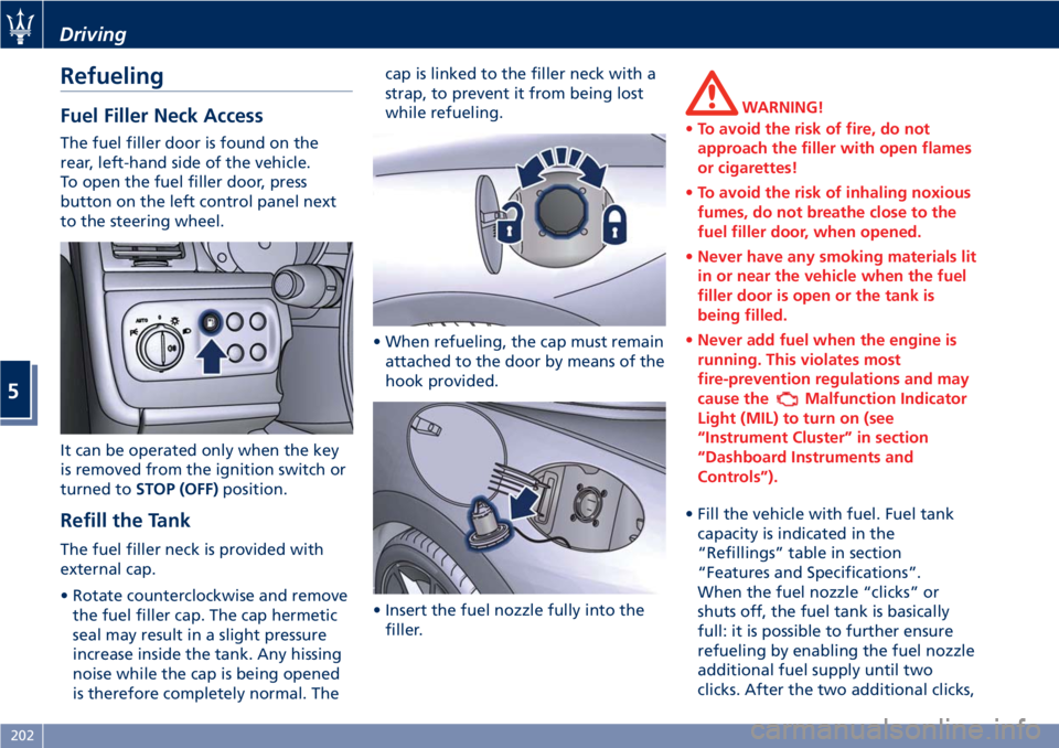
The fuel filler door is found on the
rear, left-hand side of the vehicle.
To open the fuel filler door, press
button on the left control panel next
to the steering wheel.
It can be operated only when the key
is removed from the ignition switch or
turned toSTOP (OFF)position.
Refill the Tank
The fuel filler neck is provided with
external cap.
• Rotate counterclockwise and remove
the fuel filler cap. The cap hermetic
seal may result in a slight pressure
increase inside the tank. Any hissing
noise while the cap is being opened
is therefore completely normal. Thecap is linked to the filler neck with a
strap, to prevent it from being lost
while refueling.
• When refueling, the cap must remain
attached to the door by means of the
hook provided.
• Insert the fuel nozzle fully into the
filler.
WARNING!
•To avoid the risk of fire, do not
approach the filler with open flames
or cigarettes!
•To avoid the risk of inhaling noxious
fumes, do not breathe close to the
fuel filler door, when opened.
•Never have any smoking materials lit
in or near the vehicle when the fuel
filler door is open or the tank is
being filled.
•Never add fuel when the engine is
running. This violates most
fire-prevention regulations and may
cause the
Malfunction Indicator
Light (MIL) to turn on (see
“Instrument Cluster” in section
“Dashboard Instruments and
Controls”).
• Fill the vehicle with fuel. Fuel tank
capacity is indicated in the
“Refillings” table in section
“Features and Specifications”.
When the fuel nozzle “clicks” or
shuts off, the fuel tank is basically
full: it is possible to further ensure
refueling by enabling the fuel nozzle
additional fuel supply until two
clicks. After the two additional clicks,
Driving
5
202
Page 207 of 296
the amount of fuel allowed by the
system is very low, we recommend
therefore not to persist further.
• Wait approximately 10 seconds
before removing the fuel nozzle in
order to ensure completed supply of
residual fuel and restrict the risk of
fouling the fuel filler door area.
• Remove the fuel nozzle.
• Insert the cap on the fuel filler neck.
• Tighten the cap, turning it clockwise
until it stops.
• Close the fuel tank door.
CAUTION!
To avoid fuel spillage and overfilling,
do not “top off” the fuel tank after
filling.
Emergency Fuel Filler Door
Release
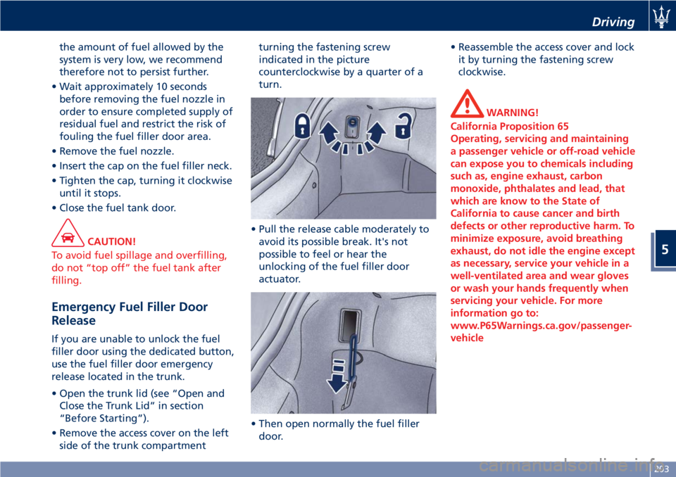
If you are unable to unlock the fuel
filler door using the dedicated button,
use the fuel filler door emergency
release located in the trunk.
• Open the trunk lid (see “Open and
Close the Trunk Lid” in section
“Before Starting”).
• Remove the access cover on the left
side of the trunk compartmentturning the fastening screw
indicated in the picture
counterclockwise by a quarter of a
turn.
• Pull the release cable moderately to
avoid its possible break. It's not
possible to feel or hear the
unlocking of the fuel filler door
actuator.
• Then open normally the fuel filler
door.• Reassemble the access cover and lock
it by turning the fastening screw
clockwise.
WARNING!
California Proposition 65
Operating, servicing and maintaining
a passenger vehicle or off-road vehicle
can expose you to chemicals including
such as, engine exhaust, carbon
monoxide, phthalates and lead, that
which are know to the State of
California to cause cancer and birth
defects or other reproductive harm. To
minimize exposure, avoid breathing
exhaust, do not idle the engine except
as necessary, service your vehicle in a
well-ventilated area and wear gloves
or wash your hands frequently when
servicing your vehicle. For more
information go to:
www.P65Warnings.ca.gov/passenger-
vehicle
Driving
5
203
Page 233 of 296
Use the Vehicle Tow Hook of
the Tool Kit
CAUTION!
The tow hook should only be used for
towing the car on flat roads. Do not
use the tow hook to remove the car
that is stuck on off road stretches.
The tow hook can also be used to tow
the vehicle on the platform of a tow
truck.
It is necessary to inform the operators
of the rescue vehicle about the vehicle
minimum height to avoid, during its
loading, any contact of the lower ends
of the front or rear bumper with the
tow truck loading ramp.
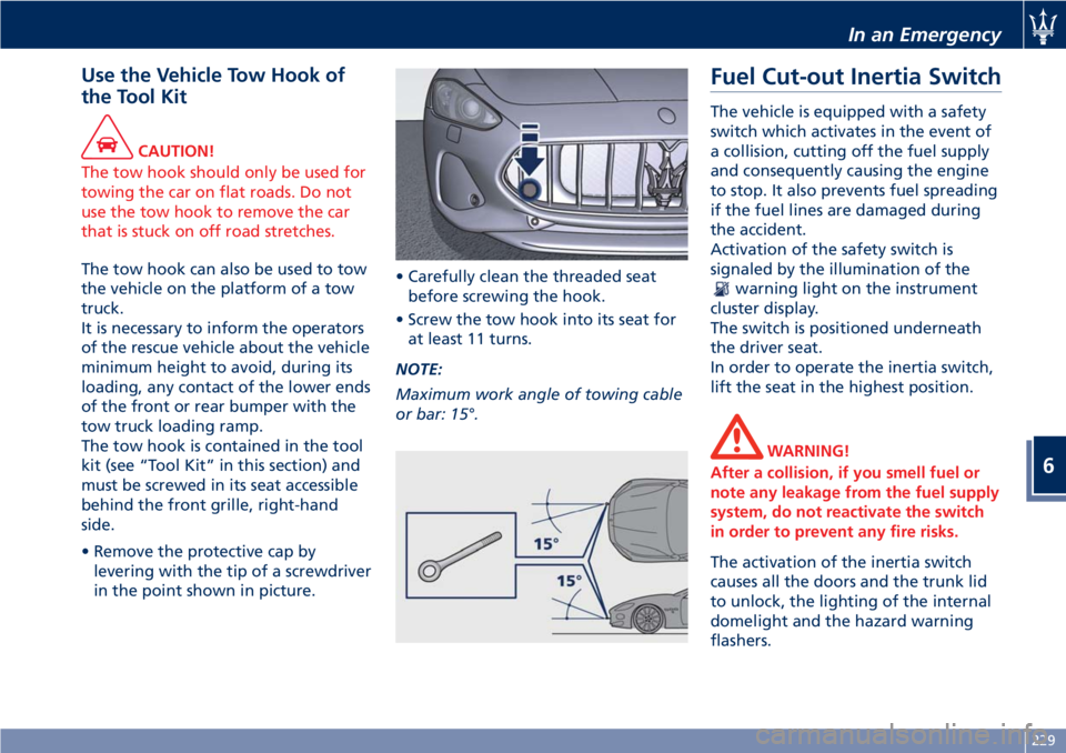
The tow hook is contained in the tool
kit (see “Tool Kit” in this section) and
must be screwed in its seat accessible
behind the front grille, right-hand
side.
• Remove the protective cap by
levering with the tip of a screwdriver
in the point shown in picture.• Carefully clean the threaded seat
before screwing the hook.
• Screw the tow hook into its seat for
at least 11 turns.
NOTE:
Maximum work angle of towing cable
or bar: 15°.
Fuel Cut-out Inertia Switch
The vehicle is equipped with a safety
switch which activates in the event of
a collision, cutting off the fuel supply
and consequently causing the engine
to stop. It also prevents fuel spreading
if the fuel lines are damaged during
the accident.
Activation of the safety switch is
signaled by the illumination of the
warning light on the instrument
cluster display.
The switch is positioned underneath
the driver seat.
In order to operate the inertia switch,
lift the seat in the highest position.
WARNING!
After a collision, if you smell fuel or
note any leakage from the fuel supply
system, do not reactivate the switch
in order to prevent any fire risks.
The activation of the inertia switch
causes all the doors and the trunk lid
to unlock, the lighting of the internal
domelight and the hazard warning
flashers.
In an Emergency
6
229
Page 250 of 296
Always use washer fluid when using
the wipers to remove salt or dirt from
a dry windshield.
Avoid using the wiper blades to
remove frost or ice from the
windshield. Keep the blade rubber out
of contact with petroleum products
such as engine oil, gasoline, etc.
Spray nozzles
If the jet does not work, first check
that there is fluid in the pan (see
paragraph “Level checks” in this
section) then check that the nozzles
are not clogged.
Blades Replacement
• Move the right multifunction lever
into “OFF” position, (see chapter
“Windshield Wipers and Washers” in
section “Understanding the
Vehicle”).
• Lift the end of the arm provided with
the blade from the windshield.
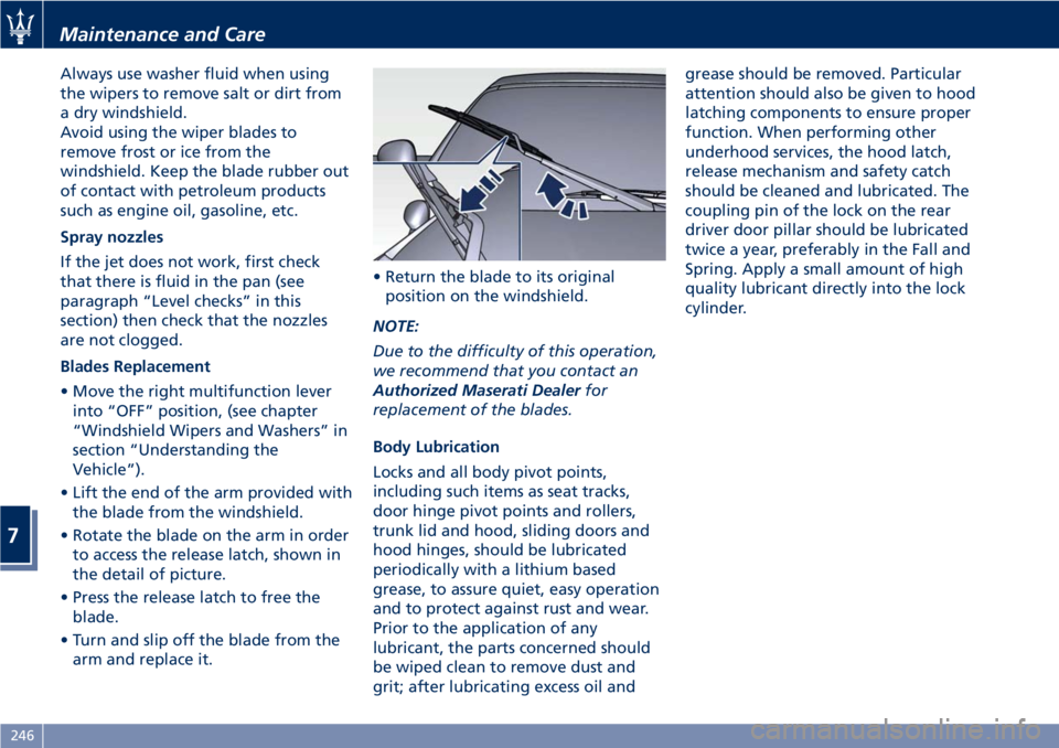
• Rotate the blade on the arm in order
to access the release latch, shown in
the detail of picture.
• Press the release latch to free the
blade.
• Turn and slip off the blade from the
arm and replace it.• Return the blade to its original
position on the windshield.
NOTE:
Due to the difficulty of this operation,
we recommend that you contact an
Authorized Maserati Dealerfor
replacement of the blades.
Body Lubrication
Locks and all body pivot points,
including such items as seat tracks,
door hinge pivot points and rollers,
trunk lid and hood, sliding doors and
hood hinges, should be lubricated
periodically with a lithium based
grease, to assure quiet, easy operation
and to protect against rust and wear.
Prior to the application of any
lubricant, the parts concerned should
be wiped clean to remove dust and
grit; after lubricating excess oil andgrease should be removed. Particular
attention should also be given to hood
latching components to ensure proper
function. When performing other
underhood services, the hood latch,
release mechanism and safety catch
should be cleaned and lubricated. The
coupling pin of the lock on the rear
driver door pillar should be lubricated
twice a year, preferably in the Fall and
Spring. Apply a small amount of high
quality lubricant directly into the lock
cylinder.
Maintenance and Care
7
246
Page 252 of 296
(Continued)
quick coupling from the negative
pole (–) of the battery.
If the battery needs to be removed
from its compartment, you must first
detach the terminal clamp from
negative pole (–) and then the other
terminal clamp from positive pole (+),
after removing the protective cover.
Battery poles are marked positive (+)
and negative (–) and are identified on
the battery case.
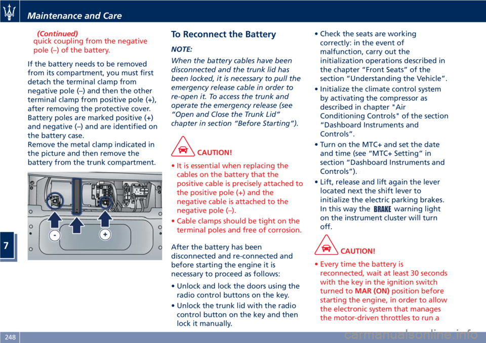
Remove the metal clamp indicated in
the picture and then remove the
battery from the trunk compartment.
To Reconnect the Battery
NOTE:
When the battery cables have been
disconnected and the trunk lid has
been locked, it is necessary to pull the
emergency release cable in order to
re-open it. To access the trunk and
operate the emergency release (see
“Open and Close the Trunk Lid”
chapter in section “Before Starting”).
CAUTION!
• It is essential when replacing the
cables on the battery that the
positive cable is precisely attached to
the positive pole (+) and the
negative cable is attached to the
negative pole (–).
• Cable clamps should be tight on the
terminal poles and free of corrosion.
After the battery has been
disconnected and re-connected and
before starting the engine it is
necessary to proceed as follows:
• Unlock and lock the doors using the
radio control buttons on the key.
• Unlock the trunk lid with the radio
control button on the key and then
lock it manually.• Check the seats are working
correctly: in the event of
malfunction, carry out the
initialization operations described in
the chapter “Front Seats” of the
section “Understanding the Vehicle”.
• Initialize the climate control system
by activating the compressor as
described in chapter "Air
Conditioning Controls" of the section
“Dashboard Instruments and
Controls”.
• Turn on the MTC+ and set the date
and time (see “MTC+ Setting” in
section “Dashboard Instruments and
Controls”).
• Lift, release and lift again the lever
located next the shift lever to
initialize the electric parking brakes.
In this way the
warning light
on the instrument cluster will turn
off.
CAUTION!
• Every time the battery is
reconnected, wait at least 30 seconds
with the key in the ignition switch
turned toMAR (ON)position before
starting the engine, in order to allow
the electronic system that manages
the motor-driven throttles to run a
Maintenance and Care
7
248
Page 259 of 296

Pos. Amp. –
ColorSystem / Component
F39 15 A –
BlueNIM (Inside Roof
Node), NCL (Air
conditioning and
heating system
node), OBD socket,
CSA (Alarm system
siren ECU), CAV
(Motion sensing
alarm ECU), radio,
NAVTRAK
F40 30 A –
GreenHeated rear window
F41 - Not used
F42 7.5 A –
BrownNCL and windshield
wiper control
F43 30 A –
GreenWindshield
wiper/washer
(Connected Devices
Relay INT/A)
F44 20 A –
YellowFront and rear power
outlets (INT/A device
relay) front seat
heating (passenger
side)
F45 - Not used
F46 20 A –
YellowNPG/NPP locksPos. Amp. –
ColorSystem / Component
F47 30 A –
GreenNPG (Driver’s door
node)
F48 30 A –
GreenNPP (Passenger’s
door node)
F49 7.5 A –
BrownNVO (Steering wheel
node), CSG (Power
steering ECU), CSP
(Twilight/rain sensor
ECU), NIM (Inside
Roof Node), NCL,
Radio, CEM, CRP,
domelight molding,
NAVTRAK
F50 7.5 A –
BrownAir bag system
F51 7.5 A –
BrownNCA (Automatic
Gearbox Node)
F52 15 A –
BlueFront seat heating
(driver side) (INT/A
device relay)
F53 10 A –
RedRear fog lights
Fuses in Trunk Compartment
• To access the fuses, remove the floor
panel.• Remove the inside covering panel of
the battery compartment.
There are two control boxes.
• To access the fuses inside the control
boxes, remove the covers by levering
up the fastening tabs.
Maintenance and Care
7
255
Page 262 of 296
Reverse and Rear Fog Light
To replace a bulb of these lights:
• Lift the trunk compartment lid.
• Remove the panel from the trunk lid.
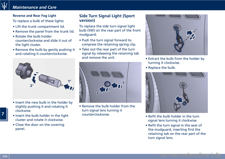
• Rotate the bulb holder
counterclockwise and slide it out of
the light cluster.
• Remove the bulb by gently pushing it
and rotating it counterclockwise.
• Insert the new bulb in the holder by
slightly pushing it and rotating it
clockwise.
• Insert the bulb holder in the light
cluster and rotate it clockwise.
• Close the door on the covering
panel.Side Turn Signal Light (Sport
version)
To replace the side turn signal light
bulb (5W) on the rear part of the front
mudguard:
• Push the turn signal forward to
compress the retaining spring clip.
• Take out the rear part of the turn
signal by releasing the retaining tab
and remove the unit.
• Remove the bulb holder from the
turn signal lens turning it
counterclockwise.• Extract the bulb from the holder by
turning it clockwise.
• Replace the bulb.
• Refit the bulb holder in the turn
signal lens turning it clockwise.
• Refit the turn signal in the seat of
the mudguard, inserting first the
retaining tab on the rear part of the
turn signal lens.
Maintenance and Care
7
258