2020 MASERATI GRANTURISMO CONVERTIBLE fuse
[x] Cancel search: fusePage 36 of 296

Opening from the Inside
To open the door, even if the lock is
engaged, pull the internal handle.
There are two buttons in front of the
transmission lever which operate the
door locking and unlocking functions:
: door locking;
: door unlocking.NOTE:
By pulling the internal handle on the
driver’s door, all the locks can be
released at the same time or just the
driver’s door, depending on the MTC+
settings (see "MTC+ Settings" in
section "Dashboard Instrument and
Controls").
Door Open Warning Lights
If the doors and the engine/luggage
compartment lids are not closed
properly, this is signaled by the
illumination of relative symbols on the
instrument panel display, accompanied
by the messages “Door open” or
“Doors open” shown in the picture.
Door Lock ECU Initialization
Every time the battery is connected or
a fuse replaced, you must perform the
system initialization procedure toensure proper system operation. To
perform this procedure, lock and then
unlock the doors using the buttons
andon the radio control device.
For more details, see "Maintenance-
Free Battery" in section "Maintenance
and Care".
Door Open Indicator Light
Each door is provided with a reflector
fitted on the rear side of the door
panel that makes it visible when
illuminated by the headlights of a
vehicle.
Signal
Upon exceeding a speed of 3 mph
(5 km/h), if one or more doors/lid are
open or not properly closed, a warning
signal will be activated.
Door Courtesy Light
Each door panel is fitted with a
courtesy light, on the lower part of the
door framework, to illuminate the
area where passengers enter/exit the
vehicle.
Before Starting
2
32
Page 78 of 296
Front Seats
Seats and seat belts are part of the
Occupant Restraint System of the
vehicle. For further information, see
chapter “Occupant Restraint System”
in Section “Before Starting”.
WARNING!
Be sure everyone in your vehicle is in a
seat and using a seat belt properly.
Seat Adjustments
The seats can only be adjusted with
the key in the ignition switch inMAR
(ON)position.
It is however possible, when the door
is closed, to operate the seat for
approx. 15 seconds after turning the
key toSTOP (OFF)position and then
for other 15 seconds after the last
operation.
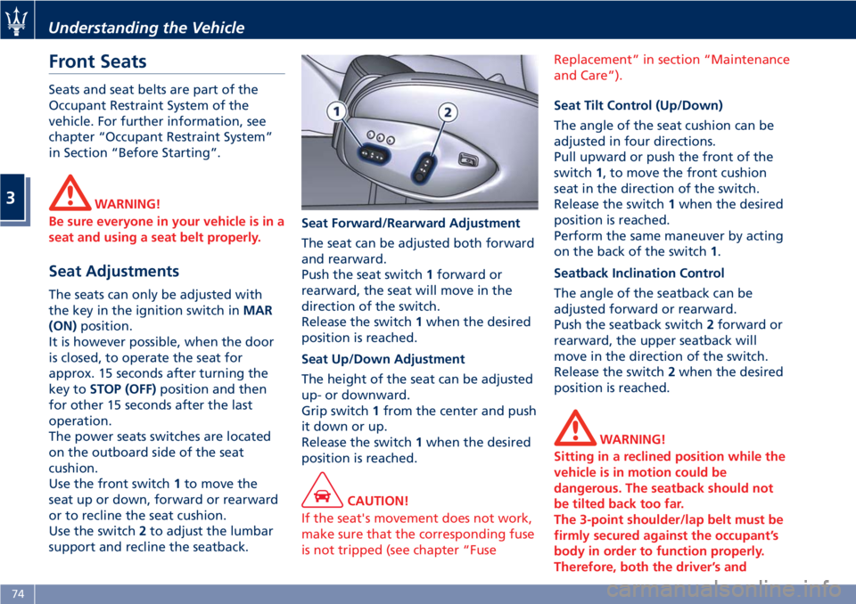
The power seats switches are located
on the outboard side of the seat
cushion.
Use the front switch1to move the
seat up or down, forward or rearward
or to recline the seat cushion.
Use the switch2to adjust the lumbar
support and recline the seatback.Seat Forward/Rearward Adjustment
The seat can be adjusted both forward
and rearward.
Push the seat switch1forward or
rearward, the seat will move in the
direction of the switch.
Release the switch1when the desired
position is reached.
Seat Up/Down Adjustment
The height of the seat can be adjusted
up- or downward.
Grip switch1from the center and push
it down or up.
Release the switch1when the desired
position is reached.
CAUTION!
If the seat's movement does not work,
make sure that the corresponding fuse
is not tripped (see chapter “FuseReplacement” in section “Maintenance
and Care”).
Seat Tilt Control (Up/Down)
The angle of the seat cushion can be
adjusted in four directions.
Pull upward or push the front of the
switch1, to move the front cushion
seat in the direction of the switch.
Release the switch1when the desired
position is reached.
Perform the same maneuver by acting
on the back of the switch1.
Seatback Inclination Control
The angle of the seatback can be
adjusted forward or rearward.
Push the seatback switch2forward or
rearward, the upper seatback will
move in the direction of the switch.
Release the switch2when the desired
position is reached.
WARNING!
Sitting in a reclined position while the
vehicle is in motion could be
dangerous. The seatback should not
be tilted back too far.
The 3-point shoulder/lap belt must be
firmly secured against the occupant’s
body in order to function properly.
Therefore, both the driver’s and
Understanding the Vehicle
3
74
Page 106 of 296
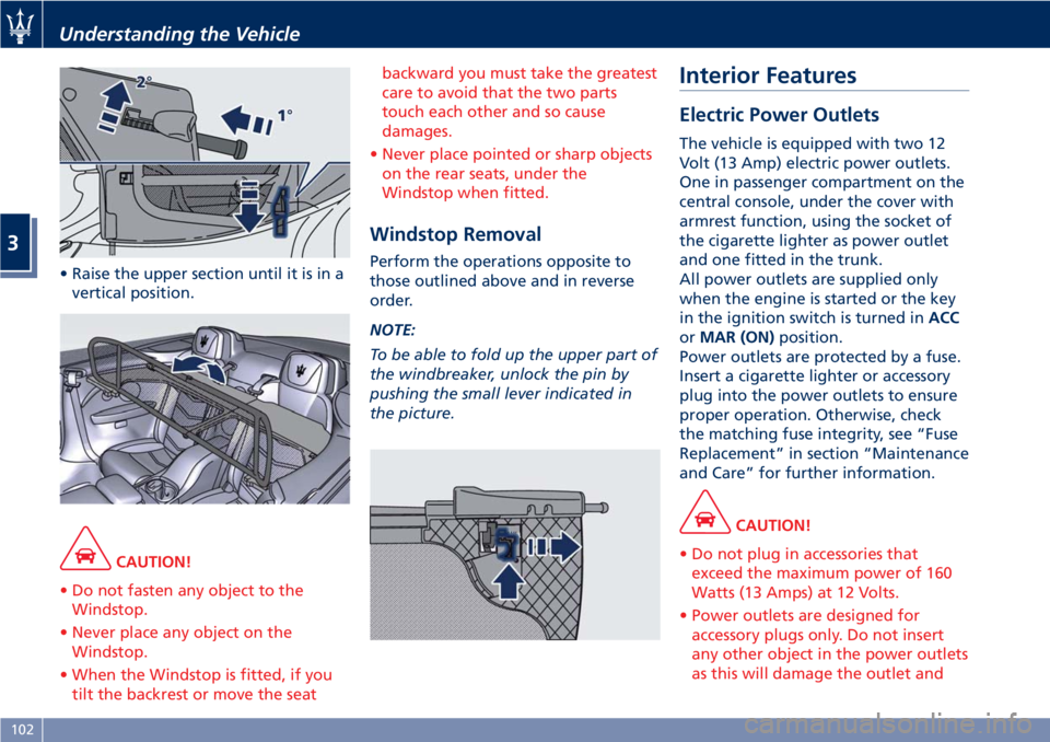
• Raise the upper section until it is in a
vertical position.
CAUTION!
• Do not fasten any object to the
Windstop.
• Never place any object on the
Windstop.
• When the Windstop is fitted, if you
tilt the backrest or move the seatbackward you must take the greatest
care to avoid that the two parts
touch each other and so cause
damages.
• Never place pointed or sharp objects
on the rear seats, under the
Windstop when fitted.
Windstop Removal
Perform the operations opposite to
those outlined above and in reverse
order.
NOTE:
To be able to fold up the upper part of
the windbreaker, unlock the pin by
pushing the small lever indicated in
the picture.
Interior Features
Electric Power Outlets
The vehicle is equipped with two 12
Volt (13 Amp) electric power outlets.
One in passenger compartment on the
central console, under the cover with
armrest function, using the socket of
the cigarette lighter as power outlet
and one fitted in the trunk.
All power outlets are supplied only
when the engine is started or the key
in the ignition switch is turned inACC
orMAR (ON)position.
Power outlets are protected by a fuse.
Insert a cigarette lighter or accessory
plug into the power outlets to ensure
proper operation. Otherwise, check
the matching fuse integrity, see “Fuse
Replacement” in section “Maintenance
and Care” for further information.
CAUTION!
• Do not plug in accessories that
exceed the maximum power of 160
Watts (13 Amps) at 12 Volts.
• Power outlets are designed for
accessory plugs only. Do not insert
any other object in the power outlets
as this will damage the outlet and
Understanding the Vehicle
3
102
Page 107 of 296
blow the fuse. Damages caused by
improper use of the power outlet
are not covered by the New Vehicle
Limited Warranty.
WARNING!
To avoid serious injury or death:
•Only devices designed for use in this
type of outlet should be inserted
into any 12 Volt outlet.
•Replacing the fuses that protect
power outlets with others of higher
amperage, there is the risk of fire.
•Do not touch with wet hands.
•If this outlet is mishandled, it may
cause an electric shock and failure.
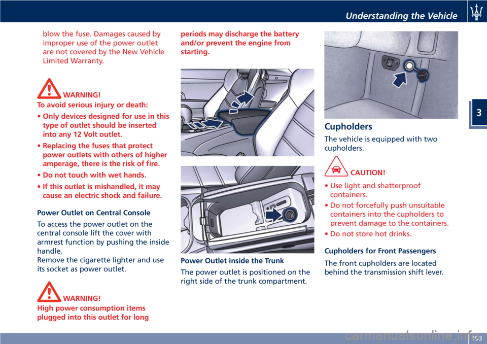
Power Outlet on Central Console
To access the power outlet on the
central console lift the cover with
armrest function by pushing the inside
handle.
Remove the cigarette lighter and use
its socket as power outlet.
WARNING!
High power consumption items
plugged into this outlet for longperiods may discharge the battery
and/or prevent the engine from
starting.
Power Outlet inside the Trunk
The power outlet is positioned on the
right side of the trunk compartment.
Cupholders
The vehicle is equipped with two
cupholders.
CAUTION!
• Use light and shatterproof
containers.
• Do not forcefully push unsuitable
containers into the cupholders to
prevent damage to the containers.
• Do not store hot drinks.
Cupholders for Front Passengers
The front cupholders are located
behind the transmission shift lever.
Understanding the Vehicle
3
103
Page 177 of 296
When the system refuses to engage a
gear, an acoustic signal will sound for
a few seconds.
Sequential manual operation can only
be selected from the D (Drive) position
whatever the function (SPORT,
NORMAL) active at the time of the
request. The gear selected by the
automatic transmission will remain
engaged when the transmission shift
lever is moved.
Shifting the lever back to D (Drive),
automatic operation will instantly be
resumed, and a gear will be engaged
based on the driving style and mode
selected.
In the event of a failure of the
sequential manual gearshift system,
the transmission ECU will select
automatic operation.
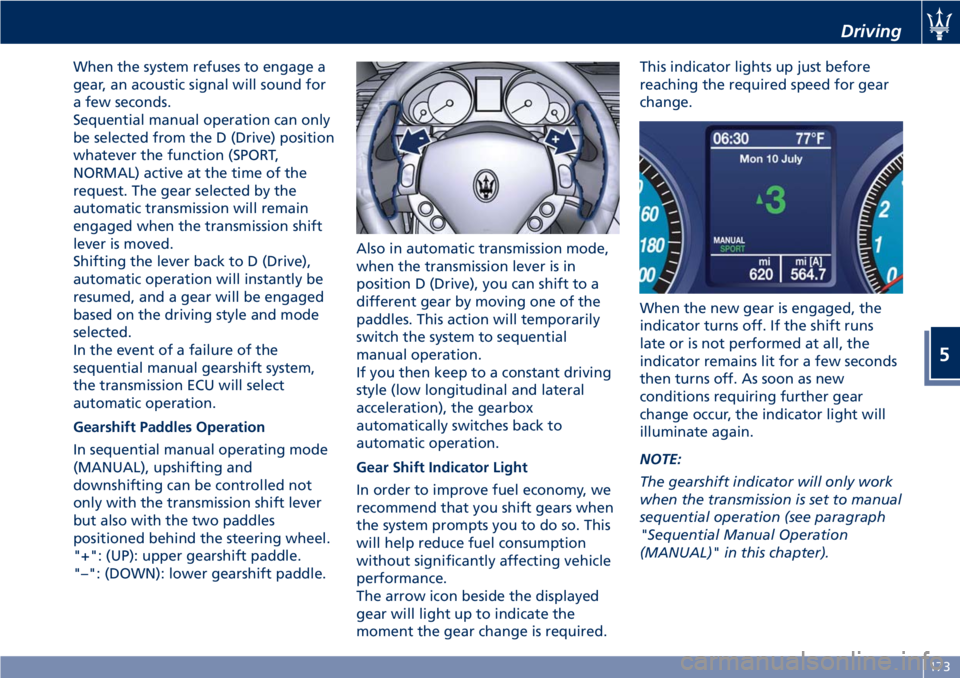
Gearshift Paddles Operation
In sequential manual operating mode
(MANUAL), upshifting and
downshifting can be controlled not
only with the transmission shift lever
but also with the two paddles
positioned behind the steering wheel.
"+": (UP): upper gearshift paddle.
"–": (DOWN): lower gearshift paddle.Also in automatic transmission mode,
when the transmission lever is in
position D (Drive), you can shift to a
different gear by moving one of the
paddles. This action will temporarily
switch the system to sequential
manual operation.
If you then keep to a constant driving
style (low longitudinal and lateral
acceleration), the gearbox
automatically switches back to
automatic operation.
Gear Shift Indicator Light
In order to improve fuel economy, we
recommend that you shift gears when
the system prompts you to do so. This
will help reduce fuel consumption
without significantly affecting vehicle
performance.
The arrow icon beside the displayed
gear will light up to indicate the
moment the gear change is required.This indicator lights up just before
reaching the required speed for gear
change.
When the new gear is engaged, the
indicator turns off. If the shift runs
late or is not performed at all, the
indicator remains lit for a few seconds
then turns off. As soon as new
conditions requiring further gear
change occur, the indicator light will
illuminate again.
NOTE:
The gearshift indicator will only work
when the transmission is set to manual
sequential operation (see paragraph
"Sequential Manual Operation
(MANUAL)" in this chapter).
Driving
5
173
Page 191 of 296
• by turning the engine off; or
• by turning ON/OFF switch to "OFF"
position.
Warnings while Driving with CC
WARNING!
•When driving with CC activated, do
not shift to N (Neutral) position. It is
advisable to activate CC only when
traffic and road conditions permit
safe use of this device, that is: on
straight and dry roads, expressways
or highways, smooth flowing traffic
and smooth asphalt. Do not activate
this device when driving in town or
in heavy traffic.
•CC can only be activated at speeds
exceeding 19 mph (30 km/h).
•CC can only be activated in 4th, 5th
or 6th gear, depending upon the
vehicle speed.
•When driving downhill with the CC
activated, the vehicle may pick up
speed slightly exceeding the speed
stored, due to the change in the
engine load.
•In the event of malfunctioning or
failure of CC, turn ON/OFF switch to
"OFF" position and contact the
Authorized Maserati Dealer afterhaving checked that the relative
fuse is in proper working order.
•ON/OFF switch can be always left at
"ON" position without damaging
the CC. In any case, it is advisable to
deactivate the CC when it is not in
use. Turn ON/OFF switch to "OFF"
position to prevent any speeds from
being unintentionally stored.
Tires - General
Information
Tire Safety Information
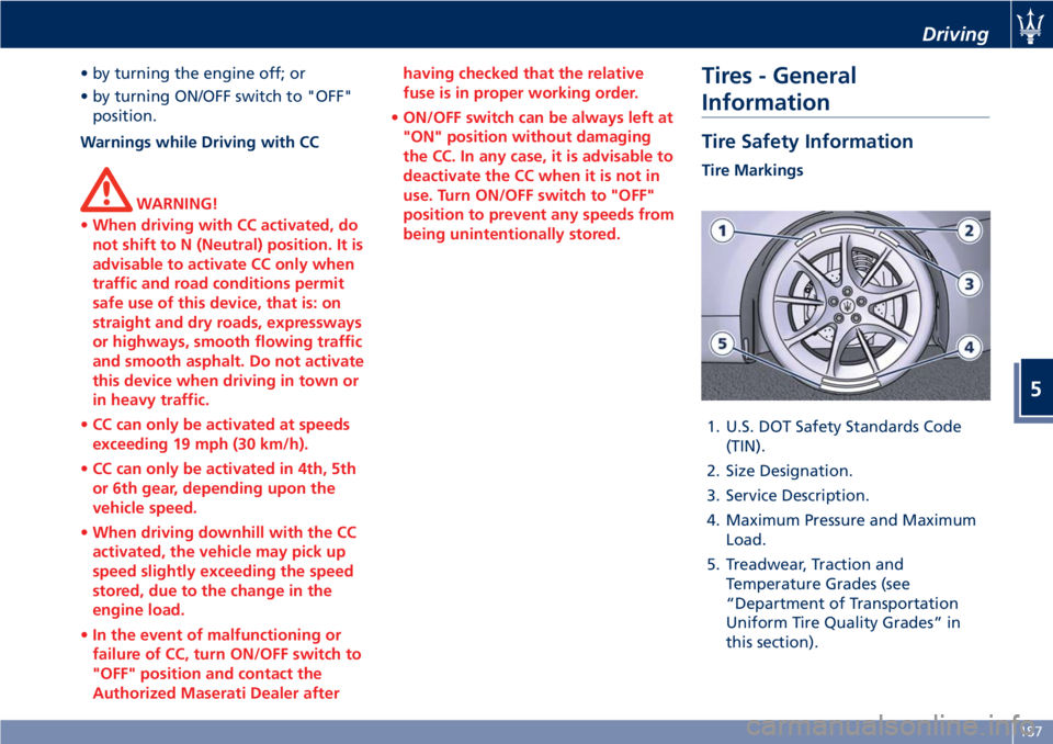
Tire Markings
1. U.S. DOT Safety Standards Code
(TIN).
2. Size Designation.
3. Service Description.
4. Maximum Pressure and Maximum
Load.
5. Treadwear, Traction and
Temperature Grades (see
“Department of Transportation
Uniform Tire Quality Grades” in
this section).
Driving
5
187
Page 235 of 296

7 – Maintenance and Care
Scheduled Maintenance Service............................ 232
Scheduled Service Plan................................... 234
Maintenance Procedures................................. 239
Maintenance-Free Battery................................ 247
Fuse Replacement...................................... 251
Bulb Replacement...................................... 257
A/C System Maintenance................................. 262
Wheels Maintenance.................................... 263
Bodywork Maintenance and Care.......................... 265
Interior Maintenance and Care............................ 268
Vehicle Stored for Long Periods............................ 269
Restarting the Vehicle.................................... 269
Battery Statement...................................... 270
231
Page 255 of 296

Fuse Replacement
Used Fuses Characteristics
When an electrical device is not
functioning, check that the
corresponding fuse is in proper
working order (intact).
AFuse intact
BFuse blown
Replace the faulty fuse with a new
one featuring the same rating, by
using appropriate forceps.The color identifies the value of the
fuses in amperes which is also
reported on them.
The vehicle is endowed with mini- and
maxi-fuses.
The table shows the match between
color and amperage of mini and maxi
fuses.
Type
Mini Fuse Maxi Fuse
Beige - 5 Yellow - 20
Brown - 7.5 Green - 30
Red - 10 Orange - 40
Blue-15 Red-50
Yellow - 20 Blue - 60
White - 25
Green - 30
CAUTION!
• Never replace a blown fuse with
anything other than a new and
suitable fuse (same rating).
• After replacing a fuse, if the fault
recurs, contact anAuthorized
Maserati Dealer.
Position of Fuses
The fuses are located in three parts of
the vehicle, namely:
• On the right hand side of the engine
compartment.
• Behind the glove compartment, to
the left of the steering wheel.
• In the trunk compartment next to
the battery.
Fuses Inside Engine
Compartment
• To access the fuses, lift the hood and
remove the covering panel.
Maintenance and Care
7
251