Page 439 of 557

6-19
What to do in an emergency
6If any of the equipment such as the
jack, lug nuts, studs, or other equip-
ment is damaged or in poor condi-
tion, do not attempt to change the
tire and call for assistance.
Use of compact spare tires
Compact spare tires are designed for
emergency use only. Drive carefully
on the compact spare tire and
always follow the safety precautions.When driving with the compact spare
tire mounted to your vehicle:
Check the tire pressure after
installing the compact spare tire.
The compact spare tire should be
inflated to 60 psi (420 kPa). Do not take this vehicle through an
automatic car wash while the com-
pact spare tire is installed.
Do not use the compact spare tire on any other vehicle because this
tire has been designed especially
for your vehicle.
The compact spare tire’s tread life is shorter than a regular tire. Inspect
your compact spare tire regularly
and replace worn compact spare
tires with the same size and design,
mounted on the same wheel.
Do not use more than one com- pact spare tire at a time.
Do not tow a trailer while the com- pact spare tire is installed.
When the original tire and wheel
are repaired and reinstalled on the
vehicle, the lug nut torque must be
set correctly. The correct lug nut
tightening torque is 79~94 lbf·ft
(11~13 kgf·m).
NOTICE
Your vehicle has metric threads
on the studs and lug nuts. Make
certain during tire changing that
the same nuts that were
removed are reinstalled. If you
have to replace your lug nuts
make sure they have metric
threads to avoid damaging the
studs and ensure the wheel is
properly secured to the hub.
Consult an authorized HYUNDAI
dealer for assistance.
CAUTION
To prevent compact spare tire
failure and loss of control pos-
sibly resulting in an accident:
Use the compact spare tire
only in an emergency.
NEVER operate your vehicle
over 50 mph (80 km/h).
Do not exceed the vehicle's
maximum load rating or the
load carrying capacity shown
on the sidewall of the com-
pact spare tire.
Do not use the compact spare
tire continuously. Repair or
replace the original tire as
soon as possible to avoid fail-
ure of the compact spare tire.
WARNING
Page 460 of 557

E
EX
X P
PL
LA
A N
N A
AT
TI
IO
O N
N
O
O F
F
S
S C
C H
H E
ED
D U
U L
LE
E D
D
M
M A
AI
IN
N T
TE
EN
N A
AN
N C
CE
E
I
IT
T E
EM
M S
S
Engine Oil and Filter
The engine oil and filter should be
changed at the intervals specified in
the maintenance schedule. If the
vehicle is being driven in severe con-
ditions, more frequent oil and filter
changes are required.
Drive Belts
Inspect all drive belts for evidence of
cuts, cracks, excessive wear or oil
saturation and replace if necessary.
Drive belts should be checked peri-
odically for proper tension and
adjusted as necessary.
Fuel Filter
A clogged-up fuel filter may limit the
vehicle driving speed, damage the
emission system, and cause the
hard starting. When a considerable
amount of foreign substances are
accumulated in the fuel tank, the fuel
filter should be replaced.
Upon installing a new fuel filter, oper-
ate the engine for several minutes,
and check the connections for any
leakages. Fuel filters should be
installed by an authorized HYUNDAI
dealer.
Fuel Lines, Fuel Hoses and
Connections
Check the fuel lines, fuel hoses and
connections for leakage and dam-
age. Have an authorized HYUNDAI
dealer replace any damaged or leak-
ing parts immediately.
Vapor Hose and Fuel Filler
Cap
The vapor hose and fuel filler cap
should be inspected at those inter-
vals specified in the maintenance
schedule. Make sure a new vapor
hose or fuel filler cap is correctly
replaced.
Vacuum Crankcase Ventilation
Hoses (if equipped)
Inspect the surface of hoses for evi-
dence of heat and/or mechanical
damage. Hard and brittle rubber,
cracking, tears, cuts, abrasions, and
excessive swelling indicate deterio-
ration. Particular attention should be
paid to examine those hose surfaces
nearest to high heat sources, such
as the exhaust manifold.
Inspect the hose routing to ensure
that the hoses do not come in con-
tact with any heat source, sharp
edges or moving component which
might cause heat damage or
mechanical wear. Inspect all hose
connections, such as clamps and
couplings, to make sure they are
secure, and that no leaks are pres-
ent. Hoses should be replaced
immediately if there is any evidence
of deterioration or damage.
Maintenance
7-18
Page 476 of 557

When you do not use the vehiclefor a long time in a low tempera-
ture area, disconnect the battery
and keep it indoors.
Always charge the battery fully to prevent battery case damage
in low temperature areas.
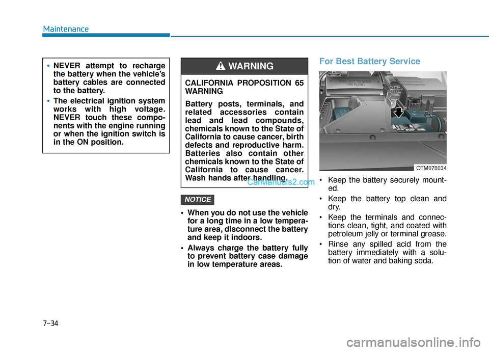
For Best Battery Service
Keep the battery securely mount- ed.
Keep the battery top clean and dry.
Keep the terminals and connec- tions clean, tight, and coated with
petroleum jelly or terminal grease.
Rinse any spilled acid from the battery immediately with a solu-
tion of water and baking soda.
NOTICE
NEVER attempt to recharge
the battery when the vehicle’s
battery cables are connected
to the battery.
The electrical ignition system
works with high voltage.
NEVER touch these compo-
nents with the engine running
or when the ignition switch is
in the ON position.
CALIFORNIA PROPOSITION 65
WARNING
Battery posts, terminals, and
related accessories contain
lead and lead compounds,
chemicals known to the State of
California to cause cancer, birth
defects and reproductive harm.
Batteries also contain other
chemicals known to the State of
California to cause cancer.
Wash hands after handling.
WARNING
OTM078034
Maintenance
7-34
Page 496 of 557

7-54
Maintenance
Engine Compartment Panel
Fuse Replacement
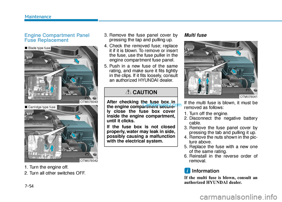
1. Turn the engine off.
2. Turn all other switches OFF.3. Remove the fuse panel cover by
pressing the tap and pulling up.
4. Check the removed fuse; replace it if it is blown. To remove or insert
the fuse, use the fuse puller in the
engine compartment fuse panel.
5. Push in a new fuse of the same rating, and make sure it fits tightly
in the clips. If it fits loosely, consult
an authorized HYUNDAI dealer.
Multi fuse
If the multi fuse is blown, it must be
removed as follows:
1. Turn off the engine.
2. Disconnect the negative batterycable.
3. Remove the fuse panel cover by pressing the tab and pulling it up.
4. Remove the nuts shown in the pic- ture above.
5. Replace the fuse with a new one of the same rating.
6. Reinstall in the reverse order of removal.
Information
If the multi fuse is blown, consult an
authorized HYUNDAI dealer.
i
OTM078041
After checking the fuse box in
the engine compartment secure-
ly close the fuse box cover
inside the engine compartment,
until it clicks.
If the fuse box is not closed
properly, water may leak in side,
possibly causing a malfunction
with the electrical system.
CAUTION
OTM078043
OTM078042
■Blade type fuse
■Cartridge type fuse
Page 503 of 557
Engine compartment fuse panel
Fuse NameFuse RatingProtected Component
FUSE
INVERTER30AAC Inverter Unit
POWER TAILGATE30APower Tail Gate Module
TRAILER 330ATrailer Lamp
IG240AStart Relay, ICU Junction Block (Fuse - A/C, WASHER, WIPER (REAR), MODULE 1,
MODULE 2, REAR A/C)
OIL PUMP40AElectronic Oil Pump Module
COOLING FAN 250ACooling Fan Relay
HEATED MIRROR10ADriver/Passenger Power Outside Mirror, A/C Control Module
A/C 210AA/C Control Module
WIPER FRT 210AWiper (LO) Relay, Front Wiper Motor
ECU 415APCM
AMS10ABattery Sensor
VACUUM PUMP20AVacuum Pump
4WD20AAWD ECM
Maintenance
7
7-61
Page 504 of 557
Engine compartment fuse panel
Fuse NameFuse RatingProtected Component
PCB Block
SENSOR 615AElectronic Oil Pump Module, [2.0 T-GDI] Vacuum Pump
ABS 310AESC Module
SENSOR 710ASmart Cruise Control Radar
SENSOR 510ACanister Close Valve, E/R Junction Block (Cooling Fan Relay)
IGN COIL20AIgnition Coil #1/#2/#3/#4
SENSOR 110A
[2.4 GDI] Fuel Pump Relay, Variable Intake Solenoid Valve, Purge Control Solenoid
Valve, Oil Control Valve
[2.0 T-GDI] Fuel Pump Relay, RCV Control Solenoid Valve, Purge Control Solenoid
Valve, Oil Control Valve
E-CVVT 220APCM
A/C 110A[2.4 GDI] A/CON Relay
WIPER FRT 125AWiper Main Relay
TCU 210ATransmission Range Switch
ECU 310APCM
B/ALARM HORN15ABurglar Alarm Horn Relay, Horn Relay
Maintenance
7-62
Page 505 of 557
Engine compartment fuse panel
Fuse NameFuse RatingProtected Component
PCB Block
HORN15AHorn Relay
FUEL PUMP20AFuel Pump Relay
ECU 120APCM
SENSOR 210A[2.4 GDI] A/C Comp Relay, Oxygen Sensor (Up/Down)
[2.0 T-GDI] Oxygen Sensor (Up/Down)
E-CVVT 120APCM
POWER OUTLET 120AFront Power Outlet
POWER OUTLET 220ARear Power Outlet
ACC10AICU Junction Block (Fuse - ACC)
TCU 115APCM
IG 140APDM (IG1) Relay
Maintenance
7-63
7
Page 506 of 557
Engine compartment fuse panel(Battery terminal cover)
Inside the fuse/relay box cover, you
can find the fuse/relay label describ-
ing fuse/relay names and ratings.
Information
Not all fuse panel descriptions in this
manual may be applicable to your
vehicle; the information is accurate at
the time of printing. When you inspect
the fuse panel in your vehicle, refer to
the fuse panel label.
i
OTMA078046
OTM078047
After checking the fuse panel in the engine compartment, securely
install the cover. If it is not securely latched, electrical failure may occur
from water contact.
NOTICE
Maintenance
7-64