Page 585 of 613
7-67
7
Maintenance
(1) Tail/Stop lamp
(2) Turn signal lamp
(3) Tail lamp
(4) Backup lamp
(5) Stop lamp
Tail/Stop lamp and turn signal lamp
1. Turn off the engine.
2. Open the tailgate.
3. Open the lamp assembly retaining
screw covers.
4. Loosen the lamp assembly retain-
ing screws with a cross-tip screw-
driver.5. Remove the rear combination
lamp assembly from the body of
the vehicle.
OAE076037OAE076038
Page 586 of 613
7-68
Maintenance
6. Remove the socket from the
assembly by turning the socket
counterclockwise until the tabs on
the socket align with the slots on
the assembly.7. Remove the bulb from the socket
by pressing it in and rotating it
counterclockwise until the tabs on
the bulb align with the slots in the
socket. Pull the bulb out of the
socket.
8. Insert a new bulb by inserting it
into the socket and rotating it until
it locks into place.
9. Install the socket into the assem-
bly by aligning the tabs on the
socket with the slots in the assem-
bly. Push the socket into the
assembly and turn the socket
clockwise.
10. Reinstall the lamp assembly to
the body of the vehicle.
Tail lamp and backup lamp
1. Turn off the engine.
2. Open the tailgate.
3. Remove the service cover using a
flat-blade screwdriver.
OAE076039
OAEPH078031
■Type A
■Type B
Tail/Stop lamp
Turn signal lamp
Turn signal lamp
OAE076041
Page 591 of 613
7-73
7
Maintenance
Do not use strong soap, chemi-
cal detergents or hot water, and
do not wash the vehicle in direct
sunlight or when the body of the
vehicle is warm.
Be careful when washing the
side windows of your vehicle.
Especially, with high-pressure
water, water may leak through
the windows and wet the interior.
To prevent damage to the plastic
parts, do not clean with chemi-
cal solvents or strong deter-
gents.
To prevent damage to the charg-
ing door, make sure to close and
lock the vehicle doors when
washing (high-pressure wash-
ing, automatic car washing, etc.)
the vehicle.
High-pressure washing
When using high-pressure washers,
make sure to maintain sufficient dis-
tance from the vehicle.
Insufficient clearance or excessive
pressure can lead to component
damage or water penetration.
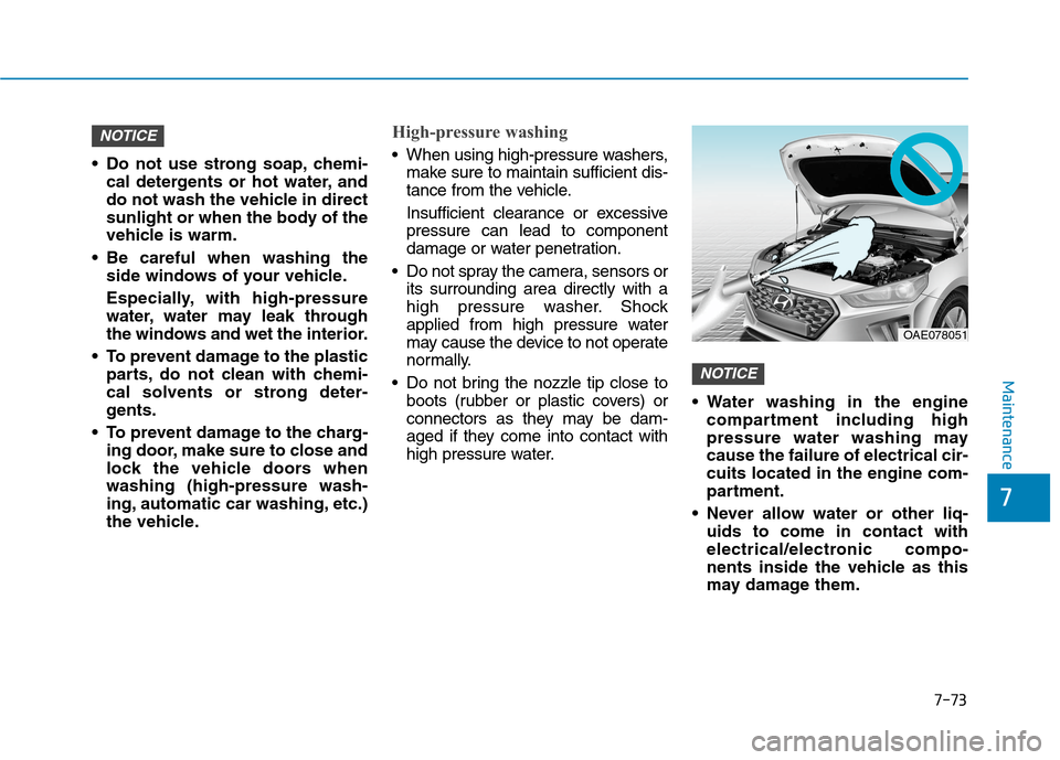
Do not spray the camera, sensors or
its surrounding area directly with a
high pressure washer. Shock
applied from high pressure water
may cause the device to not operate
normally.
Do not bring the nozzle tip close to
boots (rubber or plastic covers) or
connectors as they may be dam-
aged if they come into contact with
high pressure water. Water washing in the engine
compartment including high
pressure water washing may
cause the failure of electrical cir-
cuits located in the engine com-
partment.
Never allow water or other liq-
uids to come in contact with
electrical/electronic compo-
nents inside the vehicle as this
may damage them.
NOTICE
NOTICE
OAE078051
Page 600 of 613
7-82
Maintenance
Canister
Fuel vapours generated inside the
fuel tank are absorbed and stored in
the onboard canister. When the
engine is running, the fuel vapours
absorbed in the canister are drawn
into the surge tank through the purge
control solenoid valve.
Purge Control Solenoid Valve
(PCSV)
The purge control solenoid valve is
controlled by the Engine Control
Module (ECM); when the engine
coolant temperature is low during
idling, the PCSV closes so that evap-
orated fuel is not taken into the
engine. After the engine warms-up
during ordinary driving, the PCSV
opens to introduce evaporated fuel to
the engine.
3. Exhaust emission control
system
The Exhaust Emission Control
System is a highly effective system
which controls exhaust emissions
whilst maintaining good vehicle per-
formance.
When the engine starts or fails to
start, excessive attempts to restart
the engine may cause damage to the
emission system.
Engine exhaust (carbon monox-
ide) precautions
Carbon monoxide can be present
with other exhaust fumes. If you
smell exhaust fumes of any kind in
your vehicle, drive with all the win-
dows fully open. Have your vehicle
checked and repaired immediately.
Engine exhaust gases contain
carbon monoxide (CO). Though
colourless and odourless, it is
dangerous and could be lethal if
inhaled. Follow the instructions
on this page to avoid CO poi-
soning.
WARNING
Page 601 of 613
7-83
7
Maintenance
Do not operate the engine in con-
fined or closed areas (such as
garages) any more than what is
necessary to move the vehicle in or
out of the area.
When the vehicle is stopped in an
open area for more than a short
time with the engine running,
adjust the ventilation system (as
needed) to draw outside air into the
vehicle.
Never sit in a parked or stopped
vehicle for any extended time with
the engine running.
When the engine stalls or fails to
start, excessive attempts to restart
the engine may cause damage to
the emission control system.Operating precautions for cat-
alytic converters (if equipped)Your vehicle is equipped with a cat-
alytic converter emission control
device. To prevent damage to the
catalytic converter and to your vehi-
cle, take the following precautions:
Use only UNLEADED FUEL for
petrol engines.
Do not operate the vehicle when
there are signs of engine malfunc-
tion, such as misfire or a noticeable
loss of performance.
Do not misuse or abuse the
engine. Examples of misuse are
coasting with the hybrid system off
and descending steep grades in
gear with the hybrid system off.
Do not operate the engine at high
idle speed for extended periods (5
minutes or more). The exhaust system and cat-
alytic converter are very hot
during and immediately after
the engine has been running. To
avoid SERIOUS INJURY or
DEATH:
Do not park, idle, or drive the
vehicle over or near flamma-
ble objects, such as grass,
vegetation, paper, leaves, etc.
A hot exhaust system can
ignite flammable items under
your vehicle.
Keep away from the exhaust
system and catalytic convert-
er or you may get burned.
Also, Do not remove the heat
sink around the exhaust sys-
tem, do not seal the bottom of
the vehicle, and do not coat
the vehicle for corrosion con-
trol. It may present a fire risk
under certain conditions.
WARNING
Page 602 of 613
7-84
Maintenance
Do not modify or tamper with any
part of the engine or emission con-
trol system. All inspections and
adjustments must be made by an
authorised HYUNDAI dealer.
Avoid driving with an extremely low
fuel level.
Running out of fuel could cause
the engine to misfire, damaging
the catalytic converter.
Page 603 of 613
7-85
7
Maintenance
P PR
RO
OC
CE
ED
DU
UR
RE
E
F
FO
OR
R
E
EN
NT
TE
ER
RI
IN
NG
G
F
FO
OR
RC
CE
ED
D
E
EN
NG
GI
IN
NE
E
A
AC
CT
TI
IV
VA
AT
TI
IO
ON
N
M
MO
OD
DE
E
If the engine needs to be kept run-
ning whilst the vehicle is stopped to
inspect emission gas or perform
vehicle maintenance, follow below
procedure to enter forced engine
activation mode.
1. Place the shift lever in P (Park)
position with the vehicle stopped.
Engage the parking brake. Then,
follow the steps (1) to (5).
Information
Below steps from (1) to (5) must be
completed within 60 sec. If not, the
process is reset and you must start
again from step (1).(1) Turn the ignition switch to the ON
position. Vehicles equipped with
the smart key, press the Engine
Start/Stop button twice without
depressing the brake pedal.
(2) Place the shift lever in P (Park)
position and depress the acceler-
ator pedal twice.
(3) Place the shift lever in N (Neutral)
position and depress the acceler-
ator pedal twice.
(4) Place the shift lever in P (Park)
position and depress the acceler-
ator pedal twice.
(5) With the brake pedal depressed,
start the engine, and maintain
idling state.
Information
The engine remains in idle state and
the forced engine activation mode is
maintained even when the gear is
shifted to a different position.2. " " indicator on the instrument
cluster blinks when the vehicle is
in forced engine activation mode.
Check the " " indicator blinking
to ensure that the forced engine
activation mode is correctly
entered.
Information
The " " indicator continues blink-
ing until the forced engine activation
mode is cancelled. When the mode is
cancelled the " " indicator will
stop blinking.
3. To cancel the forced engine acti-
vation mode, turn the vehicle off.
i
i
i
Page 604 of 613
8
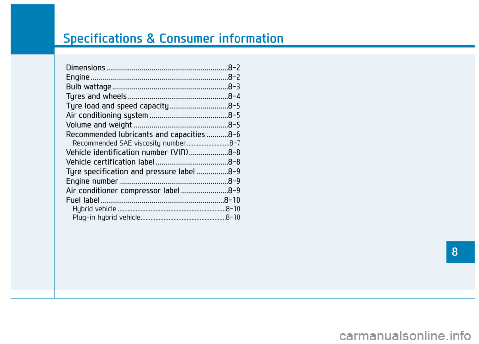
Specifications & Consumer information
8
Specifications & Consumer information
8
Dimensions ..............................................................8-2
Engine ......................................................................8-2
Bulb wattage ...........................................................8-3
Tyres and wheels ...................................................8-4
Tyre load and speed capacity ..............................8-5
Air conditioning system ........................................8-5
Volume and weight ................................................8-5
Recommended lubricants and capacities ...........8-6
Recommended SAE viscosity number ..........................8-7
Vehicle identification number (VIN) ....................8-8
Vehicle certification label .....................................8-8
Tyre specification and pressure label ................8-9
Engine number .......................................................8-9
Air conditioner compressor label ........................8-9
Fuel label ...............................................................8-10
Hybrid vehicle ..................................................................8-10
Plug-in hybrid vehicle....................................................8-10