Page 19 of 613
H19
7. Hold the charging connector han-
dle and connect it to the vehicle
normal charging inlet. Push the
connector until you hear a "click-
ing" sound. If the charging connec-
tor and charging terminal are not
connected properly, this may
cause a fire.
Information
Charging connector AUTO/LOCK
mode
The charging connector is locked in
the inlet at a different period accord-
ing to which mode is selected.
• LOCK mode : The connector locks
when the charging connector is
plugged into the charging inlet.
• AUTO mode : The connector locks
when charging starts.
For more details, refer to “Charging
Connector AUTO/ LOCK Mode” in
this chapter.8. Charging starts automatically
(charging lamp blinks).
i
OAEEQ016031OOSEVQ018057
Page 20 of 613

H209. Check if the charging indicator
light of the high voltage battery on
the instrument cluster is turned
ON. Charging is not done when
the charging indicator lamp is
OFF.
When the charging connector is
not connected properly, reconnect
the charging cable to charge it
again.
Information
• Even though charging is possible
with the ignition switch in the
ON/START position, for your safe-
ty, start charging when the ignition
switch is in the LOCK/OFF position
and the vehicle shifted to P (Park).
After charging has started, you can
use electrical components such as
the radio by placing the ignition
switch in ACC or ON position.
• Moving the shift lever from P (Park)
to R (Reverse)/N(Neutral)/D (Drive)
stops the charging process.
To restart the charging process,
move the shift lever to P (Park),
place the ignition switch to the
LOCK/OFF position, and discon-
nect the charging cable. Then, con-
nect the charging cable.10. After charging has started, the
estimated charging time is dis-
played on the instrument cluster
for about 1 minute.
If you open the driver seat door
whilst charging, the estimated
charging time is also displayed on
the instrument cluster for about 1
minute.
When scheduled charging is set,
the estimated charging time is
displayed as “--" .
i
C CH
HA
AR
RG
GI
IN
NG
G
T
TH
HE
E
P
PL
LU
UG
G-
-I
IN
N
H
HY
YB
BR
RI
ID
D
V
VE
EH
HI
IC
CL
LE
E
(
(C
CO
ON
NT
T.
.)
)
OAEPHQ018032/OAEPHQ048804
■Type A■Type B
OAEPHQ049818L
Page 26 of 613
H26
How to Disconnect Portable
Charger (ICCB: In-Cable Control
Box)
1.Hold the charging connector han-
dle and pull it whilst pressing the
release button (1).
Information
To prevent charging cable theft, the
charging connector cannot be discon-
nected from the inlet when the doors are
locked. Unlock all doors to disconnect
the charging connector from the inlet.
However, if the vehicle is in the charging
connector AUTO mode, the charging
connector automatically unlocks from
the inlet when charging is completed.
For more details, refer to “Charging
Connector AUTO/ LOCK Mode” in
this chapter.
2. Make sure to completely close the
charging door.
i
OAEEQ016033OAEEQ016034
C CH
HA
AR
RG
GI
IN
NG
G
T
TH
HE
E
P
PL
LU
UG
G-
-I
IN
N
H
HY
YB
BR
RI
ID
D
V
VE
EH
HI
IC
CL
LE
E
(
(C
CO
ON
NT
T.
.)
)
Page 27 of 613
H27
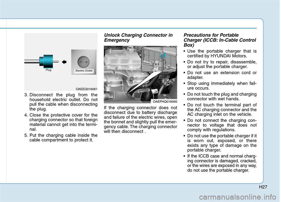
3. Disconnect the plug from the
household electric outlet. Do not
pull the cable when disconnecting
the plug.
4. Close the protective cover for the
charging connector so that foreign
material cannot get into the termi-
nal.
5. Put the charging cable inside the
cable compartment to protect it.
Unlock Charging Connector in
Emergency
If the charging connector does not
disconnect due to battery discharge
and failure of the electric wires, open
the bonnet and slightly pull the emer-
gency cable. The charging connector
will then disconnect .
Precautions for Portable
Charger (ICCB: In-Cable Control
Box)
Use the portable charger that is
certified by HYUNDAI Motors.
Do not try to repair, disassemble,
or adjust the portable charger.
Do not use an extension cord or
adapter.
Stop using immediately when fail-
ure occurs.
Do not touch the plug and charging
connector with wet hands.
Do not touch the terminal part of
the AC charging connector and the
AC charging inlet on the vehicle.
Do not connect the charging con-
nector to voltage that does not
comply with regulations.
Do not use the portable charger if it
is worn out, exposed, or there
exists any type of damage on the
portable charger.
If the ICCB case and normal charg-
ing connector is damaged, cracked,
or the wires are exposed in any way,
do not use the portable charger.
OAEEQ016061
PlugElectric Outlet
OAEPHQ016060
Page 31 of 613
H31
The hybrid system contains many
electronic components. High volt-
age components, such as cables
and other parts, may emit electro-
magnetic waves. Even when the
electromagnetic cover blocks elec-
tromagnetic emissions, electro-
magnetic waves may have an effect
on electronic devices. When your
vehicle is not used for a long period
of time, the hybrid system will dis-
charge. You need to drive the vehi-
cle several times a month. We rec-
ommend driving at least for 1 hour
or 16 km. When the hybrid battery is
discharged, or when it is impossi-
ble to jump start the vehicle, we
recommend that you contact your
HYUNDAI dealer.
Virtual Engine Sound System
(VESS)
The Virtual Engine Sound System
generates engine sound for pedestri-
ans to hear vehicle sound because
there is limited sound whilst motor
power is used.
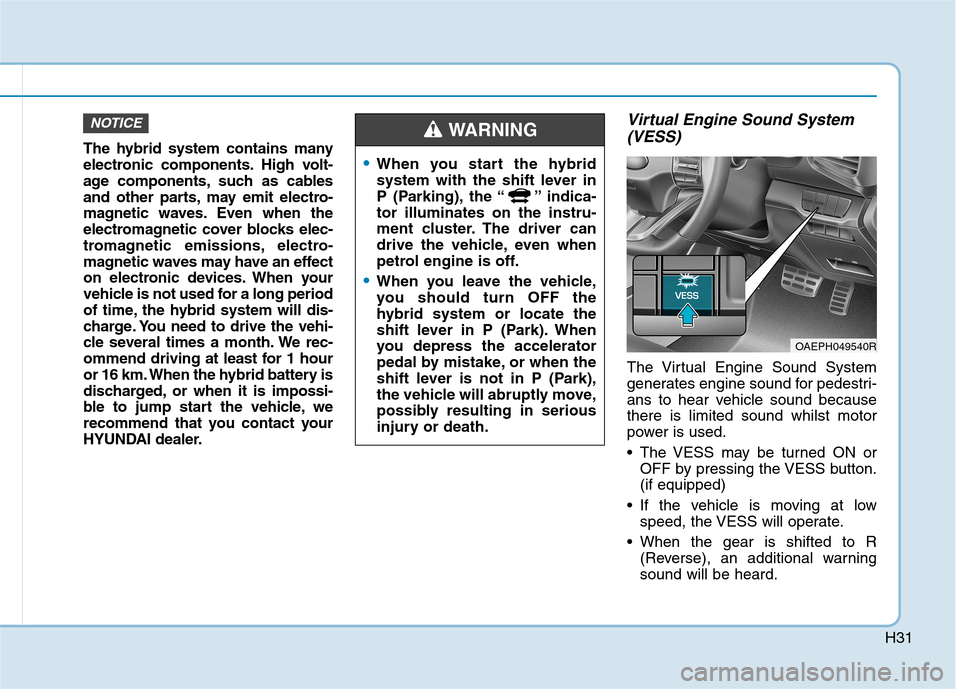
The VESS may be turned ON or
OFF by pressing the VESS button.
(if equipped)
If the vehicle is moving at low
speed, the VESS will operate.
When the gear is shifted to R
(Reverse), an additional warning
sound will be heard.
NOTICE
When you start the hybrid
system with the shift lever in
P (Parking), the “ ” indica-
tor illuminates on the instru-
ment cluster. The driver can
drive the vehicle, even when
petrol engine is off.
When you leave the vehicle,
you should turn OFF the
hybrid system or locate the
shift lever in P (Park). When
you depress the accelerator
pedal by mistake, or when the
shift lever is not in P (Park),
the vehicle will abruptly move,
possibly resulting in serious
injury or death.
WARNING
OAEPH049540R
Page 55 of 613
H55
Hybrid Battery Cooling Duct
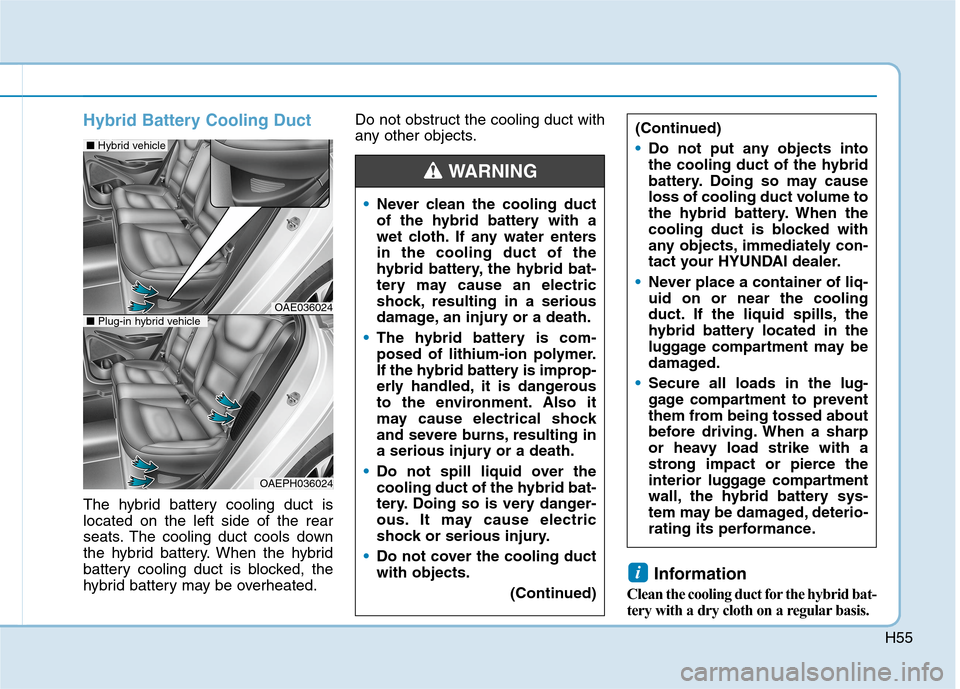
The hybrid battery cooling duct is
located on the left side of the rear
seats. The cooling duct cools down
the hybrid battery. When the hybrid
battery cooling duct is blocked, the
hybrid battery may be overheated.Do not obstruct the cooling duct with
any other objects.
Information
Clean the cooling duct for the hybrid bat-
tery with a dry cloth on a regular basis.
i
(Continued)
Do not put any objects into
the cooling duct of the hybrid
battery. Doing so may cause
loss of cooling duct volume to
the hybrid battery. When the
cooling duct is blocked with
any objects, immediately con-
tact your HYUNDAI dealer.
Never place a container of liq-
uid on or near the cooling
duct. If the liquid spills, the
hybrid battery located in the
luggage compartment may be
damaged.
Secure all loads in the lug-
gage compartment to prevent
them from being tossed about
before driving. When a sharp
or heavy load strike with a
strong impact or pierce the
interior luggage compartment
wall, the hybrid battery sys-
tem may be damaged, deterio-
rating its performance.
Never clean the cooling duct
of the hybrid battery with a
wet cloth. If any water enters
in the cooling duct of the
hybrid battery, the hybrid bat-
tery may cause an electric
shock, resulting in a serious
damage, an injury or a death.
The hybrid battery is com-
posed of lithium-ion polymer.
If the hybrid battery is improp-
erly handled, it is dangerous
to the environment. Also it
may cause electrical shock
and severe burns, resulting in
a serious injury or a death.
Do not spill liquid over the
cooling duct of the hybrid bat-
tery. Doing so is very danger-
ous. It may cause electric
shock or serious injury.
Do not cover the cooling duct
with objects.
(Continued)
WARNING
OAE036024
■Hybrid vehicle
OAEPH036024
■Plug-in hybrid vehicle
Page 66 of 613
Use of MTBE
HYUNDAI recommends avoiding
fuels containing MTBE (Methyl
Tertiary Butyl Ether) over 15.0% vol.
(Oxygen Content 2.7% weight) in
your vehicle.
Fuel containing MTBE over 15.0%
vol. (Oxygen Content 2.7% weight)
may reduce vehicle performance and
produce vapour lock or hard starting.
Your New Vehicle Limited
Warranty may not cover damage
to the fuel system and any per-
formance problems that are
caused by the use of fuels con-
taining methanol or fuels contain-
ing MTBE (Methyl Tertiary Butyl
Ether) over 15.0% vol. (Oxygen
Content 2.7% weight.)
Do not use methanol
Fuels containing methanol (wood
alcohol) should not be used in your
vehicle.This type of fuel can reduce
vehicle performance and damage
components of the fuel system, engine
control system and emission control
system.
Fuel Additives
HYUNDAI recommends that you use
unleaded petrol which has an
Octane Rating of RON (Research
Octane Number) 91 or higher.
For customers who do not use good
quality petrols, and have problems
starting or the engine does not run
smoothly, one bottle of additive added
to the fuel tank is recommended
according to the maintenance sched-
ule (refer to chapter 7, “Normal
Maintenance Schedule”).
Additives are available from your
authorised HYUNDAI dealer along
with information on how to use them.
Do not mix other additives.
NOTICE
F9
Introduction
Page 72 of 613
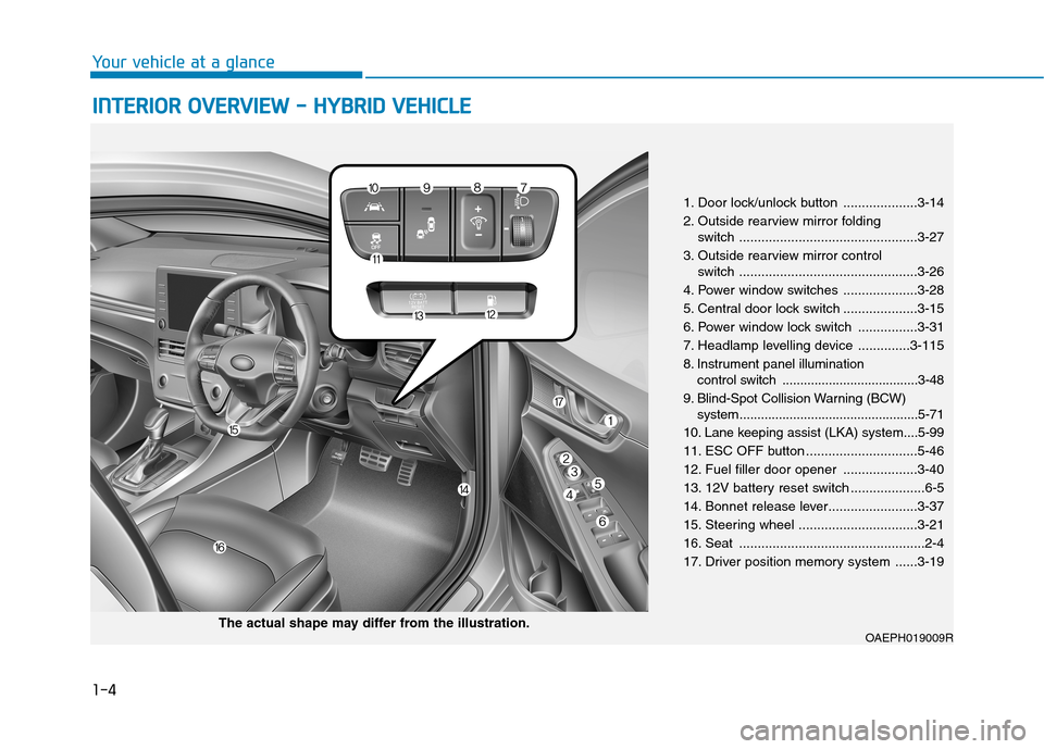
1-4
Your vehicle at a glance
I IN
NT
TE
ER
RI
IO
OR
R
O
OV
VE
ER
RV
VI
IE
EW
W
-
-
H
HY
YB
BR
RI
ID
D
V
VE
EH
HI
IC
CL
LE
E
1. Door lock/unlock button ....................3-14
2. Outside rearview mirror folding
switch ................................................3-27
3. Outside rearview mirror control
switch ................................................3-26
4. Power window switches ....................3-28
5. Central door lock switch ....................3-15
6. Power window lock switch ................3-31
7. Headlamp levelling device ..............3-115
8. Instrument panel illumination
control switch ......................................3-48
9. Blind-Spot Collision Warning (BCW)
system ..................................................5-71
10. Lane keeping assist (LKA) system....5-99
11. ESC OFF button ..............................5-46
12. Fuel filler door opener ....................3-40
13. 12V battery reset switch ....................6-5
14. Bonnet release lever........................3-37
15. Steering wheel ................................3-21
16. Seat ..................................................2-4
17. Driver position memory system ......3-19
OAEPH019009RThe actual shape may differ from the illustration.