2020 FORD EXPEDITION height
[x] Cancel search: heightPage 46 of 542
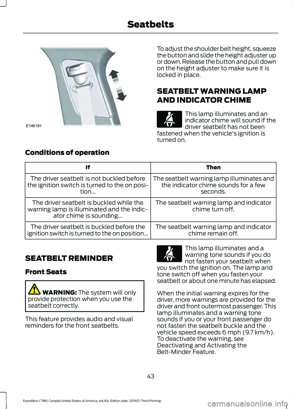
To adjust the shoulder belt height, squeeze
the button and slide the height adjuster up
or down. Release the button and pull down
on the height adjuster to make sure it is
locked in place.
SEATBELT WARNING LAMP
AND INDICATOR CHIME
This lamp illuminates and an
indicator chime will sound if the
driver seatbelt has not been
fastened when the vehicle's ignition is
turned on.
Conditions of operation Then
If
The seatbelt warning lamp illuminates andthe indicator chime sounds for a few seconds.
The driver seatbelt is not buckled before
the ignition switch is turned to the on posi- tion...
The seatbelt warning lamp and indicatorchime turn off.
The driver seatbelt is buckled while the
warning lamp is illuminated and the indic- ator chime is sounding...
The seatbelt warning lamp and indicatorchime remain off.
The driver seatbelt is buckled before the
ignition switch is turned to the on position...
SEATBELT REMINDER
Front Seats WARNING: The system will only
provide protection when you use the
seatbelt correctly.
This feature provides audio and visual
reminders for the front seatbelts. This lamp illuminates and a
warning tone sounds if you do
not fasten your seatbelt when
you switch the ignition on. The lamp and
tone switch off when you fasten your
seatbelt or about one minute has elapsed.
When the initial warning expires for the
driver, more warnings are provided for the
driver and front outermost passenger. This
lamp illuminates and a warning tone
sounds if you or your front passenger do
not fasten the seatbelt buckle and the
vehicle speed exceeds
6 mph (9.7 km/h).
To deactivate the warning, see
Deactivating and Activating the
Belt-Minder Feature.
43
Expedition (TB8) Canada/United States of America, enUSA, Edition date: 201907, Third-Printing- SeatbeltsE146191 E71880 E71880
Page 48 of 542
Read Steps 1 - 4 before starting the
procedure.
Make sure that:
•
You set the parking brake.
• The transmission is in park (P).
• The ignition is off.
• You close all vehicle doors.
• You unbuckle the driver and front
passenger seatbelts.
1. Switch the ignition on. Do not start the
engine.
2. Wait until the seatbelt warning lamp turns off (about one minute). After
Step 2, wait an additional five seconds
before proceeding with Step 3. Once
you start Step 3, you must complete
the procedure within 60 seconds.
3. For the seating position you are switching off, buckle then unbuckle the
seatbelt three times at a moderate
speed, ending in the unbuckled state.
After Step 3, the seatbelt warning lamp
turns on.
4. When the seatbelt warning lamp is on,
buckle then unbuckle the seatbelt.
After Step 4, the seatbelt warning lamp
flashes for confirmation.
• This switches the feature off if it is
currently on.
• This switches the feature on if it is
currently off.
CHILD RESTRAINT AND
SEATBELT MAINTENANCE
Inspect the vehicle seatbelts and child
safety seat systems periodically to make
sure they work properly and are not
damaged. Inspect the vehicle and child
restraint seatbelts to make sure there are
no nicks, tears or cuts. Replace if
necessary. All vehicle seatbelt assemblies,
including retractors, buckles, front seatbelt buckle assemblies, buckle support
assemblies (slide bar-if equipped),
shoulder belt height adjusters (if
equipped), shoulder belt guide on seat
backrest (if equipped), child safety seat
LATCH and tether anchors, and attaching
hardware, should be inspected after a
crash. Read the child restraint
manufacturer's instructions for additional
inspection and maintenance information
specific to the child restraint.
We recommend that all seatbelt
assemblies in use in vehicles involved in a
crash be replaced. However, if the crash
was minor and an authorized dealer finds
that the belts do not show damage and
continue to operate properly, they do not
need to be replaced. Seatbelt assemblies
not in use during a crash should also be
inspected and replaced if either damage
or improper operation is noted.
Properly care for seatbelts. See Vehicle
Care (page 343).
SEATBELT EXTENSIONS WARNING:
Persons who fit into
the vehicle's seatbelt should not use an
extension. Unnecessary use could result
in serious personal injury in the event of
a crash. WARNING:
Only use extensions
provided free of charge by our dealers.
The dealer will provide an extension
designed specifically for this vehicle,
model year and seating position. The use
of an extension intended for another
vehicle, model year or seating position
may not offer you the full protection of
your vehicle's seatbelt restraint system. WARNING:
Never use seatbelt
extensions to install child restraints.
45
Expedition (TB8) Canada/United States of America, enUSA, Edition date: 201907, Third-Printing- Seatbelts
Page 82 of 542
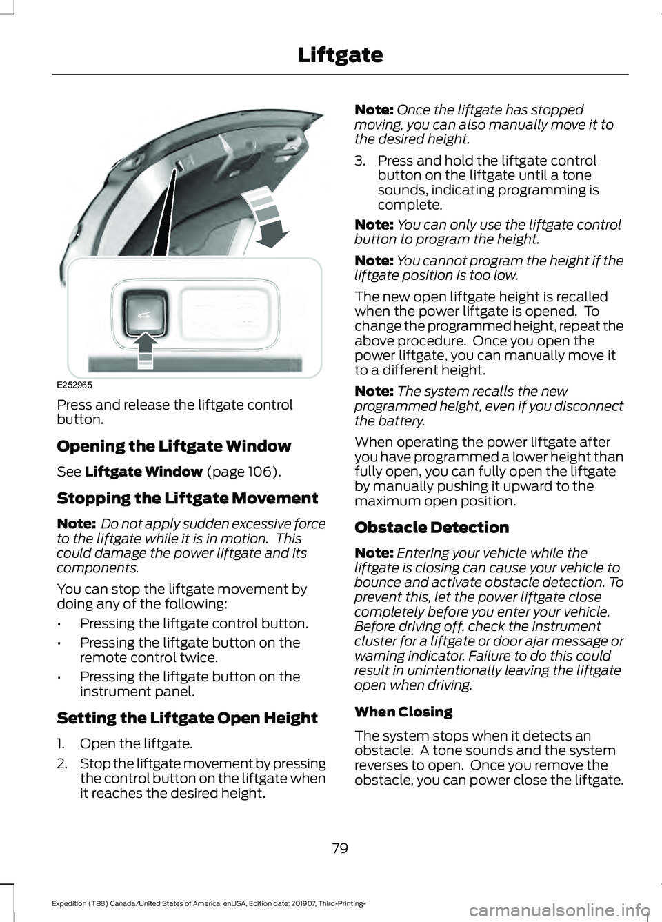
Press and release the liftgate control
button.
Opening the Liftgate Window
See Liftgate Window (page 106).
Stopping the Liftgate Movement
Note: Do not apply sudden excessive force
to the liftgate while it is in motion. This
could damage the power liftgate and its
components.
You can stop the liftgate movement by
doing any of the following:
• Pressing the liftgate control button.
• Pressing the liftgate button on the
remote control twice.
• Pressing the liftgate button on the
instrument panel.
Setting the Liftgate Open Height
1. Open the liftgate.
2. Stop the liftgate movement by pressing
the control button on the liftgate when
it reaches the desired height. Note:
Once the liftgate has stopped
moving, you can also manually move it to
the desired height.
3. Press and hold the liftgate control button on the liftgate until a tone
sounds, indicating programming is
complete.
Note: You can only use the liftgate control
button to program the height.
Note: You cannot program the height if the
liftgate position is too low.
The new open liftgate height is recalled
when the power liftgate is opened. To
change the programmed height, repeat the
above procedure. Once you open the
power liftgate, you can manually move it
to a different height.
Note: The system recalls the new
programmed height, even if you disconnect
the battery.
When operating the power liftgate after
you have programmed a lower height than
fully open, you can fully open the liftgate
by manually pushing it upward to the
maximum open position.
Obstacle Detection
Note: Entering your vehicle while the
liftgate is closing can cause your vehicle to
bounce and activate obstacle detection. To
prevent this, let the power liftgate close
completely before you enter your vehicle.
Before driving off, check the instrument
cluster for a liftgate or door ajar message or
warning indicator. Failure to do this could
result in unintentionally leaving the liftgate
open when driving.
When Closing
The system stops when it detects an
obstacle. A tone sounds and the system
reverses to open. Once you remove the
obstacle, you can power close the liftgate.
79
Expedition (TB8) Canada/United States of America, enUSA, Edition date: 201907, Third-Printing- LiftgateE252965
Page 102 of 542

WHAT IS AUTOMATIC HIGH
BEAM CONTROL
The system turns on high beams if it is dark
enough and no other traffic is present. If it
detects an approaching vehicle
’s
headlamps or tail lamps, or street lighting
ahead, the system turns the high beams
off. Low beams remain on.
A camera sensor, centrally mounted
behind the windshield of your vehicle,
continuously monitors conditions to turn
the high beams on and off.
SWITCHING AUTOMATIC HIGH
BEAM CONTROL ON AND OFF
Switch the system on or off using the
information display. See General
Information (page 114).
Activating the Automatic High
Beam Control Switch the lighting control to the
autolamps position to activate.
See
Autolamps (page 95).
Note: Automatic high beams are not
available when autolamps are not turned
on.
When active, the high beams turn on if:
• The ambient light level is low enough.
• There is no traffic in front of your
vehicle.
• The vehicle speed is greater than
approximately
32 mph (52 km/h).
When active, the high beams turn off if:
• The ambient light level is high enough
that high beams are not required.
• The system detects an approaching
vehicle's headlamps or tail lamps.
• The system detects severe rain, snow
or fog. •
The camera is blocked.
• The vehicle speed falls below
approximately
27 mph (44 km/h).
Note: The deactivation speed is lower on
curves.
Note: High beam reactivation may be
delayed in certain curvy road situations.
Note: The system may not operate properly
if the sensor is blocked. Keep the windshield
free from obstruction or damage.
Note: The system may not operate properly
in cold or inclement conditions. You can
switch on the high beams by overriding the
system.
Note: If the system detects a blockage, for
example bird droppings, bug splatter, snow
or ice, the system goes into low beam mode
until you clear the blockage. A message may
appear in the information display if the
camera is blocked.
Note: Using much larger tires or equipping
vehicle accessories such as snowplows can
modify your vehicle's ride height and
degrade automatic high beam control
performance.
AUTOMATIC HIGH BEAM
CONTROL INDICATORS The indicator illuminates to
confirm when the system is
ready to assist.
OVERRIDING AUTOMATIC
HIGH BEAM CONTROL WARNING:
The system does not
relieve you of your responsibility to drive
with due care and attention. You may
need to override the system if it does not
turn the high beams on or off.
99
Expedition (TB8) Canada/United States of America, enUSA, Edition date: 201907, Third-Printing- Automatic High Beam Control
Page 285 of 542
Measurement B has reached maximum or
minimum value:
•
Make sure that the sticker placement
instruction in step 3 of the setup has
been followed. Stickers placed outside
the allowed zone adversely affect the
system performance and could cause
improper feature function.
• Make sure that the measurement being
made is the horizontal distance only
from center of sticker to the hitch ball
center. A straight line distance that
includes any vertical rise or drop
increases the measurement and
causes an inaccurate value to be
entered into the system. See step 4 of
the setup for additional measurement
instructions.
Measurement C has reached maximum or
minimum value:
• Make sure that the sticker placement
instructions in step 3 of the setup have
been followed. Stickers placed outside
the allowed zone adversely affect the
system performance and could cause
improper feature function. If you have
met all the criteria for sticker
placement and you see this message
this sticker is either too far below or too
close to the camera to properly
recognize the sticker. In order for the
system to operate correctly the sticker
height must be lowered if you receive
the minimum warning or the sticker
height must be raised if you receive the
maximum warning.
• Only one sticker can be placed on the
trailer for correct system function. The
previous sticker must be removed or
covered so only one sticker is visible to
the camera.
• Measurement B and C must be
measured again if a new sticker is
placed on the trailer. Measurement D has reached maximum or
minimum value:
•
Make sure that the measurement being
made is the horizontal distance only
from the bumper to the center of the
single axle or the center of all the axles
on the trailer. See step 4 of the setup
for additional measurement
instructions. The TBA system does not
support trailer lengths outside the
range allowed by the information
display.
System is circling something beside the
sticker or system cannot find the sticker:
• Make sure the rear camera is clean and
the sticker is clearly visible in the
camera image. Clean the camera and
sticker if necessary.
• The camera system uses the entered
measurements to help locate the
sticker. Inaccurate sticker
measurements degrade the system ’s
ability to locate the sticker. Verify the
measurements entered into the system
are accurate.
• Remove the incorrectly circled label or
decal if possible.
• If you cannot resolve the issue a new
sticker location should be tried. The
sticker location must still meet the
requirements noted in step 3 of the
setup instructions. Only one sticker can
be placed on the trailer for correct
system function. The previous sticker
must be removed or covered so only
one sticker is visible to the camera.
Calibration
The system monitors various vehicle
parameters to ensure your vehicle is being
driven straight and the trailer straight
behind your vehicle. Any steering input or
trailer movement pauses the calibration.
282
Expedition (TB8) Canada/United States of America, enUSA, Edition date: 201907, Third-Printing- Towing
Page 293 of 542
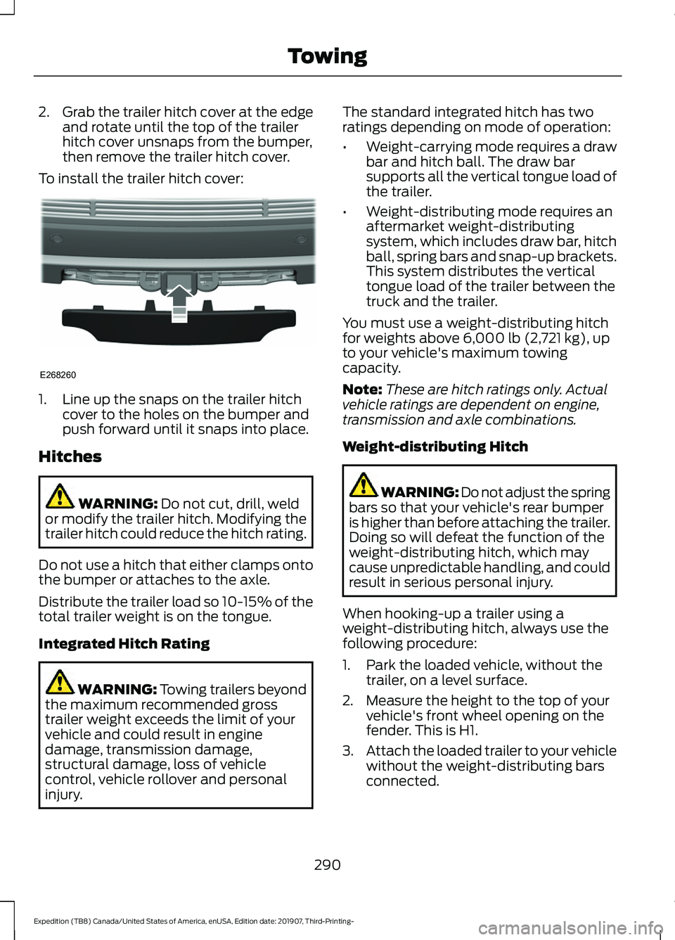
2.
Grab the trailer hitch cover at the edge
and rotate until the top of the trailer
hitch cover unsnaps from the bumper,
then remove the trailer hitch cover.
To install the trailer hitch cover: 1. Line up the snaps on the trailer hitch
cover to the holes on the bumper and
push forward until it snaps into place.
Hitches WARNING: Do not cut, drill, weld
or modify the trailer hitch. Modifying the
trailer hitch could reduce the hitch rating.
Do not use a hitch that either clamps onto
the bumper or attaches to the axle.
Distribute the trailer load so 10-15% of the
total trailer weight is on the tongue.
Integrated Hitch Rating WARNING: Towing trailers beyond
the maximum recommended gross
trailer weight exceeds the limit of your
vehicle and could result in engine
damage, transmission damage,
structural damage, loss of vehicle
control, vehicle rollover and personal
injury. The standard integrated hitch has two
ratings depending on mode of operation:
•
Weight-carrying mode requires a draw
bar and hitch ball. The draw bar
supports all the vertical tongue load of
the trailer.
• Weight-distributing mode requires an
aftermarket weight-distributing
system, which includes draw bar, hitch
ball, spring bars and snap-up brackets.
This system distributes the vertical
tongue load of the trailer between the
truck and the trailer.
You must use a weight-distributing hitch
for weights above
6,000 lb (2,721 kg), up
to your vehicle's maximum towing
capacity.
Note: These are hitch ratings only. Actual
vehicle ratings are dependent on engine,
transmission and axle combinations.
Weight-distributing Hitch WARNING: Do not adjust the spring
bars so that your vehicle's rear bumper
is higher than before attaching the trailer.
Doing so will defeat the function of the
weight-distributing hitch, which may
cause unpredictable handling, and could
result in serious personal injury.
When hooking-up a trailer using a
weight-distributing hitch, always use the
following procedure:
1. Park the loaded vehicle, without the trailer, on a level surface.
2. Measure the height to the top of your vehicle's front wheel opening on the
fender. This is H1.
3. Attach the loaded trailer to your vehicle
without the weight-distributing bars
connected.
290
Expedition (TB8) Canada/United States of America, enUSA, Edition date: 201907, Third-Printing- TowingE268260
Page 294 of 542
4. Measure the height to the top of your
vehicle's front wheel opening on the
fender a second time. This is H2.
5. Install and adjust the tension in the weight-distributing bars so that the
height of your vehicle's front wheel
opening on the fender is approximately
half the way down from H2, toward H1.
6. Check that the trailer is level or slightly
nose down toward your vehicle. If not,
adjust the ball height accordingly and
repeat steps 2-6.
When the trailer is level or slightly nose
down toward the vehicle:
• Lock the bar tension adjuster in place.
• Check that the trailer tongue securely
attaches and locks onto the hitch.
• Install safety chains, lighting, and trailer
brake controls as required by law or the
trailer manufacturer.
Safety Chains
Note: Do not attach safety chains to the
bumper. Always connect the safety chains
to the frame or hook retainers of your trailer
hitch.
Install trailer safety chains to the trailer
hitch as recommended by the
manufacturer. Cross the chains under the
trailer tongue and allow enough slack for
turning tight corners. Do not allow the
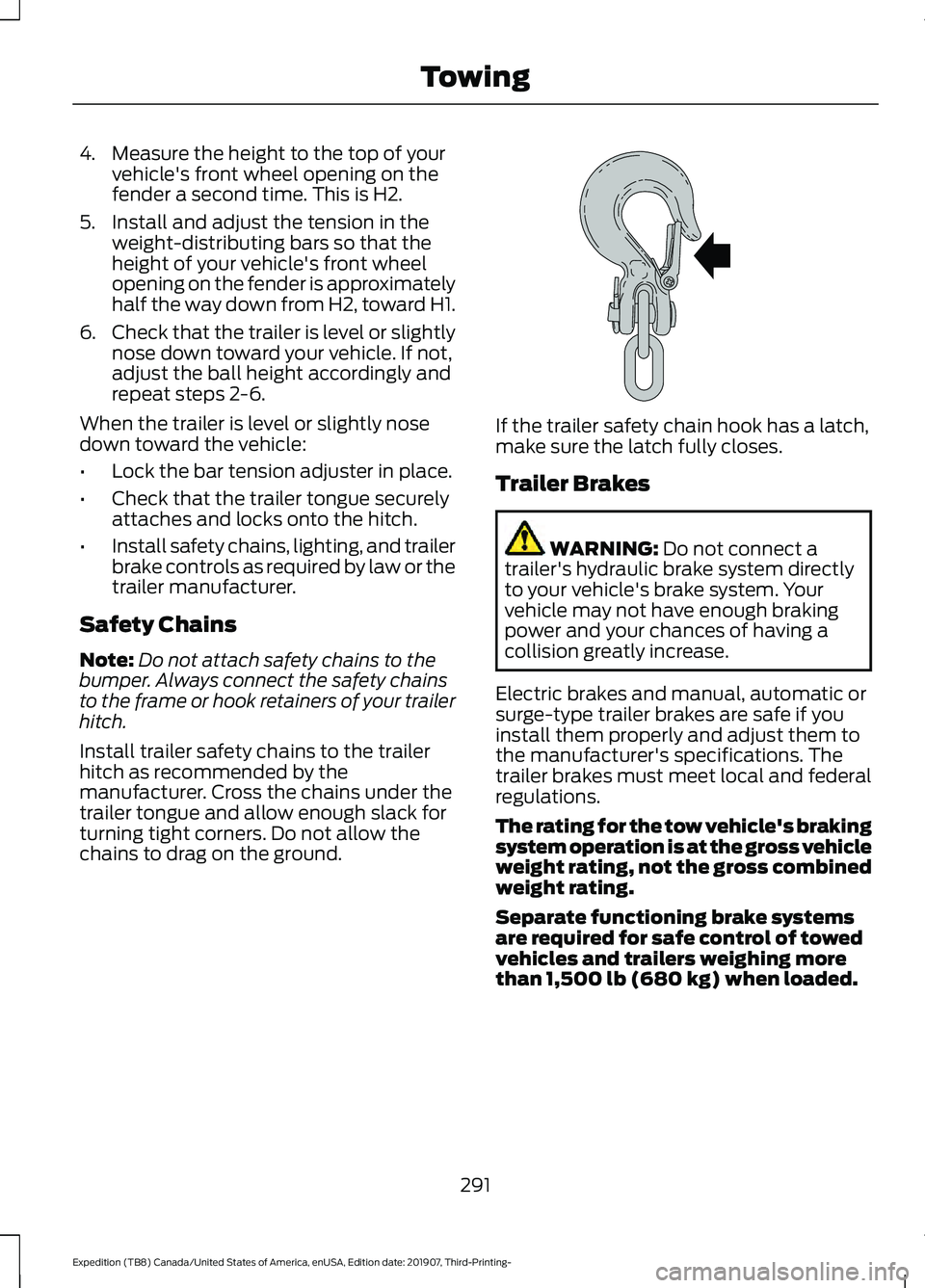
chains to drag on the ground. If the trailer safety chain hook has a latch,
make sure the latch fully closes.
Trailer Brakes
WARNING: Do not connect a
trailer's hydraulic brake system directly
to your vehicle's brake system. Your
vehicle may not have enough braking
power and your chances of having a
collision greatly increase.
Electric brakes and manual, automatic or
surge-type trailer brakes are safe if you
install them properly and adjust them to
the manufacturer's specifications. The
trailer brakes must meet local and federal
regulations.
The rating for the tow vehicle's braking
system operation is at the gross vehicle
weight rating, not the gross combined
weight rating.
Separate functioning brake systems
are required for safe control of towed
vehicles and trailers weighing more
than 1,500 lb (680 kg) when loaded.
291
Expedition (TB8) Canada/United States of America, enUSA, Edition date: 201907, Third-Printing- TowingE265060
Page 340 of 542

Make sure that you dispose of old batteries
in an environmentally friendly way. Seek
advice from your local authority about
recycling old batteries.
If storing your vehicle for more than 30
days without recharging the battery, we
recommend that you disconnect the
negative battery cable to maintain battery
charge for quick starting.
Battery Management System (If
Equipped)
The battery management system monitors
battery conditions and takes actions to
extend battery life. If excessive battery
drain is detected, the system temporarily
disables some electrical systems to
protect the battery.
Systems included are:
• Heated rear window.
• Heated seats.
• Climate control.
• Heated steering wheel.
• Audio unit.
• Navigation system.
A message may appear in the information
displays to alert you that battery
protection actions are active. These
messages are only for notification that an
action is taking place, and not intended to
indicate an electrical problem or that the
battery requires replacement.
After battery replacement, or in some
cases after charging the battery with an
external charger, the battery management
system requires eight hours of vehicle sleep
time to relearn the battery state of charge.
During this time your vehicle must remain
fully locked with the ignition switched off.
Note: Prior to relearning the battery state
of charge, the battery management system
may temporarily disable some electrical
systems. Electrical Accessory Installation
To make sure the battery management
system works correctly, do not connect an
electrical device ground connection
directly to the battery negative post. This
can cause inaccurate measurements of
the battery condition and potential
incorrect system operation.
Note:
If you add electrical accessories or
components to the vehicle, it may adversely
affect battery performance and durability.
This may also affect the performance of
other electrical systems in the vehicle.
ADJUSTING THE HEADLAMPS
Vertical Aim Adjustment
The headlamps on your vehicle are
properly aimed at the assembly plant. If
your vehicle has been in an accident,
contact an authorized dealer to check and
realign your headlamps.
Headlamp Aiming Target 8 feet (2.4 meters).
A
Center height of lamp to ground.
B
25 feet (7.6 meters).
C
Horizontal reference line.
D
337
Expedition (TB8) Canada/United States of America, enUSA, Edition date: 201907, Third-Printing- MaintenanceE142592