2020 FORD EXPEDITION ignition
[x] Cancel search: ignitionPage 295 of 542
Integrated Trailer Brake Controller (If
Equipped)
WARNING: Use the integrated
trailer brake controller to properly adjust
the trailer brakes and check all
connections before towing a trailer.
Failure to follow this instruction could
result in the loss of control of your
vehicle, personal injury or death. When used properly, the trailer brake
controller assists in smooth and effective
trailer braking by powering the trailer
’s
electric or electric-over-hydraulic brakes
with a proportional output based on the
towing vehicle ’s brake pressure.
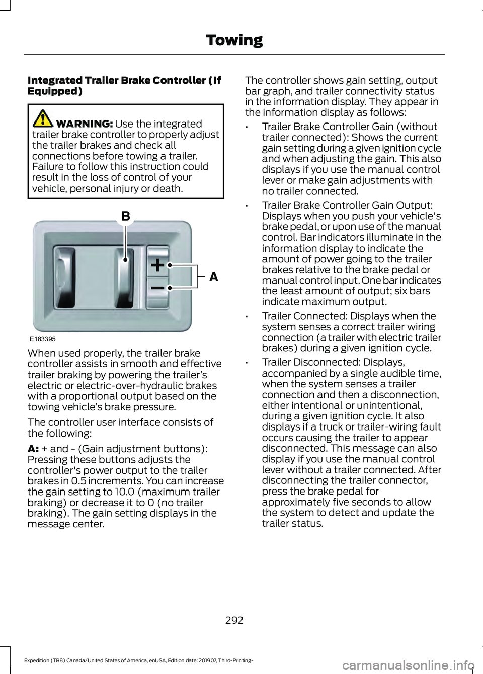
The controller user interface consists of
the following:
A:
+ and - (Gain adjustment buttons):
Pressing these buttons adjusts the
controller's power output to the trailer
brakes in 0.5 increments. You can increase
the gain setting to 10.0 (maximum trailer
braking) or decrease it to 0 (no trailer
braking). The gain setting displays in the
message center. The controller shows gain setting, output
bar graph, and trailer connectivity status
in the information display. They appear in
the information display as follows:
•
Trailer Brake Controller Gain (without
trailer connected): Shows the current
gain setting during a given ignition cycle
and when adjusting the gain. This also
displays if you use the manual control
lever or make gain adjustments with
no trailer connected.
• Trailer Brake Controller Gain Output:
Displays when you push your vehicle's
brake pedal, or upon use of the manual
control. Bar indicators illuminate in the
information display to indicate the
amount of power going to the trailer
brakes relative to the brake pedal or
manual control input. One bar indicates
the least amount of output; six bars
indicate maximum output.
• Trailer Connected: Displays when the
system senses a correct trailer wiring
connection (a trailer with electric trailer
brakes) during a given ignition cycle.
• Trailer Disconnected: Displays,
accompanied by a single audible time,
when the system senses a trailer
connection and then a disconnection,
either intentional or unintentional,
during a given ignition cycle. It also
displays if a truck or trailer-wiring fault
occurs causing the trailer to appear
disconnected. This message can also
display if you use the manual control
lever without a trailer connected. After
disconnecting the trailer connector,
press the brake pedal for
approximately five seconds to allow
the system to detect and update the
trailer status.
292
Expedition (TB8) Canada/United States of America, enUSA, Edition date: 201907, Third-Printing- TowingE183395
Page 297 of 542
wiring. Consult your trailer dealer for
assistance. This can be a short to ground
such as a chaffed wire, short to voltage
such as a pulled pin on trailer emergency
breakaway battery, or the trailer brakes
may be drawing too much current.
Points to Remember
Note:
Do not attempt removal of the trailer
brake controller without consulting the
Workshop Manual. Damage to the unit may
result.
• Adjust gain setting before using the
trailer brake controller for the first time.
• Adjust gain setting, using the procedure
above, whenever road, weather and
trailer or vehicle loading conditions
change from when the gain was initially
set.
• Only use the manual control lever for
proper adjustment of the gain during
trailer setup. Misuse, such as
application during trailer sway, could
cause instability of trailer or tow
vehicle.
• Avoid towing in adverse weather
conditions. The trailer brake controller
does not provide anti-lock control of
the trailer wheels. Trailer wheels can
lock up on slippery surfaces, resulting
in reduced stability of trailer and tow
vehicle.
• The trailer brake controller is equipped
with a feature that reduces output at
vehicle speeds below 11 mph (18 km/h)
so trailer and vehicle braking is not jerky
or harsh. This feature is only available
when applying the brakes using your
vehicle's brake pedal, not the
controller.
• The controller interacts with the brake
control system and powertrain control
system of your vehicle to provide the
best performance on different road
conditions. •
Your vehicle's brake system and the
trailer brake system work
independently of each other. Changing
the gain setting on the controller does
not affect the operation of your
vehicle's brakes whether you attach a
trailer or not.
• When you switch the engine off, the
controller output is disabled and the
display and module shut down. The
controller module and display turn on
when you switch the ignition on.
• The trailer brake controller is only a
factory-installed or dealer-installed
item. We are not responsible for
warranty or performance of the
controller due to misuse or customer
installation.
Trailer Lamps WARNING: Never connect any
trailer lamp wiring to the vehicle's tail
lamp wiring; this may damage the
electrical system resulting in fire. Contact
your authorized dealer as soon as
possible for assistance in proper trailer
tow wiring installation. Additional
electrical equipment may be required.
Trailer lamps are required on most towed
vehicles. Make sure all running lights, brake
lights, direction indicators and hazard lights
are working.
Before Towing a Trailer
Practice turning, stopping and backing up
to get the feel of your vehicle-trailer
combination before starting on a trip.
When turning, make wider turns so the
trailer wheels clear curbs and other
obstacles.
294
Expedition (TB8) Canada/United States of America, enUSA, Edition date: 201907, Third-Printing- Towing
Page 299 of 542
Replace the rear axle lubricant anytime
the rear axle has been submerged in water.
Water may have contaminated the rear
axle lubricant, which is not normally
checked or changed unless a leak is
suspected or another axle repair is
required.
TOWING THE VEHICLE ON
FOUR WHEELS
WARNING: If your vehicle has a
steering wheel lock make sure the
ignition is in the accessory or on position
when being towed.
Recreational Towing
Note: Put your climate control system in
recirculated air mode to prevent exhaust
fumes from entering your vehicle.
See
Climate Control (page 139).
Follow these guidelines if you have a need
for recreational towing, for example towing
your vehicle behind a motorhome. These
guidelines prevent damage to your
transmission.
Two-wheel Drive Vehicles
You cannot tow a two wheel drive vehicle
with any wheels on the ground as vehicle
or transmission damage may occur. You
must tow your vehicle with all four wheels
off the ground, for example when using a
car-hauling trailer.
Four-wheel Drive Vehicles Without 4x4
LOW
If your vehicle is not equipped with 4x4
Low, you cannot tow your vehicle with any
wheels on the ground or vehicle damage
may occur. You must tow your vehicle with
all four wheels off the ground, for example
when using a car-hauling trailer. Four-wheel Drive Vehicles With 4x4
LOW
You can only tow a
4X4 LOW equipped
four-wheel drive vehicle with all wheels on
the ground by placing the transfer case in
its neutral position and engaging the four
wheel down towing feature. Perform the
steps outlined in the following section after
positioning your vehicle behind the tow
vehicle and properly securing them
together.
Four-wheel-down Towing
Note: If completed successfully, the
information display shows
Neutral Tow
Enabled Leave Transmission in Neutral.
This indicates that your vehicle is safe to
tow with all wheels on the ground.
Note: If you do not see the message in the
information display, you must perform the
procedure again from the beginning.
Note: Make sure you properly secure your
vehicle to the tow vehicle.
Entering Four-wheel-down Towing
1. Start your vehicle.
2. Select
2H on the 4WD mode selector
switch.
3. For vehicles equipped with a console shifter, place the transmission in stay
in neutral mode.
See Automatic
Transmission (page 193). For vehicles
equipped with a column shifter, place
the transmission in neutral (N).
4. Once the transmission is in neutral (N)
or stay in neutral mode, switch the
engine off but leave the ignition in the
on position. The information display
shows a
Transmission Not in Park
message.
296
Expedition (TB8) Canada/United States of America, enUSA, Edition date: 201907, Third-Printing- Towing
Page 300 of 542
Note:
If your vehicle has intelligent access,
you can keep your vehicle on while switching
the engine off by pressing the
START/STOP button two times slowly
without pressing the brake pedal.
5. Press and hold the brake pedal.
6. Enable neutral tow through the information display by selecting
Settings
from the menu. See General
Information (page 114).
7. Then select
Advanced Settings.
8. Then select
Vehicle.
9. Then select
Neutral Tow.
10. Press and hold the
OK button until
the information display confirms
neutral tow is enabled.
Note: If completed successfully, the
information display shows
Neutral Tow
Enabled Leave Transmission in Neutral.
This indicates that your vehicle is safe to
tow with all wheels on the ground.
Note: If you do not see the message in the
display, you must perform the procedure
again from the beginning.
Note: You may hear an audible noise as the
transfer case shifts into its neutral position.
This is normal.
11. Leave the transmission in neutral (N).
If your vehicle has intelligent access,
press the engine
START/STOP
button once without pressing the
brake pedal to switch the ignition off.
You do not need to leave your keys in
the vehicle. You can lock and unlock
your vehicle as you normally do. If
your vehicle has a physical ignition
key, turn the ignition as far as it can
go toward the off position. It does not
turn to the off position when the
transmission is in neutral (N). You
must leave the key in the ignition
when towing. To lock and unlock your
vehicle, use the keyless entry keypad
or an extra set of keys. 12. Release the brake pedal. WARNING:
Do not disconnect the
battery during recreational towing. It
prevents the transfer case from shifting
properly and may cause the vehicle to
roll, even if the transmission is in park
(P). WARNING:
Shifting the transfer
case to its neutral position for
recreational towing may cause the
vehicle to roll, even if the transmission is
in park (P). It may injure the driver and
others. Make sure you press the foot
brake and the vehicle is in a secure, safe
position when you shift to neutral (N).
Note: Failing to put the transfer case in its
neutral position may damage vehicle
components.
Note: You can check four-wheel-down
towing status at any time by opening the
driver door or turning the ignition to the
accessory or on position and verifying the
message displays in the cluster.
Exiting Four-wheel-down Towing
To exit four-wheel-down towing and return
the transfer case to its
2H position:
1. With your vehicle still properly secured
to the tow vehicle, start the engine.
2. After starting your vehicle, switch the engine off but leave the key in the on
position.
Note: If your vehicle has intelligent access,
you can keep the vehicle on when switching
the engine off by pressing the
START/STOP
button two times slowly
without pressing the brake pedal.
3. Press and hold the brake pedal.
4. Shift the transmission out of neutral (N) and into park (P).
5. Release the brake pedal.
297
Expedition (TB8) Canada/United States of America, enUSA, Edition date: 201907, Third-Printing- Towing
Page 306 of 542
Vehicles Sold in Canada: Getting
Roadside Assistance
To fully assist you should you have a
vehicle concern, Ford Motor Company of
Canada, Limited offers a complimentary
roadside assistance program. This program
is eligible within Canada or the continental
United States.
The service is available 24 hours a day,
seven days a week.
This program is separate from the New
Vehicle Limited Warranty, but the coverage
is concurrent with the powertrain coverage
period of your vehicle. Canadian roadside
coverage and benefits may differ from the
U.S. coverage.
If you require more information, please call
us in Canada at 1-800-665-2006, or visit
our website at www.ford.ca.
HAZARD FLASHERS
Note:
The hazard flashers operate when
the ignition is in any position, or if the key is
not in the ignition. If used when the vehicle
is not running, the battery loses charge. As
a result, there may be insufficient power to
restart your vehicle. The flasher control is on the
instrument panel. Use your
hazard flashers when your
vehicle is creating a safety hazard for other
motorists.
• Press the flasher control and all front
and rear direction indicators flash.
• Press the button again to switch them
off. FUEL SHUTOFF WARNING: If your vehicle has been
involved in a crash, have the fuel system
checked. Failure to follow this instruction
could result in fire, personal injury or
death.
Note: When you try to restart your vehicle
after a fuel shutoff, the vehicle makes sure
that various systems are safe to restart.
Once the vehicle determines the systems
are safe, then the vehicle allows you to
restart.
Note: In the event that your vehicle does
not restart after your third attempt, contact
a qualified technician.
The fuel pump shutoff stops the flow of
fuel to the engine in the event of a
moderate to severe crash. Not every
impact causes a shutoff.
Should your vehicle shut off after a crash,
you may restart your vehicle.
If your vehicle has a key system:
1. Switch off the ignition.
2. Switch to start position.
3. Switch off the ignition.
4. Switch on the ignition to re-enable the
fuel pump.
5. If the vehicle does not start, repeat steps 1 through 4.
If your vehicle has a push button start
system:
1. Press START/STOP to switch off your
vehicle.
2. Press the brake pedal and START/STOP
to switch on your
vehicle.
3. Remove your foot from the brake pedal
and press
START/STOP to switch off
your vehicle.
303
Expedition (TB8) Canada/United States of America, enUSA, Edition date: 201907, Third-Printing- Roadside Emergencies
Page 325 of 542

Protected Component
Fuse Rating
Fuse
Number
Steering column control module.
7.5A
13
Smart datalink connector logic.
Brake switch.
15A
14
SYNC.
15A
15
Not used.
—
16
Not used.
—
17
Key inhibit solenoid.
7.5A
18
Gearshift module.
Telematics control unit module.
5A
19
Ignition switch.
5A
20
Humidity and in-car temperature sensor.
5A
21
Electrochromic mirror.
5A
22
Second row heated seat module.
Power window switch.
30A
23
Power mirror switch.
Left-hand front door zone module.
Moonroof logic.
30A
24
Speaker amplifier 2.
20A
25
Right-hand front door zone module.
30A
26
Left-hand rear door zone module.
30A
27
Right-hand rear door zone module.
30A
28
Adjustable pedals.
15A
29
Trailer tow control module.
5A
30
Rear climate control module.
10A
31
Drive mode switch module.
Terrain management switch.
Radio frequency transceiver module.
4x4 switch.
Audio control module.
20A
32
Not used.
—
33
322
Expedition (TB8) Canada/United States of America, enUSA, Edition date: 201907, Third-Printing- Fuses
Page 340 of 542

Make sure that you dispose of old batteries
in an environmentally friendly way. Seek
advice from your local authority about
recycling old batteries.
If storing your vehicle for more than 30
days without recharging the battery, we
recommend that you disconnect the
negative battery cable to maintain battery
charge for quick starting.
Battery Management System (If
Equipped)
The battery management system monitors
battery conditions and takes actions to
extend battery life. If excessive battery
drain is detected, the system temporarily
disables some electrical systems to
protect the battery.
Systems included are:
• Heated rear window.
• Heated seats.
• Climate control.
• Heated steering wheel.
• Audio unit.
• Navigation system.
A message may appear in the information
displays to alert you that battery
protection actions are active. These
messages are only for notification that an
action is taking place, and not intended to
indicate an electrical problem or that the
battery requires replacement.
After battery replacement, or in some
cases after charging the battery with an
external charger, the battery management
system requires eight hours of vehicle sleep
time to relearn the battery state of charge.
During this time your vehicle must remain
fully locked with the ignition switched off.
Note: Prior to relearning the battery state
of charge, the battery management system
may temporarily disable some electrical
systems. Electrical Accessory Installation
To make sure the battery management
system works correctly, do not connect an
electrical device ground connection
directly to the battery negative post. This
can cause inaccurate measurements of
the battery condition and potential
incorrect system operation.
Note:
If you add electrical accessories or
components to the vehicle, it may adversely
affect battery performance and durability.
This may also affect the performance of
other electrical systems in the vehicle.
ADJUSTING THE HEADLAMPS
Vertical Aim Adjustment
The headlamps on your vehicle are
properly aimed at the assembly plant. If
your vehicle has been in an accident,
contact an authorized dealer to check and
realign your headlamps.
Headlamp Aiming Target 8 feet (2.4 meters).
A
Center height of lamp to ground.
B
25 feet (7.6 meters).
C
Horizontal reference line.
D
337
Expedition (TB8) Canada/United States of America, enUSA, Edition date: 201907, Third-Printing- MaintenanceE142592
Page 343 of 542

3. Press the wiper blade secondary
locking clip.
4. Remove the wiper blade.
Note: Make sure that the wiper arm does
not spring back against the glass when the
wiper blade is not attached.
5. Install in the reverse order.
Note: Make sure that the wiper blade locks
into place.
REMOVING A HEADLAMP
The bumper fascia and grille must be
removed in order to remove the headlamp
assembly, see an authorized dealer if your
headlamp assembly need replacement.
CHANGING A BULB WARNING: Bulbs can become hot.
Let the bulb cool down before removing
it. Failure to do so could result in
personal injury.
Install in the reverse order unless otherwise
stated.
Note: If the bulb is accidentally touched,
clean it with rubbing alcohol before
installing it.
LED Headlamp (If Equipped)
These lamps are LED, contact an
authorized dealer.
LED Foglamp
(If Equipped)
These lamps are LED, contact an
authorized dealer.
Headlamp Bulb
1. Switch all of the lamps and the ignition
off. 2. Carefully remove the cover.
3. Disconnect the electrical connector.
4.
Turn the bulb holder counterclockwise
and remove it.
Note: You cannot separate the bulb from
the bulb holder.
Note: Do not touch the bulb glass.
Front Direction Indicator Bulb 1.
Switch all of the lamps and the ignition
off.
2. Turn the bulb holder counterclockwise
and remove it.
3. Remove the bulb by pulling it straight out.
340
Expedition (TB8) Canada/United States of America, enUSA, Edition date: 201907, Third-Printing- MaintenanceE248888 E248887