2020 DODGE CHARGER service
[x] Cancel search: servicePage 219 of 412

IN CASE OF EMERGENCY217
BULB REPLACEMENT
REPLACEMENT BULBS
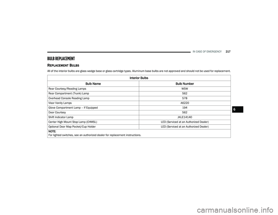
All of the interior bulbs are glass wedge base or glass cartridge types. Aluminum base bulbs are not approved and should not be used for replacement.
Interior Bulbs
Bulb Name Bulb Number
Rear Courtesy/Reading Lamps W5W
Rear Compartment (Trunk) Lamp 562
Overhead Console Reading Lamp 578
Visor Vanity Lamps A6220
Glove Compartment Lamp – If Equipped 194
Door Courtesy 562
Shift Indicator Lamp JKLE14140
Center High Mount Stop Lamp (CHMSL) LED (Serviced at an Authorized Dealer)
Optional Door Map Pocket/Cup Holder LED (Serviced at an Authorized Dealer)
NOTE:
For lighted switches, see an authorized dealer for replacement instructions.
6
20_LD_OM_EN_USC_t.book Page 217
Page 220 of 412

218IN CASE OF EMERGENCY
Exterior Bulbs
Bulb Name Bulb Number
Low/High Beam Headlamp (Standard Halogen Bi Function Projector) 9005SL+
Low/High Beam Headlamp – High Intensity Discharge (Premium HID
Bi Function Projector) D3S (Serviced at an Authorized Dealer)
Front Park/Turn Lamp LED (Serviced at an Authorized Dealer)
Front Fog Lamp – If Equipped LED (Serviced at an Authorized Dealer)
Front Side Marker LED (Serviced at an Authorized Dealer)
Rear Tail Lamp LED (Serviced at an Authorized Dealer)
Rear Stop/Turn Lamp LED (Serviced at an Authorized Dealer)
Rear Side Marker LED (Serviced at an Authorized Dealer)
Backup Lamp LED (Serviced at an Authorized Dealer)
License LED (Serviced at an Authorized Dealer)
20_LD_OM_EN_USC_t.book Page 218
Page 221 of 412

IN CASE OF EMERGENCY219
REPLACING EXTERIOR BULBS
Front Low/High Beam Headlamp — Models
With Halogen Headlamps
1. Open the hood.
Headlamp Assembly Dust Cap Location
NOTE:
Removal of the air cleaner filter housing may be
necessary prior to replacing bulbs in the head -
lamp assembly on the driver side of the vehicle.
2. Remove the large dust cap from the headlamp housing by turning it counter -
clockwise.
3. Turn the bulb counterclockwise, and remove.
Headlamp Assembly
4. Disconnect the bulb from the socket assembly and install the replacement bulb.
5. Reinstall the bulb and socket assembly into the headlamp assembly, and then turn it
clockwise.
6. Reinstall the dust cap.
Front Low/High Beam Headlamp — Models
With High Intensity Discharge (HID)
Headlamps
The headlamps are a type of high voltage
discharge tube. High voltage can remain in the
circuit even with the headlamp switch off and
the key removed. Because of this, you should
not attempt to service a headlamp bulb
yourself. If a headlamp bulb fails, take your
vehicle to an authorized dealer for service.
NOTE:
On vehicles equipped with HID headlamps,
when the headlamps are turned on, there is a
blue hue to the lights. This diminishes and
becomes more white after approximately 10
seconds, as the system charges.
CAUTION!
Do not touch the new bulb with your fingers.
Oil contamination will severely shorten bulb
life. If the bulb comes in contact with any oily
surface, clean the bulb with rubbing alcohol.
WARNING!
A transient high voltage occurs at the bulb
sockets of HID headlamps when the
headlamp switch is turned ON. It may cause
serious electrical shock or electrocution if not
serviced properly. See an authorized dealer
for service.
6
20_LD_OM_EN_USC_t.book Page 219
Page 222 of 412

220IN CASE OF EMERGENCY
(Continued)
Front/Rear Side Marker Lamp
The Side Markers use LED lamps that are not
serviceable separately. The Side Markers must
be replaced as an assembly, see an authorized
dealer.
Front Fog Lamp
The Front Fog Lamps use LED sources that are
not serviceable separately. The Front Fog Lamp
must be replaced as an assembly; see an
authorized dealer.
Front Turn Signal Lamps
The Front Park/Turn function is part of the
headlamp assembly and use LED lamps that
are not serviceable separately. The headlamps
must be replaced as an assembly, see an
authorized dealer.
Backup Lamps
The Backup Lamps use LED sources that are
not serviceable separately. The Applique must
be replaced as an assembly; see an authorized
dealer.
License Lamp
The License Lamp uses an LED source that is
not serviceable separately. The License Lamp
must be replaced as an assembly; see an
authorized dealer.
Center High Mounted Stop Lamp (CHMSL)
The CHMSL Lamp uses LED sources that are
not serviceable separately. The CHMSL Lamp
must be replaced as an assembly; see an
authorized dealer.
FUSES
GENERAL INFORMATION
The fuses protect electrical systems against
excessive current.
When a device does not work, you must check
the fuse element inside the blade fuse for a
break/melt.
WARNING!
When replacing a blown fuse, always use
an appropriate replacement fuse with the
same amp rating as the original fuse. Never
replace a fuse with another fuse of higher
amp rating. Never replace a blown fuse with
metal wires or any other material. Do not
place a fuse inside a circuit breaker cavity
or vice versa. Failure to use proper fuses
may result in serious personal injury, fire
and/or property damage.
Before replacing a fuse, make sure that the
ignition is off and that all the other services
are switched off and/or disengaged.
If the replaced fuse blows again, contact an
authorized dealer.
If a general protection fuse for safety
systems (air bag system, braking system),
power unit systems (engine system, trans-
mission system) or steering system blows,
contact an authorized dealer.
WARNING! (Continued)
20_LD_OM_EN_USC_t.book Page 220
Page 231 of 412

IN CASE OF EMERGENCY229
(Continued)
(Continued)
JACKING AND TIRE CHANGING
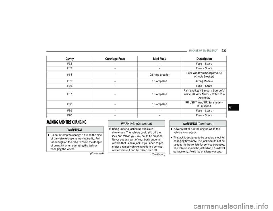
F62
––Fuse – Spare
F63 ––Fuse – Spare
F64 –25 Amp Breaker Rear Windows (Charger/300)
(Circuit Breaker)
F65 –10 Amp Red Airbag Module
F66 ––Fuse – Spare
F67 –10 Amp RedRain and Light Sensor / Sunroof /
Inside RR View Mirror / Police Run Acc Relay
F68 –10 Amp RedRR USB Timer/ RR Sunshade –
If Equipped
F69 ––Fuse – Spare
F70 ––Fuse – Spare
CavityCartridge Fuse Mini-FuseDescription
WARNING!
Do not attempt to change a tire on the side
of the vehicle close to moving traffic. Pull
far enough off the road to avoid the danger
of being hit when operating the jack or
changing the wheel.
Being under a jacked-up vehicle is
dangerous. The vehicle could slip off the
jack and fall on you. You could be crushed.
Never put any part of your body under a
vehicle that is on a jack. If you need to get
under a raised vehicle, take it to a service
center where it can be raised on a lift.
WARNING! (Continued)
Never start or run the engine while the
vehicle is on a jack.
The jack is designed to be used as a tool for
changing tires only. The jack should not be
used to lift the vehicle for service purposes.
The vehicle should be jacked on a firm level
surface only. Avoid ice or slippery areas.
WARNING! (Continued)
6
20_LD_OM_EN_USC_t.book Page 229
Page 233 of 412

IN CASE OF EMERGENCY231
(Continued)
Wheel Chocks
NOTE:
Passengers should not remain in the vehicle
when the vehicle is being lifted or raised.
JACKING AND CHANGING A TIRE
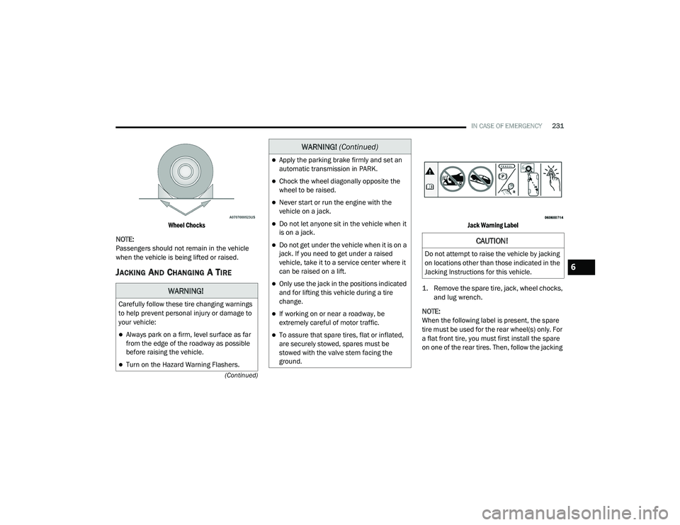
Jack Warning Label
1. Remove the spare tire, jack, wheel chocks, and lug wrench.
NOTE:
When the following label is present, the spare
tire must be used for the rear wheel(s) only. For
a flat front tire, you must first install the spare
on one of the rear tires. Then, follow the jacking
WARNING!
Carefully follow these tire changing warnings
to help prevent personal injury or damage to
your vehicle:
Always park on a firm, level surface as far
from the edge of the roadway as possible
before raising the vehicle.
Turn on the Hazard Warning Flashers.
Apply the parking brake firmly and set an
automatic transmission in PARK.
Chock the wheel diagonally opposite the
wheel to be raised.
Never start or run the engine with the
vehicle on a jack.
Do not let anyone sit in the vehicle when it
is on a jack.
Do not get under the vehicle when it is on a
jack. If you need to get under a raised
vehicle, take it to a service center where it
can be raised on a lift.
Only use the jack in the positions indicated
and for lifting this vehicle during a tire
change.
If working on or near a roadway, be
extremely careful of motor traffic.
To assure that spare tires, flat or inflated,
are securely stowed, spares must be
stowed with the valve stem facing the
ground.
WARNING! (Continued)
CAUTION!
Do not attempt to raise the vehicle by jacking
on locations other than those indicated in the
Jacking Instructions for this vehicle.
6
20_LD_OM_EN_USC_t.book Page 231
Page 236 of 412

234IN CASE OF EMERGENCY
ROAD TIRE INSTALLATION
1. Mount the road tire on the axle.
2. Install the remaining lug nuts with the cone
shaped end of the nut toward the wheel.
Lightly tighten the lug nuts. 3. Lower the vehicle to the ground by turning
the jack handle counterclockwise.
4. Refer to “Wheel And Tire Torque Specifi -
cations” in “Technical Specifications” for
proper lug nut torque.
5. After 25 miles (40 km), check the lug nut torque with a torque wrench to ensure that
all lug nuts are properly seated against the
wheel.TIRE SERVICE KIT — IF EQUIPPED
Small punctures up to 1/4 inch (6 mm) in the
tire tread can be sealed with Tire Service Kit.
Foreign objects (e.g., screws or nails) should not
be removed from the tire. Tire Service Kit can be
used in outside temperatures down to
approximately -4°F (-20°C). This kit will provide a temporary tire seal,
allowing you to drive your vehicle up to
100 miles (160 km) with a maximum speed of
50 mph (80 km/h).
TIRE SERVICE KIT STORAGE
The Tire Service Kit is located in the trunk.
Tire Service Kit Location
WARNING!
A loose tire or jack thrown forward in a collision
or hard stop could endanger the occupants of
the vehicle. Always stow the jack parts and the
spare tire in the places provided. Have the
deflated (flat) tire repaired or replaced
immediately.
WARNING!
To avoid the risk of forcing the vehicle off the
jack, do not tighten the wheel nuts fully until
the vehicle has been lowered. Failure to
follow this warning may result in serious
injury.
20_LD_OM_EN_USC_t.book Page 234
Page 237 of 412

IN CASE OF EMERGENCY235
TIRE SERVICE KIT COMPONENTS AND
O
PERATION
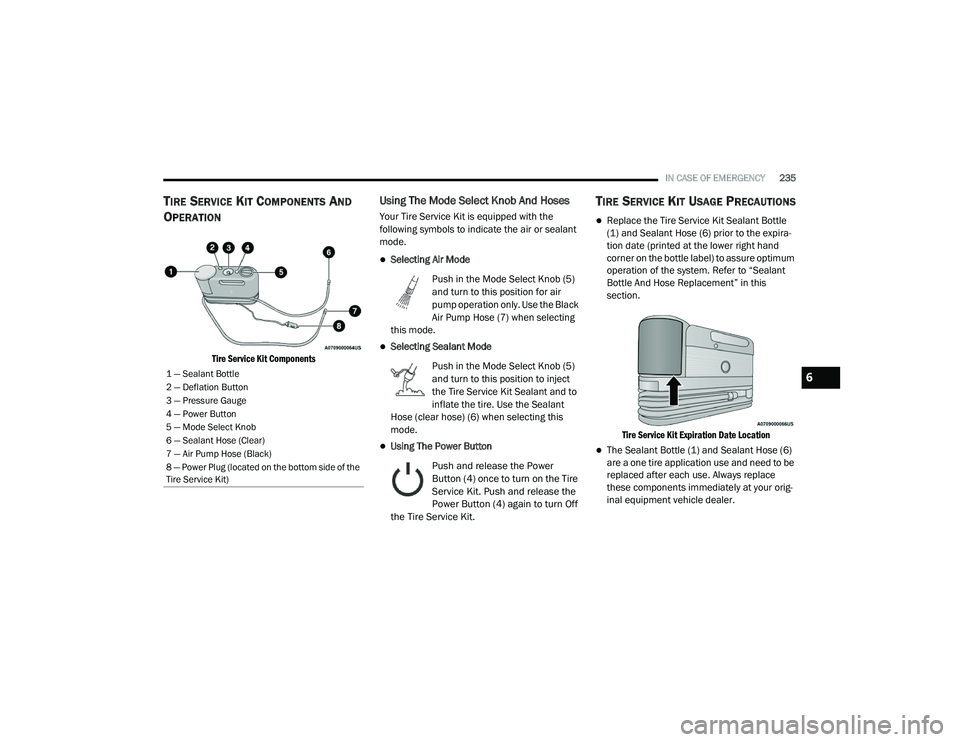
Tire Service Kit Components
Using The Mode Select Knob And Hoses
Your Tire Service Kit is equipped with the
following symbols to indicate the air or sealant
mode.
Selecting Air Mode
Push in the Mode Select Knob (5)
and turn to this position for air
pump operation only. Use the Black
Air Pump Hose (7) when selecting
this mode.
Selecting Sealant Mode
Push in the Mode Select Knob (5)
and turn to this position to inject
the Tire Service Kit Sealant and to
inflate the tire. Use the Sealant
Hose (clear hose) (6) when selecting this
mode.
Using The Power Button
Push and release the Power
Button (4) once to turn on the Tire
Service Kit. Push and release the
Power Button (4) again to turn Off
the Tire Service Kit.
TIRE SERVICE KIT USAGE PRECAUTIONS
Replace the Tire Service Kit Sealant Bottle
(1) and Sealant Hose (6) prior to the expira -
tion date (printed at the lower right hand
corner on the bottle label) to assure optimum
operation of the system. Refer to “Sealant
Bottle And Hose Replacement” in this
section.
Tire Service Kit Expiration Date Location
The Sealant Bottle (1) and Sealant Hose (6)
are a one tire application use and need to be
replaced after each use. Always replace
these components immediately at your orig -
inal equipment vehicle dealer.
1 — Sealant Bottle
2 — Deflation Button
3 — Pressure Gauge
4 — Power Button
5 — Mode Select Knob
6 — Sealant Hose (Clear)
7 — Air Pump Hose (Black)
8 — Power Plug (located on the bottom side of the
Tire Service Kit)6
20_LD_OM_EN_USC_t.book Page 235