2020 DODGE CHARGER steering
[x] Cancel search: steeringPage 144 of 412

142SAFETY
(Continued)
Maintaining Your Air Bag System Event Data Recorder (EDR)
This vehicle is equipped with an event data
recorder (EDR). The main purpose of an EDR is
to record, in certain crash or near crash-like
situations, such as an air bag deployment or
hitting a road obstacle, data that will assist in
understanding how a vehicle’s systems
performed. The EDR is designed to record data
related to vehicle dynamics and safety systems
for a short period of time, typically 30 seconds
or less. The EDR in this vehicle is designed to
record such data as:
How various systems in your vehicle were
operating;
Whether or not the driver and passenger
safety belts were buckled/fastened;
How far (if at all) the driver was depressing
the accelerator and/or brake pedal; and,
How fast the vehicle was traveling.
WARNING!
Modifications to any part of the air bag
system could cause it to fail when you need
it. You could be injured if the air bag system
is not there to protect you. Do not modify
the components or wiring, including adding
any kind of badges or stickers to the
steering wheel hub trim cover or the upper
passenger side of the instrument panel. Do
not modify the front bumper, vehicle body
structure, or add aftermarket side steps or
running boards.
It is dangerous to try to repair any part of
the air bag system yourself. Be sure to tell
anyone who works on your vehicle that it
has an air bag system.
Do not attempt to modify any part of your
air bag system. The air bag may inflate acci-
dentally or may not function properly if
modifications are made. Take your vehicle
to an authorized dealer for any air bag
system service. If your seat, including your
trim cover and cushion, needs to be
serviced in any way (including removal or
loosening/tightening of seat attachment
bolts), take the vehicle to an authorized
dealer. Only manufacturer approved seat
accessories may be used. If it is necessary
to modify the air bag system for persons
with disabilities, contact an authorized
dealer.
WARNING! (Continued)
20_LD_OM_EN_USC_t.book Page 142
Page 174 of 412

172STARTING AND OPERATING
3. Push and hold the ignition switch until the
engine turns off.
4. Wait approximately 30 seconds.
5. Restart the engine.
6. Shift into the desired gear range. If the problem is no longer detected, the
transmission will return to normal
operation.
NOTE:
Even if the transmission can be reset, we
recommend that you visit an authorized dealer
at your earliest possible convenience. An autho -
rized dealer has diagnostic equipment to
assess the condition of your transmission.
If the transmission cannot be reset, authorized
dealer service is required.
AutoStick — If Equipped
AutoStick is a driver-interactive transmission
feature providing manual shift control, giving
you more control of the vehicle. AutoStick
allows you to maximize engine braking,
eliminate undesirable upshifts and downshifts,
and improve overall vehicle performance. This system can also provide you with more
control during passing, city driving, cold slippery
conditions, mountain driving, trailer towing, and
many other situations.
Operation
When the gear selector is in the DRIVE (D)
position, the transmission will operate
automatically, shifting between the eight
available gears. To activate AutoStick, move the
gear selector into the MANUAL (M) position
(beside the DRIVE position). The current
transmission gear will be displayed in the
instrument cluster, along with a highlighted "M"
(Manual) indication. When the gear selector is
in the MANUAL (M) position, tap the gear
selector forward (-) or tap the (-) shift paddle on
the steering wheel (if equipped) to downshift
the transmission to the next lower gear, or tap
the lever rearward (+) or tap the (+) shift paddle
(if equipped) to command an upshift.
Paddle Shifters
NOTE:
Tapping one of the steering wheel-mounted
shift paddles (+/-) (if equipped) while the gear
selector is in DRIVE, will activate a temporary
AutoStick mode. Tapping (-) to enter AutoStick
mode will downshift the transmission to the
next lower gear, while tapping (+) to enter
AutoStick mode will retain the current gear.
The current gear will be displayed in the instru -
ment cluster, but the "M" will not be high -
lighted. The transmission will revert back to
normal operation (if the gear selector remains
in DRIVE) after a period of time, depending on
accelerator pedal activity.
1 — Shift Paddle Downshift
2 — Shift Paddle Upshift
20_LD_OM_EN_USC_t.book Page 172
Page 176 of 412

174STARTING AND OPERATING
SPORT MODE — WITHOUT PERFORMANCE
CONTROL
Your vehicle is equipped with a SPORT Mode
feature. This mode is a configuration set up for
typical enthusiast driving. The engine,
transmission, and steering systems are all set
to their SPORT settings. SPORT Mode will
provide improved throttle response and
modified shifting for an enhanced driving
experience, as well the greatest amount of
steering feel. This mode may be activated and
deactivated by pushing the Sport button on the
instrument panel switch bank.
For vehicles equipped with Drive Modes or a
“SUPER TRACK PAK” button, refer to “Drive
Mode Supplement” for further information.
FUEL SAVER TECHNOLOGY 5.7L AND 6.4L
ONLY — IF EQUIPPED
This feature offers improved fuel economy by
shutting off four of the engine's eight cylinders
during light load and cruise conditions. The
system is automatic with no driver inputs or
additional driving skills required.
NOTE:
This system may take some time to return to full
functionality after a battery disconnect.
ELECTRIC POWER STEERING
The Electric Power Steering system will give you
good vehicle response and increased ease of
maneuverability in tight spaces. The system will
vary its assist to provide light efforts while
parking and good feel while driving. If the
electric steering system experiences a fault that
prevents it from providing assist, you will still
have the ability to steer the vehicle manually. If the Electric Power Steering Fault
Warning Light is displayed and the
“SERVICE POWER STEERING” or the
“POWER STEERING ASSIST OFF –
SERVICE SYSTEM” message is displayed within
the instrument cluster display, this indicates the
vehicle needs to be taken to the dealer for
service. Refer to “Warning Lights And
Messages” in “Getting To Know Your
Instrument Panel” for further information.
NOTE:
Even if the power steering assistance is no longer
operational, it is still possible to steer the vehicle.
Under these conditions there will be a substantial
increase in steering effort, especially at low
speeds and during parking maneuvers.
If the condition persists, see an authorized
dealer for service.
WARNING!
Do not downshift for additional engine
braking on a slippery surface. The drive
wheels could lose their grip and the vehicle
could skid, causing a collision or personal
injury.
WARNING!
Continued operation with reduced assist
could pose a safety risk to yourself and
others. Service should be obtained as soon
as possible.
20_LD_OM_EN_USC_t.book Page 174
Page 177 of 412

STARTING AND OPERATING175
If the Electric Power Steering Fault Warning
Light is displayed and the “POWER STEERING
SYSTEM OVER TEMP” message is displayed on
the instrument cluster screen, they indicate that
extreme steering maneuvers may have
occurred which caused an over temperature
condition in the power steering system. Once
driving conditions are safe, pull over and let the
vehicle idle for a few moments until the Electric
Power Steering Fault Warning Light and
message turn off.
SPEED CONTROL — IF EQUIPPED
When engaged, the Speed Control takes over
accelerator operations at speeds greater than
25 mph (40 km/h) or 20 mph (32 km/h),
depending on engine size and axle ratio.
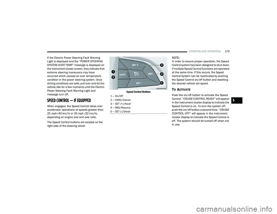
The Speed Control buttons are located on the
right side of the steering wheel.
Speed Control Buttons
NOTE:
In order to ensure proper operation, the Speed
Control system has been designed to shut down
if multiple Speed Control functions are operated
at the same time. If this occurs, the Speed
Control System can be reactivated by pushing
the Speed Control on/off button and resetting
the desired vehicle set speed.
TO ACTIVATE
Push the on/off button to activate the Speed
Control. “CRUISE CONTROL READY” will appear
in the instrument cluster display to indicate the
Speed Control is on. To turn the system off,
push the on/off button a second time. “CRUISE
CONTROL OFF” will appear in the instrument
cluster display to indicate the Speed Control is
off. The system should be turned off when not
in use.
1 — On/Off
2 — CANC/Cancel
3 — SET (+)/Accel
4 — RES/Resume
5 — SET (-)/Decel
5
20_LD_OM_EN_USC_t.book Page 175
Page 181 of 412

STARTING AND OPERATING179
ADAPTIVE CRUISE CONTROL (ACC)
O
PERATION
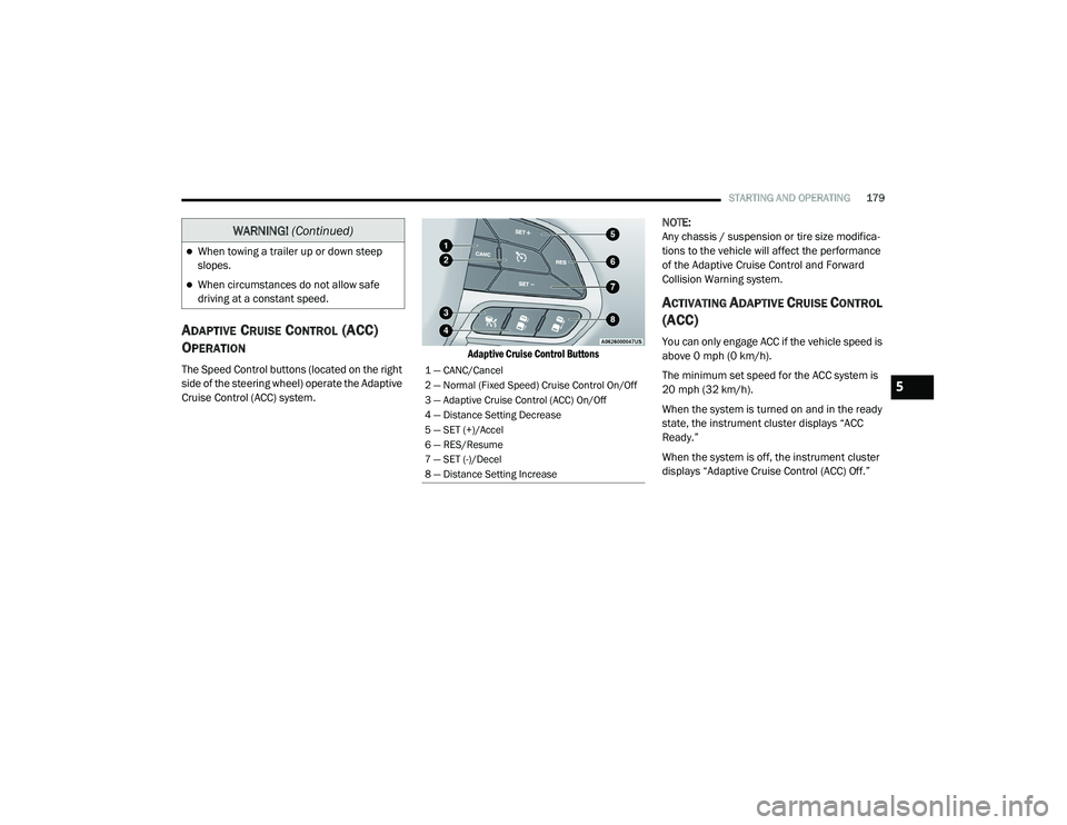
The Speed Control buttons (located on the right
side of the steering wheel) operate the Adaptive
Cruise Control (ACC) system.
Adaptive Cruise Control Buttons
NOTE:
Any chassis / suspension or tire size modifica
-
tions to the vehicle will affect the performance
of the Adaptive Cruise Control and Forward
Collision Warning system.
ACTIVATING ADAPTIVE CRUISE CONTROL
(ACC)
You can only engage ACC if the vehicle speed is
above 0 mph (0 km/h).
The minimum set speed for the ACC system is
20 mph (32 km/h).
When the system is turned on and in the ready
state, the instrument cluster displays “ACC
Ready.”
When the system is off, the instrument cluster
displays “Adaptive Cruise Control (ACC) Off.”
When towing a trailer up or down steep
slopes.
When circumstances do not allow safe
driving at a constant speed.
WARNING! (Continued)
1 — CANC/Cancel
2 — Normal (Fixed Speed) Cruise Control On/Off
3 — Adaptive Cruise Control (ACC) On/Off
4 — Distance Setting Decrease
5 — SET (+)/Accel
6 — RES/Resume
7 — SET (-)/Decel
8 — Distance Setting Increase
5
20_LD_OM_EN_USC_t.book Page 179
Page 187 of 412

STARTING AND OPERATING185
ADAPTIVE CRUISE CONTROL (ACC)
M
ENU
The instrument cluster display will show the
current ACC system settings. The instrument
cluster display is located in the center of the
instrument cluster. The information it displays
depends on ACC system status.
Push the Adaptive Cruise Control (ACC) on/off
button (located on the steering wheel) until one
of the following appears in the instrument
cluster display:
Adaptive Cruise Control Off
When ACC is deactivated, the display will read
“Adaptive Cruise Control Off.”
Adaptive Cruise Control Ready
When ACC is activated, but the vehicle speed
setting has not been selected, the display will
read “Adaptive Cruise Control Ready.”
Adaptive Cruise Control Set
When the SET (+) or the SET (-) button (located
on the steering wheel) is pushed, the display will
read “ACC SET.” When ACC is set, the set speed will show in the
instrument cluster display.
The ACC screen may display once again if any
ACC activity occurs, which may include any of
the following:
System Cancel
Driver Override
System Off
ACC Proximity Warning
ACC Unavailable Warning
The instrument cluster display will return to
the last display selected after five seconds of
no ACC display activity
DISPLAY WARNINGS AND
M
AINTENANCE
“Wipe Front Radar Sensor In Front Of
Vehicle” Warning
The “ACC/FCW Unavailable Wipe Front Radar
Sensor” warning will display and also a chime
will indicate when conditions temporarily limit
system performance. This most often occurs at times of poor visibility,
such as in snow or heavy rain. The ACC system
may also become temporarily blinded due to
obstructions, such as mud, dirt or ice. In these
cases, the instrument cluster display will display
“ACC/FCW Unavailable Wipe Front Radar
Sensor” and the system will deactivate.
The “ACC/FCW Unavailable Wipe Front Radar
Sensor” message can sometimes be displayed
while driving in highly reflective areas (i.e.
tunnels with reflective tiles, or ice and snow).
The ACC system will recover after the vehicle
has left these areas. Under rare conditions,
when the radar is not tracking any vehicles or
objects in its path this warning may temporarily
occur.
NOTE:
If the “ACC/FCW Unavailable Wipe Front Radar
Sensor” warning is active Normal (Fixed Speed)
Cruise Control is still available. For additional
information refer to “Normal (Fixed Speed)
Cruise Control Mode” in this section.
If weather conditions are not a factor, the driver
should examine the sensor. It may require
cleaning or removal of an obstruction. The
sensor is located in the center of the vehicle
behind the lower grille.
5
20_LD_OM_EN_USC_t.book Page 185
Page 198 of 412

196STARTING AND OPERATING
(Continued)
object as a sensor problem, causing the
“PARKSENSE UNAVAILABLE SERVICE
REQUIRED” message to be shown in the
instrument cluster display.
LANESENSE — IF EQUIPPED
LANESENSE OPERATION
The LaneSense system is operational at speeds
above 37 mph (60 km/h) and below 112 mph
(180 km/h). The LaneSense system uses a
forward looking camera to detect lane markings
and measure vehicle position within the lane
boundaries.
When both lane markings are detected and the
driver unintentionally drifts out of the lane (no
turn signal applied), the LaneSense system
provides a haptic warning in the form of torque
applied to the steering wheel to prompt the
driver to remain within the lane boundaries. If
the driver continues to unintentionally drift out
of the lane, the LaneSense system provides a
visual warning through the instrument cluster
display to prompt the driver to remain within the
lane boundaries. The driver may manually override the haptic
warning by applying torque into the steering
wheel at any time.
When only a single lane marking is detected
and the driver unintentionally drifts across the
lane marking (no turn signal applied), the
LaneSense system provides visual warnings
through the instrument cluster display to
prompt the driver to remain within the lane.
When only a single lane marking is detected, a
haptic (torque) warning will not be provided.
NOTE:
When operating conditions have been met, the
LaneSense system will monitor if the driver’s
hands are on the steering wheel and provides
an audible warning to the driver when the
driver’s hands are not detected on the steering
wheel. The system will cancel if the driver does
not return their hands to the wheel.
TURNING LANESENSE ON OR OFF
The default status of LaneSense is off.
The LaneSense button is located on the center
stack below the Uconnect display.
WARNING!
Drivers must be careful when backing up
even when using the Rear Park Assist system.
Always check carefully behind your vehicle,
and be sure to check for pedestrians,
animals, other vehicles, obstructions, or blind
spots before backing up. You are responsible
for the safety of your surroundings and must
continue to pay attention while backing up.
Failure to do so can result in serious injury or
death.
CAUTION!
ParkSense is only a parking aid and it is
unable to recognize every obstacle,
including small obstacles. Parking curbs
might be temporarily detected or not
detected at all. Obstacles located above or
below the sensors will not be detected
when they are in close proximity.
The vehicle must be driven slowly when
using ParkSense in order to be able to stop
in time when an obstacle is detected. It is
recommended that the driver looks over
his/her shoulder when using ParkSense.
CAUTION!
(Continued)
20_LD_OM_EN_USC_t.book Page 196
Page 199 of 412

STARTING AND OPERATING197
To turn the LaneSense system on,
push the LaneSense button (LED
turns off). A “LaneSense On”
message is shown in the instrument
cluster display.
To turn the LaneSense system off, push the
LaneSense button once (LED turns on).
NOTE:
The LaneSense system will retain the last
system state, on or off, from the last ignition
cycle when the ignition is changed to the ON/
RUN position.
LANESENSE WARNING MESSAGE
The LaneSense system will indicate the current
lane drift condition through the instrument
cluster display.
Premium Instrument Cluster Display Screen —
If Equipped
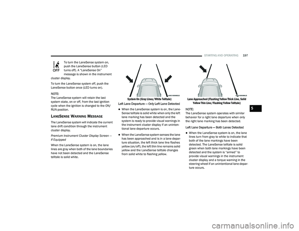
When the LaneSense system is on, the lane
lines are gray when both of the lane boundaries
have not been detected and the LaneSense
telltale is solid white.
System On (Gray Lines/White Telltale)
Left Lane Departure — Only Left Lane Detected
When the LaneSense system is on, the Lane-
Sense telltale is solid white when only the left
lane marking has been detected and the
system is ready to provide visual warnings in
the instrument cluster display if an uninten -
tional lane departure occurs.
When the LaneSense system senses the lane
has been approached and is in a lane depar -
ture situation, the left thick lane line flashes
yellow (on/off), the left thin line remains solid
yellow and the LaneSense telltale changes
from solid white to flashing yellow.
Lane Approached (Flashing Yellow Thick Line, Solid
Yellow Thin Line/Flashing Yellow Telltale)
NOTE:
The LaneSense system operates with similar
behavior for a right lane departure when only
the right lane marking has been detected.
Left Lane Departure — Both Lanes Detected When the LaneSense system is on, the lane
lines turn from gray to white to indicate that
both of the lane markings have been
detected. The LaneSense telltale is solid
green when both lane markings have been
detected and the system is “armed” to
provide visual warnings in the instrument
cluster display and a torque warning in the
steering wheel if an unintentional lane depar -
ture occurs.
5
20_LD_OM_EN_USC_t.book Page 197