2020 DODGE CHARGER change wheel
[x] Cancel search: change wheelPage 124 of 412

122SAFETY
NOTE:
The TPMS is not intended to replace normal
tire care and maintenance or to provide
warning of a tire failure or condition.
The TPMS should not be used as a tire pres -
sure gauge while adjusting your tire pressure.
Driving on a significantly under-inflated tire
causes the tire to overheat and can lead to
tire failure. Under-inflation also reduces fuel
efficiency and tire tread life, and may affect
the vehicle’s handling and stopping ability.
The TPMS is not a substitute for proper tire
maintenance, and it is the driver’s responsi -
bility to maintain correct tire pressure using
an accurate tire pressure gauge, even if
under-inflation has not reached the level to
trigger illumination of the TPMS Warning
Light.
Seasonal temperature changes will affect
tire pressure, and the TPMS will monitor the
actual tire pressure in the tire.
Premium System
The Tire Pressure Monitoring System (TPMS)
uses wireless technology with wheel rim
mounted electronic sensors to monitor tire
pressure levels. Sensors, mounted to each
wheel as part of the valve stem, transmit tire
pressure readings to the receiver module.
NOTE:
It is particularly important for you to check the
tire pressure in all of the tires on your vehicle
monthly and to maintain the proper pressure.
The TPMS consists of the following
components:
Receiver module
Four Tire Pressure Monitoring sensors
Various Tire Pressure Monitoring System
messages, which display in the instrument
cluster
Tire Pressure Monitoring System Warning
Light
Tire Pressure Monitoring Low Pressure
Warnings
The Tire Pressure Monitoring System
(TPMS) Warning Light will illuminate
in the instrument cluster and a chime
will sound when tire pressure is low in one or
more of the four active road tires. In addition,
the instrument cluster will display an “Inflate to
XX” message and a graphic showing the
pressure values of each tire with the low tire
pressure values shown in a different color.
Tire Pressure Monitoring Display
20_LD_OM_EN_USC_t.book Page 122
Page 125 of 412

SAFETY123
Should this occur, you should stop as soon as
possible and inflate the tires with a low pressure
condition (those shown in a different color in the
instrument cluster graphic) to the vehicle’s
recommended cold placard pressure inflation
value as shown in the “Inflate to XX” message.
Once the system receives the updated tire
pressures, the system will automatically
update, the graphic display in the instrument
cluster will change color back to the original
color, and the TPMS Warning Light will turn off.
The vehicle may need to be driven for up to
20 minutes above 15 mph (24 km/h) in order
for the TPMS to receive this information.
NOTE:
When filling warm tires, the tire pressure may
need to be increased up to an additional 4 psi
(28 kPa) above the recommended cold placard
pressure in order to turn the TPMS Warning
Light off.
Low Tire Pressure Monitoring Display
Service Tire Pressure System Warning
If a system fault is detected, the Tire Pressure
Monitoring System (TPMS) Warning Light will
flash on and off for 75 seconds and then remain
on solid. The system fault will also sound a
chime. In addition, the instrument cluster will
display a "Service Tire Pressure System"
message for a minimum of five seconds and
then display dashes (- -) in place of the pressure
value to indicate which sensor is not being
received.If the ignition switch is cycled, this sequence will
repeat, providing the system fault still exists. If
the system fault no longer exists, the TPMS
Warning Light will no longer flash, and the
"Service Tire Pressure System" message will no
longer display, and a pressure value will display
in place of the dashes. A system fault can occur
due to any of the following:
Signal interference due to electronic devices
or driving next to facilities emitting the same
radio frequencies as the TPM sensors.
Accumulation of snow or ice around the
wheels or wheel housings.
Using tire chains on the vehicle.
Using wheels/tires not equipped with TPM
sensors.
4
20_LD_OM_EN_USC_t.book Page 123
Page 159 of 412

SAFETY157
(Continued)
PERIODIC SAFETY CHECKS YOU SHOULD
M
AKE OUTSIDE THE VEHICLE
Tires
Examine tires for excessive tread wear and
uneven wear patterns. Check for stones, nails,
glass, or other objects lodged in the tread or
sidewall. Inspect the tread for cuts and cracks.
Inspect sidewalls for cuts, cracks, and bulges.
Check the wheel nuts for tightness. Check the
tires (including spare) for proper cold inflation
pressure.
Lights
Have someone observe the operation of brake
lights and exterior lights while you work the
controls. Check turn signal and high beam
indicator lights on the instrument panel.
ONLY use the driver’s side floor mat on the
driver’s side floor area. To check for inter -
ference, with the vehicle properly parked
with the engine off, fully depress the accel -
erator, the brake, and the clutch pedal (if
present) to check for interference. If your
floor mat interferes with the operation of
any pedal, or is not secure to the floor,
remove the floor mat from the vehicle and
place the floor mat in your trunk.
ONLY use the passenger’s side floor mat on
the passenger’s side floor area.
ALWAYS make sure objects cannot fall or slide
into the driver’s side floor area when the
vehicle is moving. Objects can become trapped
under accelerator, brake, or clutch pedals and
could cause a loss of vehicle control.
WARNING! (Continued)
NEVER place any objects under the floor
mat (e.g., towels, keys, etc.). These objects
could change the position of the floor mat
and may cause interference with the accel -
erator, brake, or clutch pedals.
If the vehicle carpet has been removed and
re-installed, always properly attach carpet
to the floor and check the floor mat
fasteners are secure to the vehicle carpet.
Fully depress each pedal to check for inter -
ference with the accelerator, brake, or
clutch pedals then re-install the floor mats.
It is recommended to only use mild soap
and water to clean your floor mats. After
cleaning, always check your floor mat has
been properly installed and is secured to
your vehicle using the floor mat fasteners
by lightly pulling mat.
WARNING! (Continued)
4
20_LD_OM_EN_USC_t.book Page 157
Page 166 of 412

164STARTING AND OPERATING
300 to 500 miles (483 to 805 km) :
Exercise the full engine RPM range, shifting
manually at higher RPM when possible.
Do not perform sustained operation with the
accelerator pedal at wide open throttle.
Maintain vehicle speed below 85 mph
(136 km/h) and observe local speed limits.
For the first 1,500 miles (2,414 km):
Do not participate in track events, sport
driving schools, or similar activities during
the first 1,500 miles (2,414 km).
NOTE:
Check engine oil with every refueling and add if
necessary. Oil and fuel consumption may be
higher through the first oil change interval.
Running the engine with an oil level below the
add mark can cause severe engine damage.
PARKING BRAKE
Before leaving the vehicle, make sure that the
parking brake is fully applied and place the gear
selector in the PARK position. The foot operated parking brake is located
below the lower left corner of the instrument
panel. To apply the park brake, firmly push the
parking brake pedal fully. To release the parking
brake, press the parking brake pedal a second
time and let your foot up as you feel the brake
disengage.
Parking Brake
When the parking brake is applied with the
ignition switch in the ON/RUN position, the
Brake Warning Light in the instrument cluster
will illuminate. NOTE:
When the parking brake is applied and the
transmission is placed in gear, the Brake
Warning Light will flash. If vehicle speed is
detected, a chime will sound to alert the
driver. Fully release the parking brake before
attempting to move the vehicle.
This light only shows that the parking brake is
applied. It does not show the degree of brake
application.
When parking on a hill, it is important to turn the
front wheels toward the curb on a downhill
grade and away from the curb on an uphill
grade. Apply the parking brake before placing
the gear selector in PARK, otherwise the load on
the transmission locking mechanism may make
it difficult to move the gear selector out of PARK.
The parking brake should always be applied
whenever the driver is not in the vehicle.
20_LD_OM_EN_USC_t.book Page 164
Page 199 of 412

STARTING AND OPERATING197
To turn the LaneSense system on,
push the LaneSense button (LED
turns off). A “LaneSense On”
message is shown in the instrument
cluster display.
To turn the LaneSense system off, push the
LaneSense button once (LED turns on).
NOTE:
The LaneSense system will retain the last
system state, on or off, from the last ignition
cycle when the ignition is changed to the ON/
RUN position.
LANESENSE WARNING MESSAGE
The LaneSense system will indicate the current
lane drift condition through the instrument
cluster display.
Premium Instrument Cluster Display Screen —
If Equipped
When the LaneSense system is on, the lane
lines are gray when both of the lane boundaries
have not been detected and the LaneSense
telltale is solid white.
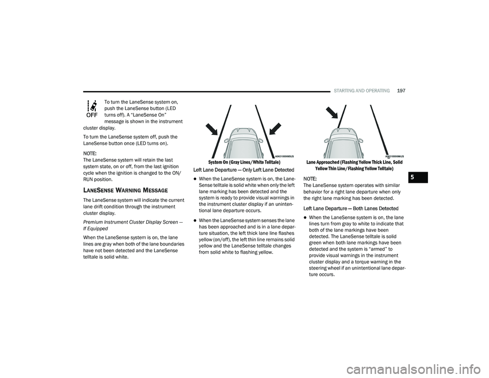
System On (Gray Lines/White Telltale)
Left Lane Departure — Only Left Lane Detected
When the LaneSense system is on, the Lane-
Sense telltale is solid white when only the left
lane marking has been detected and the
system is ready to provide visual warnings in
the instrument cluster display if an uninten -
tional lane departure occurs.
When the LaneSense system senses the lane
has been approached and is in a lane depar -
ture situation, the left thick lane line flashes
yellow (on/off), the left thin line remains solid
yellow and the LaneSense telltale changes
from solid white to flashing yellow.
Lane Approached (Flashing Yellow Thick Line, Solid
Yellow Thin Line/Flashing Yellow Telltale)
NOTE:
The LaneSense system operates with similar
behavior for a right lane departure when only
the right lane marking has been detected.
Left Lane Departure — Both Lanes Detected When the LaneSense system is on, the lane
lines turn from gray to white to indicate that
both of the lane markings have been
detected. The LaneSense telltale is solid
green when both lane markings have been
detected and the system is “armed” to
provide visual warnings in the instrument
cluster display and a torque warning in the
steering wheel if an unintentional lane depar -
ture occurs.
5
20_LD_OM_EN_USC_t.book Page 197
Page 200 of 412

198STARTING AND OPERATING
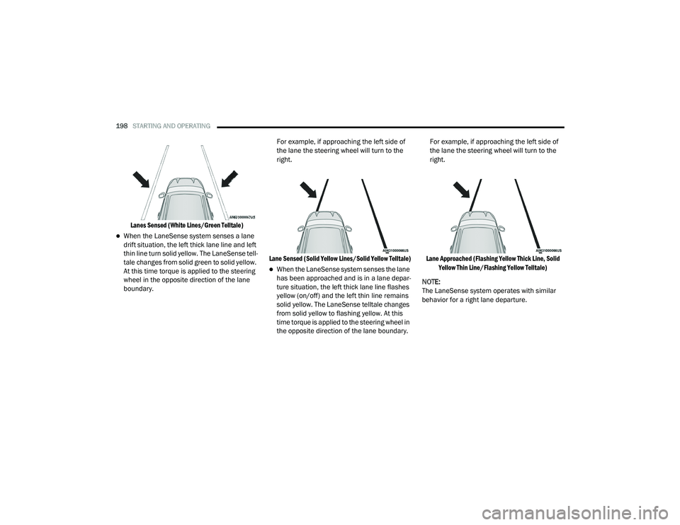
Lanes Sensed (White Lines/Green Telltale)
When the LaneSense system senses a lane
drift situation, the left thick lane line and left
thin line turn solid yellow. The LaneSense tell -
tale changes from solid green to solid yellow.
At this time torque is applied to the steering
wheel in the opposite direction of the lane
boundary. For example, if approaching the left side of
the lane the steering wheel will turn to the
right.
Lane Sensed (Solid Yellow Lines/Solid Yellow Telltale)
When the LaneSense system senses the lane
has been approached and is in a lane depar -
ture situation, the left thick lane line flashes
yellow (on/off) and the left thin line remains
solid yellow. The LaneSense telltale changes
from solid yellow to flashing yellow. At this
time torque is applied to the steering wheel in
the opposite direction of the lane boundary. For example, if approaching the left side of
the lane the steering wheel will turn to the
right.
Lane Approached (Flashing Yellow Thick Line, Solid Yellow Thin Line/Flashing Yellow Telltale)
NOTE:
The LaneSense system operates with similar
behavior for a right lane departure.
20_LD_OM_EN_USC_t.book Page 198
Page 201 of 412

STARTING AND OPERATING199
CHANGING LANESENSE STATUS
The LaneSense system settings can be
configured through the Uconnect system
screen.
Follow these steps to change the LaneSense
settings:
1. Press the “Controls” button located on the
bottom of the Uconnect touchscreen
display.
2. Press the “Settings” button.
3. Press the “Safety & Driving Assistance” button.
When in the Safety & Driving Assistance screen,
you can configure the intensity of the torque
warning and the warning zone sensitivity (early/
late) through the personalization settings.
NOTE:
When enabled the system operates above
37 mph (60 km/h) and below 112 mph (180 km/h).
Use of the turn signal suppresses the warn -
ings.
The system will not apply torque to the
steering wheel whenever a safety system
engages. (Anti-Lock Brakes, Traction Control
System, Electronic Stability Control, Forward
Collision Warning, etc.)
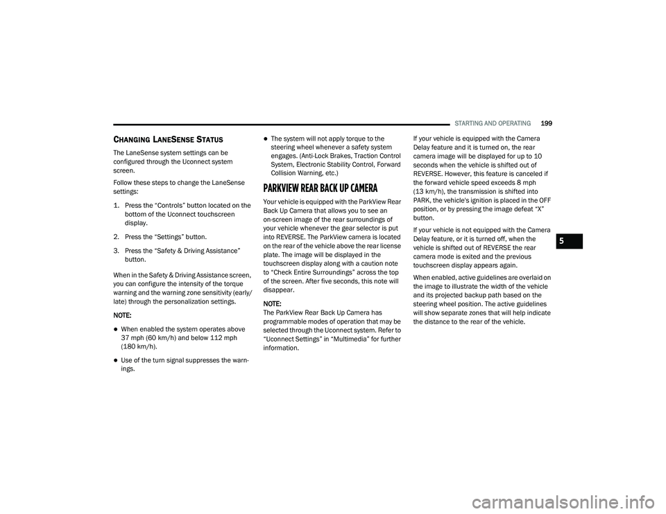
PARKVIEW REAR BACK UP CAMERA
Your vehicle is equipped with the ParkView Rear
Back Up Camera that allows you to see an
on-screen image of the rear surroundings of
your vehicle whenever the gear selector is put
into REVERSE. The ParkView camera is located
on the rear of the vehicle above the rear license
plate. The image will be displayed in the
touchscreen display along with a caution note
to “Check Entire Surroundings” across the top
of the screen. After five seconds, this note will
disappear.
NOTE:
The ParkView Rear Back Up Camera has
programmable modes of operation that may be
selected through the Uconnect system. Refer to
“Uconnect Settings” in “Multimedia” for further
information. If your vehicle is equipped with the Camera
Delay feature and it is turned on, the rear
camera image will be displayed for up to 10
seconds when the vehicle is shifted out of
REVERSE. However, this feature is canceled if
the forward vehicle speed exceeds 8 mph
(13 km/h), the transmission is shifted into
PARK, the vehicle's ignition is placed in the OFF
position, or by pressing the image defeat “X”
button.
If your vehicle is not equipped with the Camera
Delay feature, or it is turned off, when the
vehicle is shifted out of REVERSE the rear
camera mode is exited and the previous
touchscreen display appears again.
When enabled, active guidelines are overlaid on
the image to illustrate the width of the vehicle
and its projected backup path based on the
steering wheel position. The active guidelines
will show separate zones that will help indicate
the distance to the rear of the vehicle.
5
20_LD_OM_EN_USC_t.book Page 199
Page 231 of 412

IN CASE OF EMERGENCY229
(Continued)
(Continued)
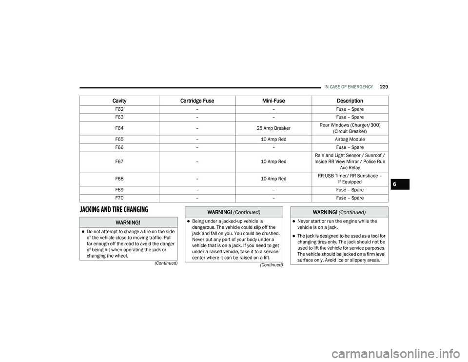
JACKING AND TIRE CHANGING
F62
––Fuse – Spare
F63 ––Fuse – Spare
F64 –25 Amp Breaker Rear Windows (Charger/300)
(Circuit Breaker)
F65 –10 Amp Red Airbag Module
F66 ––Fuse – Spare
F67 –10 Amp RedRain and Light Sensor / Sunroof /
Inside RR View Mirror / Police Run Acc Relay
F68 –10 Amp RedRR USB Timer/ RR Sunshade –
If Equipped
F69 ––Fuse – Spare
F70 ––Fuse – Spare
CavityCartridge Fuse Mini-FuseDescription
WARNING!
Do not attempt to change a tire on the side
of the vehicle close to moving traffic. Pull
far enough off the road to avoid the danger
of being hit when operating the jack or
changing the wheel.
Being under a jacked-up vehicle is
dangerous. The vehicle could slip off the
jack and fall on you. You could be crushed.
Never put any part of your body under a
vehicle that is on a jack. If you need to get
under a raised vehicle, take it to a service
center where it can be raised on a lift.
WARNING! (Continued)
Never start or run the engine while the
vehicle is on a jack.
The jack is designed to be used as a tool for
changing tires only. The jack should not be
used to lift the vehicle for service purposes.
The vehicle should be jacked on a firm level
surface only. Avoid ice or slippery areas.
WARNING! (Continued)
6
20_LD_OM_EN_USC_t.book Page 229