2020 DODGE CHARGER spare tire
[x] Cancel search: spare tirePage 7 of 412

5
PARKSENSE REAR PARK ASSIST —
IF EQUIPPED ....................................................... 191 ParkSense Sensors ...................................192
ParkSense Warning Display ......................192
ParkSense Display ..................................... 192Enabling And Disabling ParkSense ..........194
Service The ParkSense Rear Park
Assist System .............................................195 Cleaning The ParkSense System ..............195
ParkSense System Usage Precautions ....195
LANESENSE — IF EQUIPPED ........................... 196
LaneSense Operation ................................196Turning LaneSense On Or Off ...................196LaneSense Warning Message ..................197
Changing LaneSense Status .....................199
PARKVIEW REAR BACK UP CAMERA ............. 199
REFUELING THE VEHICLE ................................. 200
VEHICLE LOADING ............................................ 202
Vehicle Certification Label ........................ 202Gross Vehicle Weight Rating (GVWR) .......202
Gross Axle Weight Rating (GAWR) ........... 202Overloading ................................................202
Loading ......................................................203
TRAILER TOWING .............................................. 203
Common Towing Definitions .....................203Trailer Hitch Classification ........................ 205Trailer Towing Weights (Maximum Trailer
Weight Ratings) ..........................................205 Trailer And Tongue Weight ....................... 206
Towing Requirements................................ 206
Towing Tips ................................................ 209
RECREATIONAL TOWING (BEHIND MOTORHOME,
ETC.) ....................................................................210
DRIVING TIPS ...................................................... 210
Driving On Slippery Surfaces .................... 210
Driving Through Water .............................. 211
IN CASE OF EMERGENCY
HAZARD WARNING FLASHERS .......................212
ASSIST AND SOS MIRROR — IF EQUIPPED .... 212General Information .................................. 216
BULB REPLACEMENT ........................................ 217
Replacement Bulbs ................................... 217
Replacing Exterior Bulbs ........................... 219
FUSES ..................................................................220
General Information .................................. 220Underhood Fuses ...................................... 221
Rear Interior Fuses .................................... 225
JACKING AND TIRE CHANGING ........................229
Jack Location/Spare Tire Stowage ........... 230
Preparations For Jacking........................... 230
Jacking And Changing A Tire ..................... 231Road Tire Installation ................................ 234 TIRE SERVICE KIT — IF EQUIPPED ................... 234
Tire Service Kit Storage............................. 234
Tire Service Kit Components And
Operation ................................................... 235 Tire Service Kit Usage Precautions .......... 235Sealing A Tire With Tire Service Kit .......... 237
JUMP STARTING ............................................... 240
Preparations For Jump Start ..................... 240
Jump Starting Procedure .......................... 241
IF YOUR ENGINE OVERHEATS ......................... 242
MANUAL PARK RELEASE — 8 – SPEED
TRANSMISSION ................................................. 243
FREEING A STUCK VEHICLE ............................. 244
SRT — TOWING A DISABLED VEHICLE ............ 246
NON SRT — TOWING A DISABLED VEHICLE ... 248 All Wheel Drive (AWD) Models .................. 249Rear-Wheel Drive (RWD) Models ............. 249
ENHANCED ACCIDENT RESPONSE SYSTEM
(EARS) ................................................................ 249
EVENT DATA RECORDER (EDR) ....................... 249
SERVICING AND MAINTENANCE
SCHEDULED SERVICING .................................. 250
3.6L And 5.7L Engines ............................. 250
6.2L Supercharged And 6.4L Engines ..... 254
20_LD_OM_EN_USC_t.book Page 5
Page 8 of 412

6
ENGINE COMPARTMENT .................................. 266 3.6L Engine ...............................................2665.7L Engine ...............................................2676.2L Supercharged Engine ......................268
6.4L Engine ...............................................269Checking Oil Level — 3.6L And 5.7L
Engine.........................................................270 Checking Oil Level — 6.2L Supercharged
Engine And 6.4L Engine ...........................270 Adding Washer Fluid..................................270Maintenance-Free Battery .......................271
Pressure Washing ......................................271
DEALER SERVICE .............................................. 272
Engine Oil .................................................. 272Engine Oil Filter ..........................................274Engine Air Cleaner Filter ...........................275
Air Conditioner Maintenance ...................275Accessory Drive Belt Inspection................276Body Lubrication ........................................277
Windshield Wiper Blades ..........................278
Exhaust System .........................................279
Cooling System .........................................280
Brake System ............................................284
Automatic Transmission ............................285
Rear Axle ....................................................286
RAISING THE VEHICLE ...................................... 286 TIRES....................................................................286
Tire Safety Information ............................. 286Tires — General Information .................... 293
Tire Types ................................................... 298
Spare Tires — If Equipped ......................... 298
Wheel And Wheel Trim Care .................... 300
Tire Chains And Traction Devices —
Non-SRT ..................................................... 301 Tire Chains And Traction Devices — SRT.. 302
Tire Rotation Recommendations —
Non-SRT ..................................................... 302
Tire Rotation Recommendations — SRT .... 303
DEPARTMENT OF TRANSPORTATION UNIFORM
TIRE QUALITY GRADES .....................................303
Treadwear .................................................. 303
Traction Grades ......................................... 303
Temperature Grades ................................. 304
VEHICLE STORAGE .............................................304
BODYWORK ........................................................ 304
Protection From Atmospheric Agents....... 304
Body And Underbody Maintenance .......... 305Preserving The Bodywork .......................... 305
INTERIORS ......................................................... 306
Seats And Fabric Parts .............................. 306
Plastic And Coated Parts ........................... 306
Leather Parts ............................................. 307
Glass Surfaces .......................................... 307
TECHNICAL SPECIFICATIONS
IDENTIFICATION DATA ...................................... 308Vehicle Identification Number .................. 308
BRAKE SYSTEM ................................................ 308
WHEEL AND TIRE TORQUE
SPECIFICATIONS ................................................ 308
Torque Specifications................................ 308
FUEL REQUIREMENTS ...................................... 309
3.6L Engine ................................................ 309
5.7L Engine ................................................ 310
6.2L And 6.4L Engine................................ 310
Reformulated Gasoline ............................ 310Materials Added To Fuel ........................... 310
Gasoline/Oxygenate Blends ..................... 311
Do Not Use E-85 In Non-Flex Fuel
Vehicles ...................................................... 311 CNG And LP Fuel System Modifications .. 312MMT In Gasoline........................................ 312
Fuel System Cautions................................ 312
Carbon Monoxide Warnings...................... 312
FLUID CAPACITIES — NON-SRT ....................... 313
FLUID CAPACITIES — SRT ................................ 314
FLUIDS AND LUBRICANTS — NON-SRT .......... 315 Engine ........................................................ 315
Chassis ....................................................... 317
FLUIDS AND LUBRICANTS — SRT ................... 318
Engine ........................................................ 318
Chassis ....................................................... 320
20_LD_OM_EN_USC_t.book Page 6
Page 101 of 412

GETTING TO KNOW YOUR INSTRUMENT PANEL99
The “ESC OFF Indicator Light” and the “ESC
Indicator Light” come on momentarily each
time the ignition is placed in the ON/RUN or
ACC/ON/RUN position.
The ESC system will make buzzing or clicking
sounds when it is active. This is normal; the
sounds will stop when ESC becomes inactive.
This light will come on when the vehicle is in
an ESC event.
Electronic Stability Control (ESC) OFF
Warning Light — If Equipped
This warning light indicates the
Electronic Stability Control (ESC) is
off.
Each time the ignition is turned to ON/RUN or
ACC/ON/RUN, the ESC system will be on, even
if it was turned off previously.
The ESC OFF indicator will be lit any time the
Traction Mode is set to Sport, Track or Full OFF
in Drive Modes.
Low Washer Fluid Warning Light —
If Equipped
This warning light will illuminate when
the windshield washer fluid is low.
Refer to “Engine Compartment” in
“Servicing And Maintenance” for further
information.
Tire Pressure Monitoring System (TPMS)
Warning Light
The warning light switches on and a
message is displayed to indicate that
the tire pressure is lower than the
recommended value and/or that slow
pressure loss is occurring. In these cases,
optimal tire duration and fuel consumption may
not be guaranteed.
Should one or more tires be in the condition
mentioned above, the display will show the
indications corresponding to each tire. Each tire, including the spare (if provided),
should be checked monthly when cold and
inflated to the inflation pressure recommended
by the vehicle manufacturer on the vehicle
placard or tire inflation pressure label. If your
vehicle has tires of a different size than the size
indicated on the vehicle placard or tire inflation
pressure label, you should determine the
proper tire inflation pressure for those tires.
CAUTION!
Do not continue driving with one or more flat
tires as handling may be compromised. Stop
the vehicle, avoiding sharp braking and
steering. If a tire puncture occurs, repair
immediately using the dedicated tire repair
kit and contact an authorized dealer as soon
as possible.
3
20_LD_OM_EN_USC_t.book Page 99
Page 126 of 412

124SAFETY
Vehicles With Compact Spare
1. The compact spare tire or non-matching
full size does not have a Tire Pressure
Monitoring sensor. Therefore, the TPMS
will not monitor the pressure in the
compact or non-matching full size spare
tire.
2. If you install the compact or non-matching full size spare tire in place of a road tire that
has a pressure below the low-pressure
warning limit, upon the next ignition key
cycle, the TPMS Warning Light will remain
on and a chime will sound. In addition, the
graphic in the instrument cluster will still
display a different color pressure value and
an "Inflate to XX" message.
3. After driving the vehicle for up to 20 minutes above 15 mph (24 km/h), the
TPMS Warning Light will flash on and off for
75 seconds and then remain on solid. In
addition, the instrument cluster will display
a “Service Tire Pressure System” message
for five seconds and then display dashes
(- -) in place of the pressure value. 4. For each subsequent ignition key cycle, a
chime will sound, the TPMS Warning Light
will flash on and off for 75 seconds and then
remain on solid, and the instrument cluster
will display a “Service Tire Pressure System”
message for five seconds and then display
dashes (- -) in place of the pressure value.
5. Once you repair or replace the original road tire and reinstall it on the vehicle in place of
the compact spare or non-matching full
size, the TPMS will update automatically. In
addition, the TPMS Warning Light will turn
off and the graphic in the instrument cluster
will display a new pressure value instead of
dashes (- -), as long as no tire pressure is
below the low-pressure warning limit in any
of the four active road tires. The vehicle may
need to be driven for up to 20 minutes
above 15 mph (24 km/h) in order for the
TPMS to receive this information.
TPMS Deactivation — If Equipped
The Tire Pressure Monitoring System (TPMS)
can be deactivated if replacing all four wheel
and tire assemblies (road tires) with wheel and
tire assemblies that do not have TPMS sensors,
such as when installing winter wheel and tire
assemblies on your vehicle.
To deactivate the TPMS, first replace all four
wheel and tire assemblies (road tires) with tires
not equipped with Tire Pressure Monitoring (TPM)
sensors. Then, drive the vehicle for 20 minutes
above 15 mph (24 km/h). The TPMS will chime,
the TPMS Warning Light will flash on and off for
75 seconds and then remain on. The instrument
cluster will display the “Service Tire Pressure
System” message and then display dashes (--) in
place of the pressure values.
Beginning with the next ignition cycle, the TPMS
will no longer chime or display the “Service Tire
Pressure System” message in the instrument
cluster but dashes (--) will remain in place of the
pressure values.
To reactivate the TPMS, replace all four wheel
and tire assemblies (road tires) with tires
equipped with TPM sensors. Then, drive the
vehicle for up to 20 minutes above 15 mph
(24 km/h). The TPMS will chime, the TPMS
Warning Light will flash on and off for 75
seconds and then turn off. The instrument
cluster will display the “Service Tire Pressure
System” message and then display pressure
values in place of the dashes. On the next
ignition cycle the "Service Tire Pressure System"
message will no longer be displayed as long as
no system fault exists.
20_LD_OM_EN_USC_t.book Page 124
Page 159 of 412

SAFETY157
(Continued)
PERIODIC SAFETY CHECKS YOU SHOULD
M
AKE OUTSIDE THE VEHICLE
Tires
Examine tires for excessive tread wear and
uneven wear patterns. Check for stones, nails,
glass, or other objects lodged in the tread or
sidewall. Inspect the tread for cuts and cracks.
Inspect sidewalls for cuts, cracks, and bulges.
Check the wheel nuts for tightness. Check the
tires (including spare) for proper cold inflation
pressure.
Lights
Have someone observe the operation of brake
lights and exterior lights while you work the
controls. Check turn signal and high beam
indicator lights on the instrument panel.
ONLY use the driver’s side floor mat on the
driver’s side floor area. To check for inter -
ference, with the vehicle properly parked
with the engine off, fully depress the accel -
erator, the brake, and the clutch pedal (if
present) to check for interference. If your
floor mat interferes with the operation of
any pedal, or is not secure to the floor,
remove the floor mat from the vehicle and
place the floor mat in your trunk.
ONLY use the passenger’s side floor mat on
the passenger’s side floor area.
ALWAYS make sure objects cannot fall or slide
into the driver’s side floor area when the
vehicle is moving. Objects can become trapped
under accelerator, brake, or clutch pedals and
could cause a loss of vehicle control.
WARNING! (Continued)
NEVER place any objects under the floor
mat (e.g., towels, keys, etc.). These objects
could change the position of the floor mat
and may cause interference with the accel -
erator, brake, or clutch pedals.
If the vehicle carpet has been removed and
re-installed, always properly attach carpet
to the floor and check the floor mat
fasteners are secure to the vehicle carpet.
Fully depress each pedal to check for inter -
ference with the accelerator, brake, or
clutch pedals then re-install the floor mats.
It is recommended to only use mild soap
and water to clean your floor mats. After
cleaning, always check your floor mat has
been properly installed and is secured to
your vehicle using the floor mat fasteners
by lightly pulling mat.
WARNING! (Continued)
4
20_LD_OM_EN_USC_t.book Page 157
Page 203 of 412

STARTING AND OPERATING201
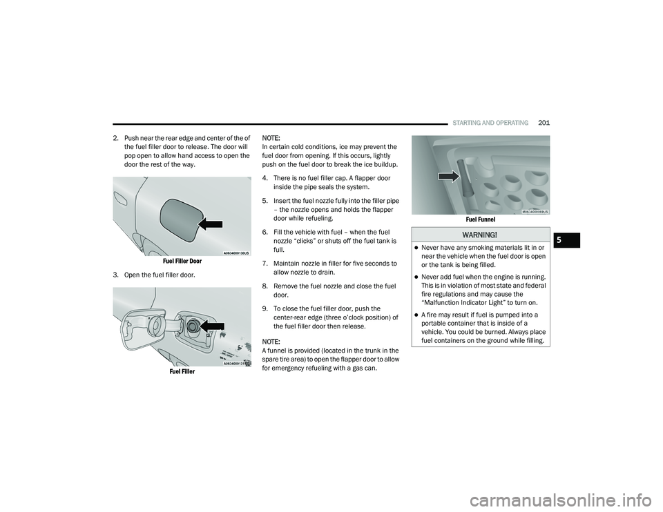
2. Push near the rear edge and center of the of
the fuel filler door to release. The door will
pop open to allow hand access to open the
door the rest of the way.
Fuel Filler Door
3. Open the fuel filler door.
Fuel Filler
NOTE:
In certain cold conditions, ice may prevent the
fuel door from opening. If this occurs, lightly
push on the fuel door to break the ice buildup.
4. There is no fuel filler cap. A flapper door
inside the pipe seals the system.
5. Insert the fuel nozzle fully into the filler pipe – the nozzle opens and holds the flapper
door while refueling.
6. Fill the vehicle with fuel – when the fuel nozzle “clicks” or shuts off the fuel tank is
full.
7. Maintain nozzle in filler for five seconds to allow nozzle to drain.
8. Remove the fuel nozzle and close the fuel door.
9. To close the fuel filler door, push the center-rear edge (three o’clock position) of
the fuel filler door then release.
NOTE:
A funnel is provided (located in the trunk in the
spare tire area) to open the flapper door to allow
for emergency refueling with a gas can.
Fuel Funnel
WARNING!
Never have any smoking materials lit in or
near the vehicle when the fuel door is open
or the tank is being filled.
Never add fuel when the engine is running.
This is in violation of most state and federal
fire regulations and may cause the
“Malfunction Indicator Light” to turn on.
A fire may result if fuel is pumped into a
portable container that is inside of a
vehicle. You could be burned. Always place
fuel containers on the ground while filling.
5
20_LD_OM_EN_USC_t.book Page 201
Page 209 of 412

STARTING AND OPERATING207
(Continued)
Perform the maintenance listed in the
“Scheduled Servicing”. Refer to “Scheduled
Servicing” in “Servicing And Maintenance” for
the proper maintenance intervals. When towing
a trailer, never exceed the GAWR or GCWR
ratings.
Towing Requirements — Tires
Do not attempt to tow a trailer while using a
compact spare tire.
Do not drive more than 50 mph (80 km/h) when towing while using a full size spare tire.
Proper tire inflation pressures are essential
to the safe and satisfactory operation of your
vehicle. Refer to “Tires” in “Servicing And
Maintenance” for proper tire inflation proce -
dures.
Check the trailer tires for proper tire inflation
pressures before trailer usage.
Check for signs of tire wear or visible tire
damage before towing a trailer. Refer to
“Tires” in “Servicing And Maintenance” for
the proper inspection procedure.
When replacing tires, refer to “Tires” in
“Servicing And Maintenance” for the proper
tire replacement procedures. Replacing tires
with a higher load carrying capacity will not
increase the vehicle's GVWR and GAWR
limits.
Towing Requirements — Trailer Brakes
Do not interconnect the hydraulic brake
system or vacuum system of your vehicle
with that of the trailer. This could cause inad -
equate braking and possible personal injury.
An electronically actuated trailer brake
controller is required when towing a trailer
with electronically actuated brakes. When
towing a trailer equipped with a hydraulic
surge actuated brake system, an electronic
brake controller is not required.
Trailer brakes are recommended for trailers
over 1,000 lbs (453 kg) and required for
trailers in excess of 2,000 lbs (907 kg).
GCWR must not be exceeded.
Total weight must be distributed between
the tow vehicle and the trailer such that the
following four ratings are not exceeded :
Max loading as defined on the “Tire and
Loading Information” placard.
GTW
GAWR
Tongue weight rating for the trailer
hitch utilized.
CAUTION!
Do not tow a trailer at all during the first
500 miles (805 km) the new vehicle is
driven. The engine, axle or other parts could
be damaged.
WARNING! (Continued)
Then, during the first 500 miles (805 km)
that a trailer is towed, do not drive over
50 mph (80 km/h) and do not make starts
at full throttle. This helps the engine and
other parts of the vehicle wear in at the
heavier loads.
CAUTION! (Continued)
5
20_LD_OM_EN_USC_t.book Page 207
Page 227 of 412

IN CASE OF EMERGENCY225
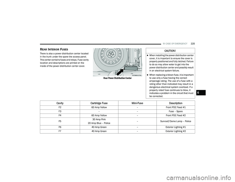
REAR INTERIOR FUSES
There is also a power distribution center located
in the trunk under the spare tire access panel.
This center contains fuses and relays. Fuse cavity
location and descriptions are printed on the
inside of the power distribution center cover.
Rear Power Distribution Center
CAUTION!
When installing the power distribution center
cover, it is important to ensure the cover is
properly positioned and fully latched. Failure
to do so may allow water to get into the
power distribution center and possibly result
in an electrical system failure.
When replacing a blown fuse, it is important
to use only a fuse having the correct
amperage rating. The use of a fuse with a
rating other than indicated may result in a
dangerous electrical system overload. If a
properly rated fuse continues to blow, it
indicates a problem in the circuit that must
be corrected.
CavityCartridge Fuse Mini-FuseDescription
F260 Amp Yellow –Front PDC Feed #1
F3 ––Fuse – Spare
F4 60 Amp Yellow –Front PDC Feed #2
F5 30 Amp Pink
20 Amp Blue – Police –
Sunroof/Dome Lamp – Police
F6 40 Amp Green –Exterior Lighting #1
F7 40 Amp Green –Exterior Lighting #2
6
20_LD_OM_EN_USC_t.book Page 225