2020 DODGE CHARGER tow bar
[x] Cancel search: tow barPage 56 of 412

54GETTING TO KNOW YOUR VEHICLE
Recirculation Button
Press and release this button to change the system between recirculation mode and outside air mode. The Recirculation
indicator and the A/C indicator illuminate when the Recirculation button is pressed. Recirculation can be used when
outside conditions such as smoke, odors, dust, or high humidity are present. Recirculation can be used in all modes except
for Defrost. Recirculation may be unavailable (button on the touchscreen greyed out) if conditions exist that could create
fogging on the inside of the windshield. The A/C can be deselected manually without disturbing the mode control selection.
Continuous use of the Recirculation mode may make the inside air stuffy and window fogging may occur. Extended use of
this mode is not recommended.
Front Defrost Button
Press and release the Front Defrost button on the touchscreen, or push and release the button on the faceplate, to change
the current airflow setting to Defrost mode. The Front Defrost indicator illuminates when Front Defrost is on. Air comes from
the windshield and side window demist outlets. When the defrost button is selected, the blower level may increase. Use
Defrost mode with maximum temperature settings for best windshield and side window defrosting and defogging. When
toggling the front defrost mode button, the climate system will return to the previous setting.
Rear Defrost Button
Press and release the Rear Defrost button on the touchscreen, or push and release the button on the faceplate, to turn on
the rear window defroster and the heated outside mirrors (if equipped). The Rear Defrost indicator illuminates when the
rear window defroster is on. The rear window defroster automatically turns off after 10 minutes.
Driver And Passenger Temperature Up And Down Buttons
Provides the driver and passenger with independent temperature control. Push the red button on the faceplate or
touchscreen or press and slide the temperature bar towards the red arrow button on the touchscreen for warmer
temperature settings. Push the blue button on the faceplate or touchscreen or press and slide the temperature bar towards
the blue arrow on the touchscreen for cooler temperature settings.
Icon Description
20_LD_OM_EN_USC_t.book Page 54
Page 61 of 412

GETTING TO KNOW YOUR VEHICLE59
Driver And Passenger Temperature Up And Down Buttons
Provides the driver and passenger with independent temperature control. Push the red button on the faceplate or
touchscreen or press and slide the temperature bar towards the red arrow button on the touchscreen for warmer
temperature settings. Push the blue button on the faceplate or touchscreen or press and slide the temperature bar towards
the blue arrow on the touchscreen for cooler temperature settings.
SYNC Button
Press the SYNC button on the touchscreen to toggle the Sync feature on/off. The SYNC indicator illuminates when SYNC is
on. SYNC synchronizes the passenger temperature setting with the driver temperature setting. Changing the passenger
temperature setting while in Sync will automatically exit this feature.
NOTE:
The SYNC button is only available on the touchscreen.
Faceplate Knob
Touchscreen Buttons Blower Control
Blower Control regulates the amount of air forced through the climate system. There are seven blower speeds available.
The speeds can be selected using either the blower control knob on the faceplate or the buttons on the touchscreen.
Faceplate: The blower speed increases as you turn the blower control knob clockwise from the lowest blower setting. The
blower speed decreases as you turn the blower control knob counterclockwise.
Touchscreen:
Use the small blower icon to reduce the blower setting and the large blower icon to increase the blower
setting. Blower can also be selected by pressing the blower bar area between the icons.
Icon Description
2
20_LD_OM_EN_USC_t.book Page 59
Page 151 of 412

SAFETY149
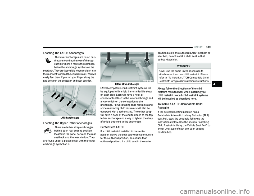
Locating The LATCH Anchorages
The lower anchorages are round bars
that are found at the rear of the seat
cushion where it meets the seatback,
below the anchorage symbols on the
seatback. They are just visible when you lean into
the rear seat to install the child restraint. You will
easily feel them if you run your finger along the
gap between the seatback and seat cushion.
LATCH Anchorages
Locating The Upper Tether Anchorages
There are tether strap anchorages
behind each rear seating position
located in the panel between the rear
seatback and the rear window. They
are found under a plastic cover with the tether
anchorage symbol on it.
Tether Strap Anchorages
LATCH-compatible child restraint systems will
be equipped with a rigid bar or a flexible strap
on each side. Each will have a hook or
connector to attach to the lower anchorage and
a way to tighten the connection to the
anchorage. Forward-facing child restraints and
some rear-facing child restraints will also be
equipped with a tether strap. The tether strap
will have a hook at the end to attach to the top
tether anchorage and a way to tighten the strap
after it is attached to the anchorage.Center Seat LATCH
If a child restraint installed in the center
position blocks the seat belt webbing or buckle
for the outboard position, do not use that
outboard position. If a child seat in the center position blocks the outboard LATCH anchors or
seat belt, do not install a child seat in that
outboard position.
Always follow the directions of the child
restraint manufacturer when installing your
child restraint. Not all child restraint systems
will be installed as described here.
To Install A LATCH-Compatible Child
Restraint
If the selected seating position has a
Switchable Automatic Locking Retractor (ALR)
seat belt, stow the seat belt, following the
instructions below. See the section “Installing
Child Restraints Using the Vehicle Seat Belt” to
check what type of seat belt each seating
position has.
WARNING!
Never use the same lower anchorage to
attach more than one child restraint. Please
refer to “To Install A LATCH-Compatible Child
Restraint” for typical installation instructions.
4
20_LD_OM_EN_USC_t.book Page 149
Page 206 of 412

204STARTING AND OPERATING
Tongue Weight (TW)
The tongue weight is the downward force
exerted on the hitch ball by the trailer. You must
consider this as part of the load on your vehicle.
Trailer Frontal Area
The frontal area is the maximum height multiplied
by the maximum width of the front of a trailer.
Trailer Sway Control
The Trailer Sway Control (TSC) can be a
mechanical telescoping link that can be
installed between the hitch receiver and the
trailer tongue that typically provides adjustable
friction associated with the telescoping motion
to dampen any unwanted trailer swaying
motions while traveling. If equipped, the electronic TSC recognizes a
swaying trailer and automatically applies
individual wheel brakes and/or reduces engine
power to attempt to eliminate the trailer sway.
Weight-Carrying Hitch
A weight-carrying hitch supports the trailer
tongue weight, just as if it were luggage located
at a hitch ball or some other connecting point of
the vehicle. These kinds of hitches are the most
popular on the market today and they are
commonly used to tow small and medium sized
trailers.
Weight-Distributing Hitch
A weight-distributing system works by applying
leverage through spring (load) bars. They are
typically used for heavier loads to distribute
trailer tongue weight to the tow vehicle's front
axle and the trailer axle(s). When used in
accordance with the manufacturer's directions,
it provides for a more level ride, offering more
consistent steering and brake control thereby
enhancing towing safety. The addition of a
friction/hydraulic sway control also dampens
sway caused by traffic and crosswinds and
contributes positively to tow vehicle and trailer
stability. Trailer sway control and a weight
distributing (load equalizing) hitch are
recommended for heavier Tongue Weights (TW)
and may be required depending on vehicle and
trailer configuration/loading to comply with
Gross Axle Weight Rating (GAWR) requirements.
WARNING!
It is important that you do not exceed the
maximum front or rear GAWR. A dangerous
driving condition can result if either rating is
exceeded. You could lose control of the
vehicle and have a collision.
WARNING!
An improperly adjusted Weight Distributing
Hitch system may reduce handling,
stability, braking performance, and could
result in a collision.
Weight Distributing Systems may not be
compatible with Surge Brake Couplers.
Consult with your hitch and trailer manufac
-
turer or a reputable Recreational Vehicle
dealer for additional information.
20_LD_OM_EN_USC_t.book Page 204
Page 248 of 412

246IN CASE OF EMERGENCY
SRT — TOWING A DISABLED VEHICLE
This section describes procedures for towing a disabled vehicle using a commercial towing service.
Proper towing or lifting equipment is required to
prevent damage to your vehicle. Use only tow
bars and other equipment designed for this
purpose, following equipment manufacturer’s
instructions. Use of safety chains is mandatory.
Attach a tow bar or other towing device to main
structural members of the vehicle, not to
bumpers or associated brackets. State and
local laws regarding vehicles under tow must be
observed. If you must use the accessories (wipers,
defrosters, etc.) while being towed, the ignition
must be in the ON/RUN mode, not the ACC
mode.
If the key fob is unavailable, or the vehicle's
battery is discharged, refer to "Manual Park
Release" in this section for instructions on
shifting the transmission out of PARK for
towing.
Towing Condition
Wheels OFF The GroundAutomatic Transmission
Flat Tow NONEIf transmission is operable:
• Transmission in
NEUTRAL
• 30 mph (48 km/h) max speed
• 30 miles (48 km) max distance
Wheel Lift Or Dolly Tow Front
NOT ALLOWED
Rear NOT RECOMMENDED
Flatbed ALLBEST METHOD
CAUTION!
DO NOT use sling-type equipment when
towing. Vehicle damage may occur.
When securing the vehicle to a flatbed
truck, do not attach to front or rear suspen-
sion components. Damage to your vehicle
may result from improper towing.
The manufacturer does not recommend
towing this vehicle using a tow dolly.
Vehicle damage may occur.
20_LD_OM_EN_USC_t.book Page 246
Page 250 of 412

248IN CASE OF EMERGENCY
(Continued)
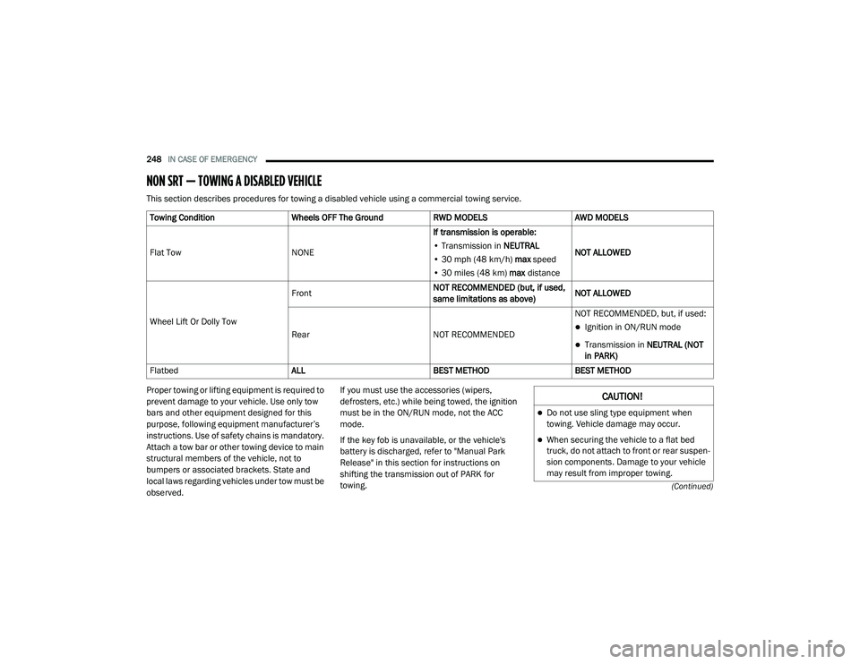
NON SRT — TOWING A DISABLED VEHICLE
This section describes procedures for towing a disabled vehicle using a commercial towing service.
Proper towing or lifting equipment is required to
prevent damage to your vehicle. Use only tow
bars and other equipment designed for this
purpose, following equipment manufacturer’s
instructions. Use of safety chains is mandatory.
Attach a tow bar or other towing device to main
structural members of the vehicle, not to
bumpers or associated brackets. State and
local laws regarding vehicles under tow must be
observed.If you must use the accessories (wipers,
defrosters, etc.) while being towed, the ignition
must be in the ON/RUN mode, not the ACC
mode.
If the key fob is unavailable, or the vehicle's
battery is discharged, refer to "Manual Park
Release" in this section for instructions on
shifting the transmission out of PARK for
towing.
Towing Condition
Wheels OFF The GroundRWD MODELSAWD MODELS
Flat Tow NONEIf transmission is operable:
• Transmission in NEUTRAL
• 30 mph (48 km/h) max speed
• 30 miles (48 km) max distance NOT ALLOWED
Wheel Lift Or Dolly Tow Front
NOT RECOMMENDED (but, if used,
same limitations as above)NOT ALLOWED
Rear NOT RECOMMENDEDNOT RECOMMENDED, but, if used:
Ignition in ON/RUN mode
Transmission in
NEUTRAL (NOT
in PARK)
Flatbed ALLBEST METHODBEST METHOD
CAUTION!
Do not use sling type equipment when
towing. Vehicle damage may occur.
When securing the vehicle to a flat bed
truck, do not attach to front or rear suspen -
sion components. Damage to your vehicle
may result from improper towing.
20_LD_OM_EN_USC_t.book Page 248
Page 403 of 412

401
Power Brakes
....................................................... 308Deck Lid Release........................................ 68Distribution Center (Fuses)....................... 225Door Locks.................................................. 26Mirrors......................................................... 43Outlet (Auxiliary Electrical Outlet)................ 78Seats........................................................... 34Steering..................................................... 174Sunroof....................................................... 66Tilt/Telescoping Steering Column............... 40Windows...................................................... 64Power SeatsForward....................................................... 34Lumbar........................................................ 35Rearward..................................................... 34Recline........................................................ 35Power Steering Fluid................... 315, 318, 320Pregnant Women And Seat Belts...................132Preparation For Jacking................................. 230PretensionersSeat Belts.................................................. 132Programmable Features................................ 322
R
Radial Ply Tires.............................................. 295Radiator Cap (Coolant Pressure Cap)............ 282RadioPresets...................................................... 357
Radio Operation................................... 356, 383Rain Sensitive Wiper System........................... 52Rear Axle (Differential).................................. 286Rear Camera................................................. 199Rear Cross Path............................................ 116Rear ParkSense System............................... 191Rear Seats, Folding.......................................... 33Rear Wheel Drive (RWD)Towing...................................................... 249Recreational Towing..................................... 210Reformulated Gasoline................................. 310Refrigerant.................................................... 275Release, Hood................................................. 68Reminder, Lights On........................................ 47Reminder, Seat Belt...................................... 126Remote Keyless EntryArm The Alarm............................................. 24Panic Alarm................................................. 15Programming Additional Key Fobs........ 17, 23Unlatch The Trunk....................................... 14Remote StartingExit Remote Start Mode.............................. 21Uconnect Customer Programmable Features.........................................21, 332Uconnect Settings..............................21, 332Remote Trunk Release.................................... 68Replacement Bulbs...................................... 217Replacement Keys.................................... 17, 23
Replacement Tires........................................ 297Reporting Safety Defects.............................. 393Restraints, Child............................................ 143Restraints, Head.......................................38, 39Rocking Vehicle When Stuck......................... 244Rotation, Tires...................................... 302, 303
S
Safety Checks Inside Vehicle........................ 156Safety Checks Outside Vehicle...................... 157Safety Defects, Reporting............................. 393Safety Information, Tire................................. 286Safety Tips.................................................... 155Safety, Exhaust Gas...................................... 155Schedule, Maintenance....................... 250, 254Seat Belt Reminder..........................................97Seat Belts............................................ 126, 156Adjustable Shoulder Belt.......................... 130Adjustable Upper Shoulder Anchorage..... 130
Adjustable Upper Shoulder Belt Anchorage.. 130
Automatic Locking Retractor (ALR)........... 132Child Restraints........................................ 143Energy Management Feature................... 132Extender................................................... 131Front Seat............................... 126, 127, 129Inspection................................................. 156Lap/Shoulder Belt Operation.................... 129Lap/Shoulder Belt Untwisting................... 130Lap/Shoulder Belts................................... 127
11
20_LD_OM_EN_USC_t.book Page 401