2020 CITROEN RELAY tow bar
[x] Cancel search: tow barPage 112 of 196

11 0
In the event of a breakdown
► Lightly tighten using wheelbrace D and wheel
bar B.
► Lower the vehicle using wheelbrace D and
wheel bar B, and then remove the jack.
► Tighten the bolts again using wheelbrace D
and wheel bar B.
Have the tightening of the bolts and the
pressure of the spare wheel checked by
the Manufacturer's dealer network or a
qualified workshop without delay.
Have the punctured wheel repaired and
refitted on the vehicle as soon as possible.
If your vehicle has tyre under-inflation
detection, check the tyre pressures and
reinitialise the system.
5 - Storing the wheel to be
repaired
You must reposition the wheel to be repaired or
the spare wheel under the vehicle to lock the
winch system.
Check that it is securely fastened in its
compartment under the floor.
Improper wheel positioning can compromise
safety.
► Reposition the wheel at the rear of the
vehicle.
With steel wheels:
► Hang bracket I on the outer part.
► Screw handle H to secure the bracket and
the steel wheel.
With alloy wheels:
► Position bracket J on caliper I.
► Screw handle H.
► Screw the three fixing bolts K of caliper I onto
the alloy wheel.
► Install extended socket A, wheelbrace D and
wheel bar B on the retaining bolt.
► Turn the assembly clockwise to completely
wind up the cable and raise the wheel as far as
possible under the vehicle.
► Check that the wheel is flat against the floor
of the vehicle and that the notch G of the winch
is visible.
► Store the tools and the wheel trim (depending
on version).
For more information on
the Identification markings of the
vehicle, and in particular the tyre pressure
label, refer to the corresponding section.
Changing a bulb
The headlamps have polycarbonate lenses with a protective coating:
► do not clean them using a dry or
abrasive cloth, nor with a detergent or
solvent product,
► use a sponge and soapy water or a pH
neutral product,
► when using a high pressure washer on
persistent marks, do not keep the lance
directed towards the lamps or their edges for
too long, so as not to damage their protective
coating and seals.
Changing a bulb must only be done with
the ignition off and after the lamp has
been switched off for several minutes - Risk
of serious burns!
► Do not touch the bulb directly with your
fingers, use a lint-free cloth.
It is essential only to use anti-ultraviolet
(UV) type bulbs, so as not to damage the
headlamp.
Always replace a failed bulb with a new bulb
with the same type and specification.
In some weather conditions (e.g. low
temperature or humidity), the presence
of misting on the internal surface of the glass
of the headlamps and rear lamps is normal; it
Page 124 of 196

122
In the event of a breakdown
► Connect the red cable to metallic terminal A,
then to the (+) terminal of backup battery B.
► Connect one end of the green or black cable
to the negative (-) terminal of backup battery B.
► Connect the other end of the green or black
cable to earth point C of your vehicle.
► Operate the starter, let the engine run.
► Wait for the engine to return to idle and
disconnect the cables.
Charging the battery using a
battery charger
► Access the battery, located in the left-hand
front floor.
► Disconnect the battery.
► Follow the instructions for use provided by
the manufacturer of the charger.
► Reconnect starting with the (-) terminal.
► Check the cleanliness of the terminals. If they
are covered with sulphate (whitish or greenish
deposit), remove and clean them.
The charging operation must be carried out in a well-ventilated area and away
from naked flames and any sources of sparks
so as to avoid the risk of explosion or fire.
Do not try to recharge a frozen battery: it
must first be thawed to avoid the risk of
explosion. If it has frozen, before charging it,
have the battery checked by a specialist who
will check that the interior components have
not been damaged and that the container is
not cracked, which would involve a risk of
leakage of toxic and corrosive acid.
Perform a slow charge at low amperage for
about 24 hours maximum to avoid damaging
the battery.
The presence of this label, in particular with the Stop & Start system, indicates
the use of a 12 V lead-acid battery with
special technology and specification; the
involvement of a CITROËN dealer or a
qualified workshop is essential when
replacing or disconnecting the battery.
After refitting the battery at a CITROËN dealer or a qualified workshop, the Stop
& Start system will only be active after a
continuous period of immobilisation of the
vehicle, a period which depends on the
climatic conditions and the state of charge of
the battery (up to about 8 hours).
Towing
General recommendations
Observe the legislation in force in the
country where you are driving.
Ensure that the weight of the towing vehicle is
higher than that of the towed vehicle.
The driver must remain at the wheel of the
towed vehicle and must have a valid driving
licence.
When towing a vehicle with all four wheels on
the ground, always use an approved towing
arm; rope and straps are prohibited.
The towing vehicle must move off gently.
When the vehicle is towed with its engine
off, there is no longer braking and steering
assistance.
A professional towing service must be
called if:
– Broken down on a motorway or main road.
– Not possible to put the gearbox into neutral,
unlock the steering, or release the parking
brake.
– Not possible to tow a vehicle with an
automatic gearbox, with the engine running.
– Towing with only two wheels on the ground.
– Four-wheel drive vehicle.
– No approved towbar available.
Towing your vehicle
The removable towing eye is located in the tool
box under the front passenger seat.
► Unclip the cover using a flat tool.
► Screw the removable towing eye in fully.
► Attach the approved towbar to the removable
towing eye.
► Place the gear lever in neutral.
Page 125 of 196

123
In the event of a breakdown
8Towing constraints
Type of vehicle
(engine / gearbox)gearbox Font wheels on the
ground Rear wheels on the
ground Flatbed
4 wheels on the ground
with towbar
Internal combustion /
Manual
Towing your vehicle
The removable towing eye is located in the tool
box under the front passenger seat.
► Unclip the cover using a flat tool.
► Screw the removable towing eye in fully.
► Attach the approved towbar to the removable
towing eye.
► Place the gear lever in neutral.
Failure to adhere to this instruction may
lead to damage to braking system
components and the lack of braking
assistance on restarting the engine.
Towing another vehicle
The fixed towing eye is located under the
bumper, on the right-hand side.
► Attach the approved towbar to the rigid eye.
Page 148 of 196

146
Special features
Specifications
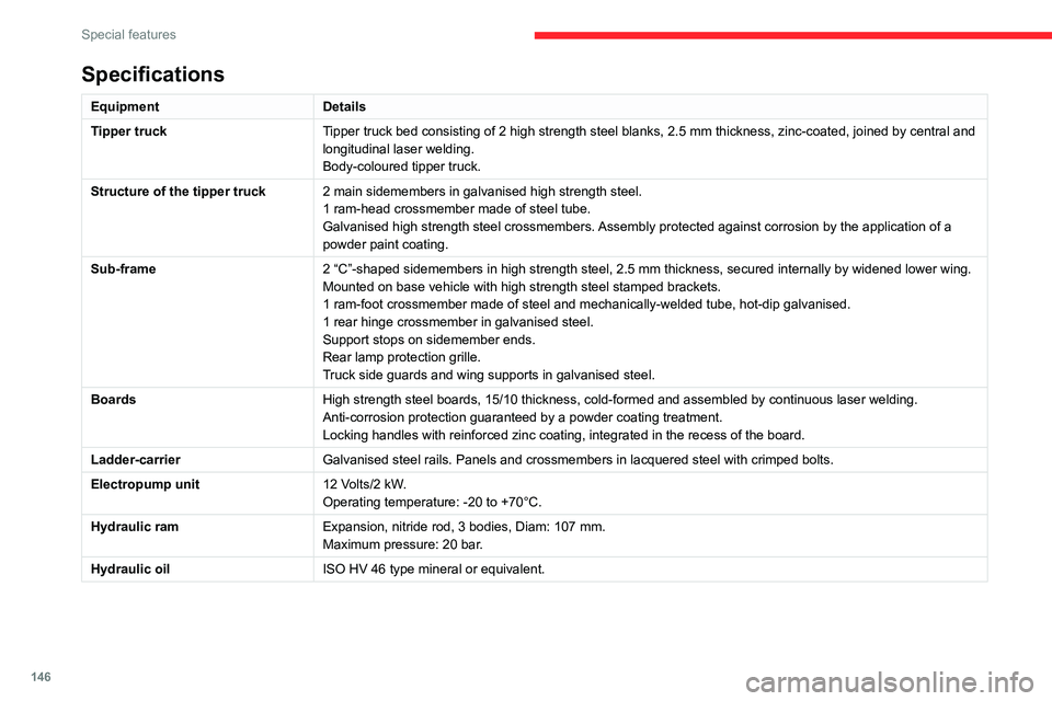
EquipmentDetails
Tipper truck Tipper truck bed consisting of 2 high strength steel blanks, 2.5 mm thickness, zinc-coated, joined by central and
longitudinal laser welding.
Body-coloured tipper truck.
Structure of the tipper truck 2 main sidemembers in galvanised high strength steel.
1 ram-head crossmember made of steel tube.
Galvanised high strength steel crossmembers. Assembly protected against corrosion by the application of a
powder paint coating.
Sub-frame 2 “C”-shaped sidemembers in high strength steel, 2.5 mm thickness, secured internally by widened lower wing.
Mounted on base vehicle with high strength steel stamped brackets.
1 ram-foot crossmember made of steel and mechanically-welded tube, hot-dip galvanised.
1 rear hinge crossmember in galvanised steel.
Support stops on sidemember ends.
Rear lamp protection grille.
Truck side guards and wing supports in galvanised steel.
Boards High strength steel boards, 15/10 thickness, cold-formed and assembled by continuous laser welding.
Anti-corrosion protection guaranteed by a powder coating treatment.
Locking handles with reinforced zinc coating, integrated in the recess of the board.
Ladder-carrier Galvanised steel rails. Panels and crossmembers in lacquered steel with crimped bolts.
Electropump unit 12 Volts/2 kW.
Operating temperature: -20 to +70°C.
Hydraulic ram Expansion, nitride rod, 3 bodies, Diam: 107 mm.
Maximum pressure: 20 bar.
Hydraulic oil ISO HV 46 type mineral or equivalent.
Dimensions
This adaptation is available only on L2 single
cab; refer to the table below for the specifications
of the tipper truck.
Tipper truck (in mm)
Useable length 3,200
Overall length 3,248
Useable width 2,000
Overall width 2,100
Height of boards 350
Weight of the conversion (in
kg) 550
For the L2 chassis cab specifications,
refer to the Dimensions section of the
platform version.
Weights and towed loads
(kg)
The braked trailer weight with load transfer can
be increased, provided that the equivalent of this
load is removed from the vehicle so as not to
exceed the GTW. Warning! Towing using a lightly
loaded vehicle can adversely affect roadholding.
The kerb weight is equal to the unladen weight +
driver (75 kg) + tank full to 90%.
Page 181 of 196

179
Alphabetical index
Tools 105–110
Topping-up AdBlue® 102
Touch screen 158, 173
Touch screen audio-telematic system 158, 173
Towball, quickly detachable 92–94
Towbar with quickly detachable towball 92–94
Towed loads 124
Towing another vehicle 122
Traction control (ASR) 52–53
Traffic information (TA) 152
Trip computer 19
Type of bulbs 111
Tyres 100
Tyre under-inflation detection 71–72
U
Under-inflation (detection) 71–72
USB 152–153, 161–162
V
Ventilation 31–33
Voice commands 155–157, 169–171
W
Warning and indicator lamps 6–7
Warning lamps 7
Warning lamp, seat belts 55
Warnings and indicators 6–7
Washing 74
Weights 124
Wheel, spare 100, 105–110
Window controls 25
Wipers 49
Wipers, automatic rain sensitive 49