2020 CHRYSLER 300 instrument panel
[x] Cancel search: instrument panelPage 52 of 328

50GETTING TO KNOW YOUR VEHICLE
desires less wiper sensitivity. Setting 4 can be
used if the driver desires more sensitivity. The
rain sensing wipers will automatically change
between an intermittent wipe, slow wipe and a
fast wipe depending on the amount of moisture
that is sensed on the windshield. Place the
wiper switch in the OFF position when not using
the system.
The Rain Sensing feature can be turned on and
off using the Uconnect system, refer to
“Uconnect Settings” in “Multimedia” for further
information.
NOTE:
The Rain Sensing feature will not operate
when the wiper speed is in the low or high
position.
The Rain Sensing feature may not function
properly when ice or dried salt water is
present on the windshield.
Use of Rain-X or products containing wax or
silicone may reduce rain sensor perfor -
mance. The Rain Sensing system has protective
features for the wiper blades and arms. It will
not operate under the following conditions:
Low Temperature Wipe Inhibit
— The Rain
Sensing feature will not operate when the
ignition is placed in the ON/RUN position, the
vehicle is stationary and the outside
temperature is below 32°F (0°C), unless the
wiper control on the multifunction lever is
moved, the vehicle speed becomes greater
than 0 mph (0 km/h) or the outside tempera -
ture rises above freezing.
Neutral Wipe Inhibit — The Rain Sensing
feature will not operate when the ignition is
placed in the ON/RUN position, the auto -
matic transmission gear selector is in the
NEUTRAL position and the vehicle speed is
less than 3 mph (5 km/h), unless the wiper
control on the multifunction lever is moved or
the gear selector is moved out of the
NEUTRAL position.
Remote Start Mode Inhibit — On vehicles
equipped with Remote Starting system, Rain
Sensing wipers are not operational when the
vehicle is in the remote start mode. Once the
operator is in the vehicle and has placed the ignition switch in the ON/RUN position, rain
sensing wiper operation can resume, if it has
been selected, and no other inhibit condi
-
tions (mentioned previously) exist.
CLIMATE CONTROLS
The Climate Control system allows you to
regulate the temperature, air flow, and direction
of air circulating throughout the vehicle. The
controls are located on the touchscreen (if
equipped) and on the instrument panel below
the radio.
AUTOMATIC CLIMATE CONTROL
O
VERVIEW
Uconnect 4C/4C NAV Automatic Climate Controls
20_LX_OM_EN_USC_t.book Page 50
Page 55 of 328

GETTING TO KNOW YOUR VEHICLE53
Faceplate Knob
Touchscreen Buttons Blower Control
Blower Control regulates the amount of air forced through the climate system. There are seven blower speeds available.
The speeds can be selected using either the blower control knob on the faceplate or the buttons on the touchscreen.
Faceplate: The blower speed increases as you turn the blower control knob clockwise from the lowest blower setting.
The blower speed decreases as you turn the blower control knob counterclockwise.
Touchscreen:
Use the small blower icon to reduce the blower setting and the large blower icon to increase the blower
setting. Blower can also be selected by pressing the blower bar area between the icons.
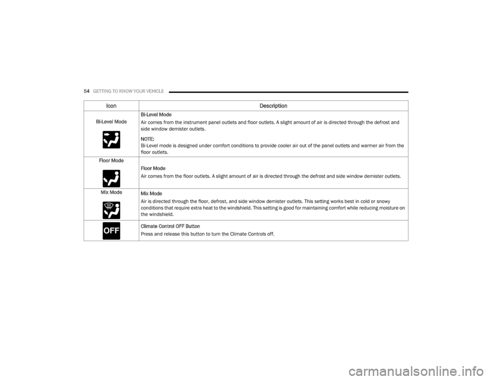
Mode Control
Select Mode by pressing one of the Mode buttons on the touchscreen to change the airflow distribution mode. The airflow
distribution mode can be adjusted so air comes from the instrument panel outlets, floor outlets, defrost outlets and demist
outlets.
The Mode settings are as follows:
Panel Mode Panel Mode
Air comes from the outlets in the instrument panel. Each of these outlets can be individually adjusted to direct the flow of
air. The air vanes of the center outlets and outboard outlets can be moved up and down or side to side to regulate airflow
direction. There is a shut off wheel located below the air vanes to shut off or adjust the amount of airflow from these
outlets.
Icon
Description
2
20_LX_OM_EN_USC_t.book Page 53
Page 56 of 328

54GETTING TO KNOW YOUR VEHICLE
Bi-Level ModeBi-Level Mode
Air comes from the instrument panel outlets and floor outlets. A slight amount of air is directed through the defrost and
side window demister outlets.
NOTE:
Bi-Level mode is designed under comfort conditions to provide cooler air out of the panel outlets and warmer air from the
floor outlets.
Floor Mode Floor Mode
Air comes from the floor outlets. A slight amount of air is directed through the defrost and side window demister outlets.
Mix Mode Mix Mode
Air is directed through the floor, defrost, and side window demister outlets. This setting works best in cold or snowy
conditions that require extra heat to the windshield. This setting is good for maintaining comfort while reducing moisture on
the windshield.
Climate Control OFF Button
Press and release this button to turn the Climate Controls off.
Icon Description
20_LX_OM_EN_USC_t.book Page 54
Page 63 of 328

GETTING TO KNOW YOUR VEHICLE61
CLOSING POWER SHADE
Express Mode
Push the switch forward and release it within
one-half second and the shade will close
automatically from any position. If the sunroof is
completely closed the shade will close fully and
stop automatically. This is called “Express
Close”. During Express Close operation, any
movement of the switch will stop the shade.
NOTE:
If the sunroof is open, the shade will close to the
half-open position. Pushing the shade close
button again will automatically close both the
sunroof and shade completely.
Manual Mode
To close the shade, push and hold the switch in
the forward position. Any release of the switch
will stop the movement and the shade will
remain in a partially closed condition until the
switch is pushed again.
PINCH PROTECT FEATURE
This feature will detect an obstruction in the
closing of the sunroof during the Express Close
operation. If an obstruction in the path of the sunroof is detected, the sunroof will
automatically retract. Remove the obstruction if
this occurs.
NOTE:
If three consecutive sunroof close attempts
result in Pinch Protect reversals, Pinch Protect
will disable and the sunroof must be closed in
Manual Mode.
SUNROOF MAINTENANCE
Use only a non-abrasive cleaner and a soft cloth
to clean the glass panel. Periodically check for
and clear out any debris that may have
collected in the tracks.
IGNITION OFF OPERATION
NOTE:
The power sunroof switch can remain active
in Accessory Delay for up to approximately
10 minutes after the vehicle’s ignition is
placed in the OFF position. Opening either
front door will cancel this feature.
This feature is programmable using the
Uconnect system. Refer to “Uconnect
Settings” in “Multimedia” for further informa
-
tion.
HOOD
TO OPEN THE HOOD
Two latches must be released to open the hood.
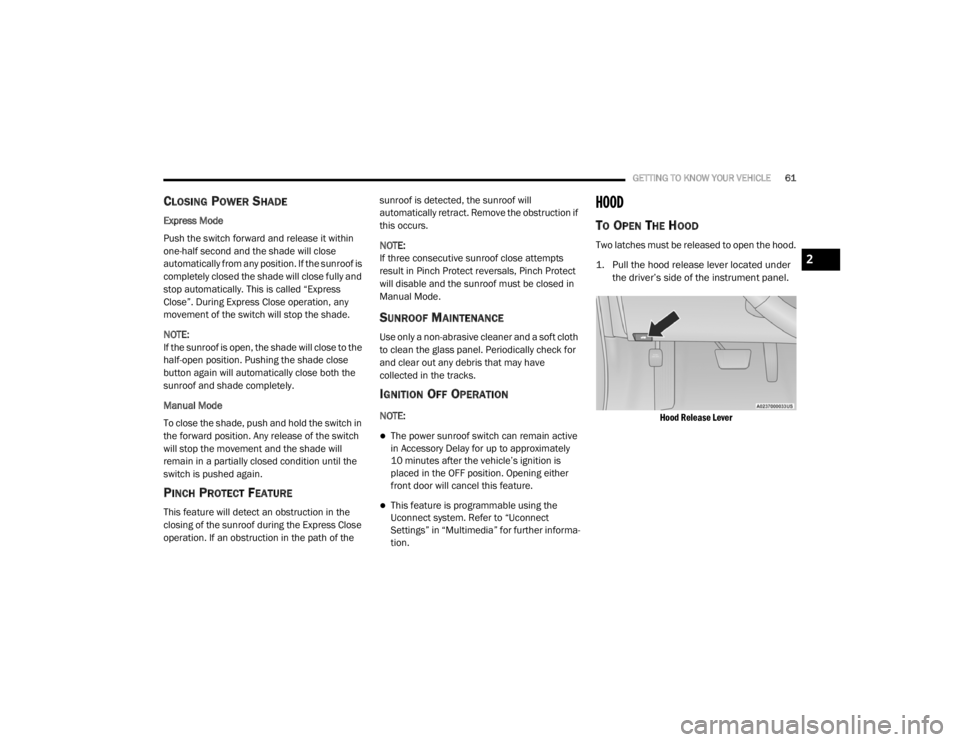
1. Pull the hood release lever located under
the driver’s side of the instrument panel.
Hood Release Lever
2
20_LX_OM_EN_USC_t.book Page 61
Page 64 of 328

62GETTING TO KNOW YOUR VEHICLE
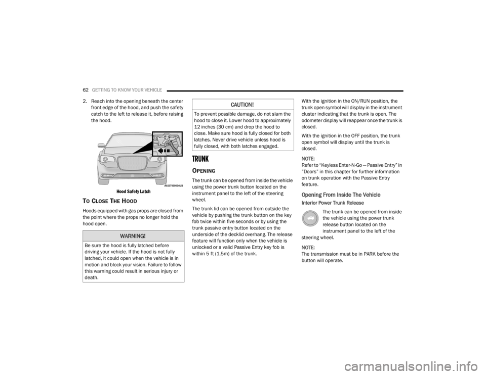
2. Reach into the opening beneath the center
front edge of the hood, and push the safety
catch to the left to release it, before raising
the hood.
Hood Safety Latch
TO CLOSE THE HOOD
Hoods equipped with gas props are closed from
the point where the props no longer hold the
hood open.
TRUNK
OPENING
The trunk can be opened from inside the vehicle
using the power trunk button located on the
instrument panel to the left of the steering
wheel.
The trunk lid can be opened from outside the
vehicle by pushing the trunk button on the key
fob twice within five seconds or by using the
trunk passive entry button located on the
underside of the decklid overhang. The release
feature will function only when the vehicle is
unlocked or a valid Passive Entry key fob is
within 5 ft (1.5m) of the trunk. With the ignition in the ON/RUN position, the
trunk open symbol will display in the instrument
cluster indicating that the trunk is open. The
odometer display will reappear once the trunk is
closed.
With the ignition in the OFF position, the trunk
open symbol will display until the trunk is
closed.
NOTE:
Refer to “Keyless Enter-N-Go — Passive Entry” in
”Doors” in this chapter for further information
on trunk operation with the Passive Entry
feature.
Opening From Inside The Vehicle
Interior Power Trunk Release
The trunk can be opened from inside
the vehicle using the power trunk
release button located on the
instrument panel to the left of the
steering wheel.
NOTE:
The transmission must be in PARK before the
button will operate.
WARNING!
Be sure the hood is fully latched before
driving your vehicle. If the hood is not fully
latched, it could open when the vehicle is in
motion and block your vision. Failure to follow
this warning could result in serious injury or
death.
CAUTION!
To prevent possible damage, do not slam the
hood to close it. Lower hood to approximately
12 inches (30 cm) and drop the hood to
close. Make sure hood is fully closed for both
latches. Never drive vehicle unless hood is
fully closed, with both latches engaged.
20_LX_OM_EN_USC_t.book Page 62
Page 72 of 328

70GETTING TO KNOW YOUR VEHICLE
GENERAL INFORMATION
The following regulatory statement applies to all
Radio Frequency (RF) devices equipped in this
vehicle:
This device complies with Part 15 of the FCC
Rules and with Innovation, Science and
Economic Development Canada license-exempt
RSS standard(s). Operation is subject to the
following two conditions:
1. This device may not cause harmful
interference, and
2. This device must accept any interference received, including interference that may
cause undesired operation.
Le présent appareil est conforme aux CNR
d`Innovation, Science and Economic
Development applicables aux appareils radio
exempts de licence. L'exploitation est autorisée
aux deux conditions suivantes:
1. l'appareil ne doit pas produire de brouillage, et
2. l'utilisateur de l'appareil doit accepter tout brouillage radioélectrique subi, même si le brouillage est susceptible d'en compro
-
mettre le fonctionnement.
La operación de este equipo está sujeta a las
siguientes dos condiciones:
1. es posible que este equipo o dispositivo no cause interferencia perjudicial y
2. este equipo o dispositivo debe aceptar cualquier interferencia, incluyendo la que
pueda causar su operación no deseada.
NOTE:
Changes or modifications not expressly
approved by the party responsible for compli -
ance could void the user’s authority to operate
the equipment.
INTERNAL EQUIPMENT
STORAGE
Glove Compartment
The glove compartment is located on the
passenger side of the instrument panel.
To open the glove compartment, pull the
release handle.
Glove Compartment
Cubby Bin
There is a cubby bin located forward of the gear
selector. The cubby bin is covered with a
push-push actuated door. Push inward on the
door to open it; push the door a second time to
close it.
Cubby Bin
20_LX_OM_EN_USC_t.book Page 70
Page 76 of 328

74GETTING TO KNOW YOUR VEHICLE
ELECTRICAL POWER OUTLETS
Your vehicle is equipped with one 12 Volt
(13 Amp) power outlet on the instrument panel
and one 12 Volt (13 Amp) power outlet in the
center console that can be used to power
cellular phones, small electronics and other low
powered electrical accessories. The power
outlets are labeled with either a “key” or a
“battery” symbol to indicate how the outlet is
powered. Power outlets labeled with a “key” are
powered when the ignition switch is in the ACC
or ON/RUN position, while the outlets labeled
with a “battery” are connected directly to the
battery and powered at all times.
NOTE:
All accessories connected to the “battery”
powered outlets should be removed or turned
off when the vehicle is not in use to protect the
battery against discharge.
The front power outlet is located inside the
storage area on the center stack of the
instrument panel.
Front Power Outlet
In addition to the front power outlet, there is
also a power outlet located in the storage area
of the center console.
Center Console Power Outlet
NOTE:
If the Media Hub is in use, do not exceed the
maximum power of 100 Watts (8 Amps) for the
center console power outlet. When the Media
Hub is not in use, the outlet can deliver up to
120 Watts (10 Amps). If the power rating is
exceeded, the fuse protecting the system will
need to be replaced.
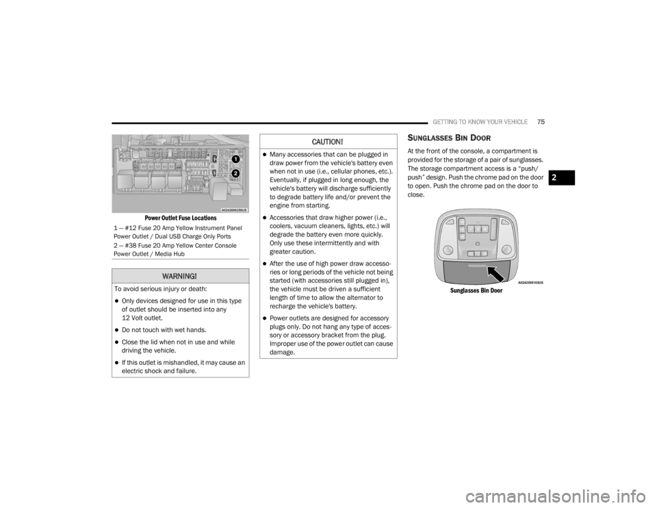
The instrument panel power outlet and dual
rear console USB ports can be changed to
“battery” (powered at all times) by moving the
#12 20 Amp fuse from “IGN” to “B+”. These
fuses are located in the fuse box in the trunk,
below the load floor.
WARNING!
Do not place ashes inside the cubby bin
located on the center console on vehicles not
equipped with the ash receiver tray. A fire
leading to bodily injury could result.
20_LX_OM_EN_USC_t.book Page 74
Page 77 of 328

GETTING TO KNOW YOUR VEHICLE75
Power Outlet Fuse Locations
SUNGLASSES BIN DOOR
At the front of the console, a compartment is
provided for the storage of a pair of sunglasses.
The storage compartment access is a “push/
push” design. Push the chrome pad on the door
to open. Push the chrome pad on the door to
close.
Sunglasses Bin Door
1 — #12 Fuse 20 Amp Yellow Instrument Panel
Power Outlet / Dual USB Charge Only Ports
2 — #38 Fuse 20 Amp Yellow Center Console
Power Outlet / Media Hub
WARNING!
To avoid serious injury or death:
Only devices designed for use in this type
of outlet should be inserted into any
12 Volt outlet.
Do not touch with wet hands.
Close the lid when not in use and while
driving the vehicle.
If this outlet is mishandled, it may cause an
electric shock and failure.
CAUTION!
Many accessories that can be plugged in
draw power from the vehicle's battery even
when not in use (i.e., cellular phones, etc.).
Eventually, if plugged in long enough, the
vehicle's battery will discharge sufficiently
to degrade battery life and/or prevent the
engine from starting.
Accessories that draw higher power (i.e.,
coolers, vacuum cleaners, lights, etc.) will
degrade the battery even more quickly.
Only use these intermittently and with
greater caution.
After the use of high power draw accesso -
ries or long periods of the vehicle not being
started (with accessories still plugged in),
the vehicle must be driven a sufficient
length of time to allow the alternator to
recharge the vehicle's battery.
Power outlets are designed for accessory
plugs only. Do not hang any type of acces -
sory or accessory bracket from the plug.
Improper use of the power outlet can cause
damage.
2
20_LX_OM_EN_USC_t.book Page 75