2020 CHRYSLER 300 flat tire
[x] Cancel search: flat tirePage 201 of 328

STARTING AND OPERATING199
Traction
When driving on wet or slushy roads, it is
possible for a wedge of water to build up
between the tire and road surface. This is
known as hydroplaning and may cause partial
or complete loss of vehicle control and stopping
ability. To reduce this possibility, the following
precautions should be observed:
Slow down during rainstorms or when the
roads are slushy.
Slow down if the road has standing water or
puddles.
Replace tires when tread wear indicators first
become visible.
Keep tires properly inflated.
Maintain sufficient distance between your
vehicle and the vehicle in front of you to avoid
a collision in a sudden stop.
Your vehicle may be equipped with a Limited
Slip Differential (LSD) that reduces, but does
not eliminate, the amount of wheel slip across a
given axle for improved handling.
DRIVING THROUGH WATER
Driving through water more than a few inches/
centimeters deep will require extra caution to
ensure safety and prevent damage to your
vehicle.
Flowing/Rising Water Shallow Standing Water
Although your vehicle is capable of driving
through shallow standing water, consider
the following Warnings and Cautions before
doing so.
WARNING!
Do not drive on or across a road or path
where water is flowing and/or rising (as in
storm run-off). Flowing water can wear away
the road or path's surface and cause your
vehicle to sink into deeper water.
Furthermore, flowing and/or rising water can
carry your vehicle away swiftly. Failure to
follow this warning may result in injuries that
are serious or fatal to you, your passengers,
and others around you.
WARNING!
Driving through standing water limits your
vehicle’s traction capabilities. Do not
exceed 5 mph (8 km/h) when driving
through standing water.
Driving through standing water limits your
vehicle’s braking capabilities, which
increases stopping distances. Therefore,
after driving through standing water, drive
slowly and lightly press on the brake pedal
several times to dry the brakes.
Failure to follow these warnings may result
in injuries that are serious or fatal to you,
your passengers, and others around you.
5
20_LX_OM_EN_USC_t.book Page 199
Page 204 of 328
202IN CASE OF EMERGENCY
ASSIST Call
The ASSIST Button is used to automatically
connect you to any one of the following support
centers:
Roadside Assistance – If you get a flat tire, or
need a tow, just push the ASSIST button and
you will be connected to a representative for
assistance. Roadside Assistance will know
what vehicle you’re driving and its location.
Additional fees may apply for roadside Assis -
tance.
SiriusXM Guardian™ Customer Care –
In-vehicle support for SiriusXM Guardian™.
Vehicle Customer Care – Total support for all
other vehicle issues.
SOS Call
1. Push the SOS Call button on the Rearview Mirror.
NOTE:
In case the SOS Call button is pushed in error,
there will be a 10 second delay before the SOS
Call system initiates a call to a SOS operator. To
cancel the SOS Call connection, push the SOS call button on the Rearview Mirror or press the
cancellation button on the Device Screen.
Termination of the SOS Call will turn off the
green LED light on the Rearview Mirror.
2. The LED light located between the ASSIST
and SOS buttons on the Rearview Mirror will
turn green once a connection to a SOS
operator has been made.
3. Once a connection between the vehicle and a SOS operator is made, the SOS Call
system may transmit the following
important vehicle information to a SOS
operator: Indication that the occupant placed a
SOS Call.
The vehicle brand.
The last known GPS coordinates of the
vehicle.
4. You should be able to speak with the SOS operator through the vehicle audio system
to determine if additional help is needed. NOTE:
Your vehicle may be transmitting data as
authorized by the subscriber.
Once a connection is made between the
vehicle’s SOS Call system and the SOS oper
-
ator, the SOS operator may be able to open a
voice connection with the vehicle to deter -
mine if additional help is needed. Once the
SOS operator opens a voice connection with
the vehicle’s SOS Call system, the operator
should be able to speak with you or other
WARNING!
ALWAYS obey traffic laws and pay attention to
the road. ALWAYS drive safely with your hands
on the steering wheel. You have full
responsibility and assume all risks related to
the use of the Uconnect and SiriusXM
Guardian™ features and applications in this
vehicle. Only use Uconnect features and
SiriusXM Guardian™ services when it is safe
to do so. Failure to do so may result in an
accident involving serious injury or death.
20_LX_OM_EN_USC_t.book Page 202
Page 220 of 328
218IN CASE OF EMERGENCY
JACK LOCATION/SPARE TIRE STOWAGE
The jack and spare tire are both stowed under
an access cover in the trunk. Follow these steps
to access the jack and spare tire.
NOTE:
The spare tire must be removed in order to
access the jack.
1. Open the trunk.
2. Lift the access cover using the pull strap.
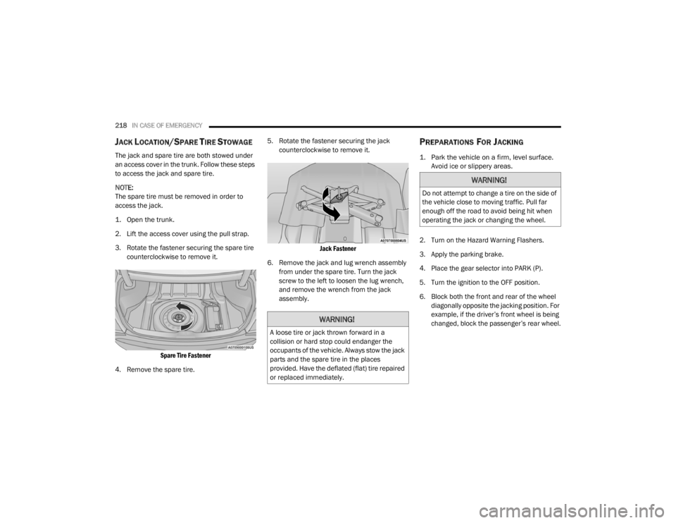
3. Rotate the fastener securing the spare tire
counterclockwise to remove it.
Spare Tire Fastener
4. Remove the spare tire. 5. Rotate the fastener securing the jack
counterclockwise to remove it.
Jack Fastener
6. Remove the jack and lug wrench assembly from under the spare tire. Turn the jack
screw to the left to loosen the lug wrench,
and remove the wrench from the jack
assembly.
PREPARATIONS FOR JACKING
1. Park the vehicle on a firm, level surface. Avoid ice or slippery areas.
2. Turn on the Hazard Warning Flashers.
3. Apply the parking brake.
4. Place the gear selector into PARK (P).
5. Turn the ignition to the OFF position.
6. Block both the front and rear of the wheel diagonally opposite the jacking position. For
example, if the driver’s front wheel is being
changed, block the passenger’s rear wheel.
WARNING!
A loose tire or jack thrown forward in a
collision or hard stop could endanger the
occupants of the vehicle. Always stow the jack
parts and the spare tire in the places
provided. Have the deflated (flat) tire repaired
or replaced immediately.
WARNING!
Do not attempt to change a tire on the side of
the vehicle close to moving traffic. Pull far
enough off the road to avoid being hit when
operating the jack or changing the wheel.
20_LX_OM_EN_USC_t.book Page 218
Page 222 of 328
220IN CASE OF EMERGENCY
3. Before raising the vehicle, use the lug
wrench to loosen, but not remove, the lug
nuts on the wheel with the flat tire. Turn the
lug nuts counterclockwise one turn while
the wheel is still on the ground.
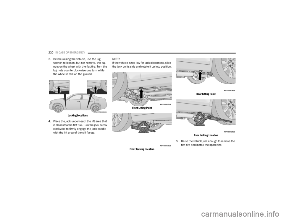
Jacking Locations
4. Place the jack underneath the lift area that is closest to the flat tire. Turn the jack screw
clockwise to firmly engage the jack saddle
with the lift area of the sill flange. NOTE:
If the vehicle is too low for jack placement, slide
the jack on its side and rotate it up into position.
Front Lifting Point
Front Jacking Location Rear Lifting Point
Rear Jacking Location
5. Raise the vehicle just enough to remove the flat tire and install the spare tire.
20_LX_OM_EN_USC_t.book Page 220
Page 223 of 328

IN CASE OF EMERGENCY221
6. Remove the lug nuts and tire.
7. Mount the spare tire.
Mounting Spare Tire
NOTE:
For vehicles so equipped, do not attempt to
install a center cap or wheel cover on the
compact spare.
Refer to “Compact Spare Tire” and to
“Limited-Use Spare” under “Tires” in
“Servicing And Maintenance” for additional
warnings, cautions, and information about
the spare tire, its use, and operation.
8. Install the lug nuts with the cone shaped end of the lug nut toward the wheel. Lightly
tighten the lug nuts.
9. Lower the vehicle to the ground by turning the jack handle counterclockwise. 10. Finish tightening the lug nuts. Push down on
the wrench while at the end of the handle
for increased leverage. Tighten the lug nuts
in a star pattern until each nut has been
tightened twice. For the correct lug nut
torque, refer to “Wheel And Tire Torque
Specifications” in “Technical Specifi -
cations”. If in doubt about the correct
tightness, have them checked with a torque
wrench by an authorized dealer or at a
service station.
11. Stow the jack, tools and flat tire. Make sure the base of the jack faces the front of the
vehicle before tightening down the fastener.
WARNING!
Raising the vehicle higher than necessary can
make the vehicle less stable. It could slip off
the jack and hurt someone near it. Raise the
vehicle only enough to remove the tire.
CAUTION!
Be sure to mount the spare tire with the valve
stem facing outward. The vehicle could be
damaged if the spare tire is mounted
incorrectly.
WARNING!
To avoid the risk of forcing the vehicle off the
jack, do not tighten the wheel nuts fully until
the vehicle has been lowered. Failure to
follow this warning may result in serious
injury.WARNING!
A loose tire or jack thrown forward in a
collision or hard stop could endanger the
occupants of the vehicle. Always stow the jack
parts and the spare tire in the places
provided. Have the deflated (flat) tire repaired
or replaced immediately.
6
20_LX_OM_EN_USC_t.book Page 221
Page 257 of 328

SERVICING AND MAINTENANCE255
R = Construction code
"R" means radial construction, or
"D" means diagonal or bias construction
15, 16, 18 = Rim diameter in inches (in)
Service Description:
95 = Load Index
A numerical code associated with the maximum load a tire can carry
H = Speed Symbol
A symbol indicating the range of speeds at which a tire can carry a load corresponding to its load index under certain operating conditions
The maximum speed corresponding to the speed symbol should only be achieved under specified operating conditions (i.e., tire pressure, vehicle
loading, road conditions, and posted speed limits)
Load Identification:
Absence of the following load identification symbols on the sidewall of the tire indicates a Standard Load (SL) tire:
XL = Extra load (or reinforced) tire, or
LL = Light load tire or
C, D, E, F, G = Load range associated with the maximum load a tire can carry at a specified pressure
Maximum Load – Maximum load indicates the maximum load this tire is designed to carry
Maximum Pressure – Maximum pressure indicates the maximum permissible cold tire inflation pressure for this tire
EXAMPLE:
7
20_LX_OM_EN_USC_t.book Page 255
Page 259 of 328
SERVICING AND MAINTENANCE257
Tire Terminology And Definitions
Tire Loading And Tire Pressure
NOTE:
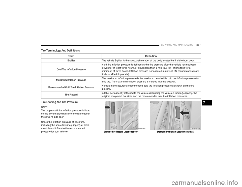
The proper cold tire inflation pressure is listed
on the driver’s side B-pillar or the rear edge of
the driver's side door.
Check the inflation pressure of each tire,
including the spare tire (if equipped), at least
monthly and inflate to the recommended
pressure for your vehicle.
Example Tire Placard Location (Door)Example Tire Placard Location (B-pillar)
Term Definition
B-pillarThe vehicle B-pillar is the structural member of the body located behind the front door.
Cold Tire Inflation Pressure Cold tire inflation pressure is defined as the tire pressure after the vehicle has not been
driven for at least three hours, or driven less than 1 mile (1.6 km) after sitting for a
minimum of three hours. Inflation pressure is measured in units of PSI (pounds per square
inch) or kPa (kilopascals).
Maximum Inflation Pressure The maximum inflation pressure is the maximum permissible cold tire inflation pressure for
this tire. The maximum inflation pressure is molded into the sidewall.
Recommended Cold Tire Inflation Pressure Vehicle manufacturer's recommended cold tire inflation pressure as shown on the tire
placard.
Tire Placard A label permanently attached to the vehicle describing the vehicle’s loading capacity, the
original equipment tire sizes and the recommended cold tire inflation pressures.
7
20_LX_OM_EN_USC_t.book Page 257
Page 260 of 328
258SERVICING AND MAINTENANCE
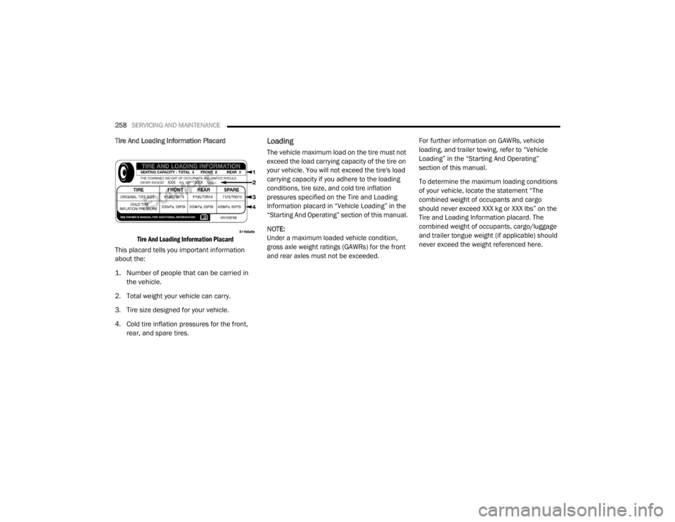
Tire And Loading Information Placard
Tire And Loading Information Placard
This placard tells you important information
about the:
1. Number of people that can be carried in the vehicle.
2. Total weight your vehicle can carry.
3. Tire size designed for your vehicle.
4. Cold tire inflation pressures for the front, rear, and spare tires.Loading
The vehicle maximum load on the tire must not
exceed the load carrying capacity of the tire on
your vehicle. You will not exceed the tire's load
carrying capacity if you adhere to the loading
conditions, tire size, and cold tire inflation
pressures specified on the Tire and Loading
Information placard in “Vehicle Loading” in the
“Starting And Operating” section of this manual.
NOTE:
Under a maximum loaded vehicle condition,
gross axle weight ratings (GAWRs) for the front
and rear axles must not be exceeded. For further information on GAWRs, vehicle
loading, and trailer towing, refer to “Vehicle
Loading” in the “Starting And Operating”
section of this manual.
To determine the maximum loading conditions
of your vehicle, locate the statement “The
combined weight of occupants and cargo
should never exceed XXX kg or XXX lbs” on the
Tire and Loading Information placard. The
combined weight of occupants, cargo/luggage
and trailer tongue weight (if applicable) should
never exceed the weight referenced here.
20_LX_OM_EN_USC_t.book Page 258