Page 249 of 278

83A012721BB
Emergency assistance
Read and follow the important information under
=> page 246.
Preparations
> Only secure the towing cable or tow bar at the
designated towing loops > page 247,
=> page 247.
> Make sure the towing cable is not twisted. Oth-
erwise it could disconnect from the towing loop
while towing.
> Switch the emergency flashers on in both
vehicles > page 46. However, do not do this if it
prohibited by law.
Towing vehicle (front)
> Only start to drive when the towing cable is
taut.
> Press the brake pedal very carefully.
> Avoid sudden braking or driving maneuvers.
Vehicle being towed (rear)
> Make sure the ignition is switched on so that
the steering wheel is not locked and so that you
can use the turn signals, the horn, and the
windshield wipers if needed > A\.
> Switching it off before the vehicle has stopped
may impair the function of the brake booster
and power steering. You would then need to
use more force to steer and brake the vehicle.
> Release the parking brake > page 93.
» Select the “N” selector lever position.
> Make sure the towing cable is always taut.
ZX WARNING
Never tow a vehicle using a tow bar or towing
cable if the vehicle does not have electrical
power.
Front towing loop
Fig. 163 Front bumper: installing the towing loop
The threaded opening for the towing loop is lo-
cated on the right side of the front bumper.
> Remove the towing loop from the vehicle tool
kit > page 240.
> Press the cap inward with brief, strong pressure
> fig. 163. The cap will loosen from the bump-
er.
> Tighten the towing loop in the threaded open-
ing until it stops and then tighten it with a
wheel wrench.
> After using, place the towing loop back in the
vehicle tool kit.
ZX WARNING
If the towing loop is not tightened until it
stops when installing, the threads may be
pulled out when towing the vehicle and result
in an accident.
@) Tips
Depending on the model, the shape of the
cover can vary.
Rear towing loop
Fig. 164 Rear bumper: installing the towing loop
247
Page 250 of 278
Emergency assistance
The threaded opening for the towing loop is lo-
cated on the right rear of the bumper.
> Remove the towing loop from the vehicle tool
kit > page 240.
> Press the cap inward with brief, strong pressure
> fig. 164. The cap will loosen from the bump-
er.
> Tighten the towing loop in the threaded open-
ing until it stops and then tighten it with a
wheel wrench.
> After using, place the towing loop back in the
vehicle tool kit.
If the towing loop is not tightened until it
stops when installing, the threads may be
pulled out when towing the vehicle and result
in an accident.
Depending on the model, the shape of the
cover can vary.
248
Page 251 of 278

83A012721BB
Fuses and bulbs
Fuses and bulbs
Fuses
Seale mie
Fig. 166 Left side of cockpit: storage compartment or
glove compartment (right-hand drive vehicles)
A fuse that has blown will have metal strips that
have burned through.
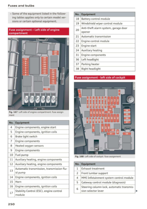
The fuses are located in the left side of the en-
gine compartment (@), behind the storage com-
partment in the left side of the cockpit (2) or the
glove compartment (8) (right-hand drive
vehicles).
> Switch the ignition and all electrical equipment
off.
> Check the table that follows to see which fuse
belongs to the equipment.
> Remove the screwdriver from the vehicle tool
kit > page 240.
> Remove the appropriate cover.
» Remove the clamp from the rear side of the
fuse cover ().
> Remove the fuse using the clip.
>» Replace the blown fuse only with a fuse that
has the same amp rating.
> Install the cover.
Fuse color identification
Black 1
Gray 2
Purple 3
Pink 4
Light brown 5
Brown AS:
Red 10
Light blue 15
Yellow 20
White or transparent |25
Light green 30
Teal 35
Orange 40
) Do not repair fuses and never replace a blown
fuse with one that has a higher amp rating.
This can cause damage to the electrical sys-
tem and increases the risk of fire.
@)
If a new fuse burns out again shortly after you
have installed it, have the electrical system
checked as soon as possible by an authorized
Audi dealer or authorized Audi Service Facili-
— The following table does not list fuse loca-
tions that are not used.
249
Page 252 of 278

Fuses and bulbs
— Some of the equipment listed in the follow-
ing tables applies only to certain model ver-
sions or certain optional equipment.
Fig. 167 Left side of engine compartment: fuse assign-
ment
No. | Equipment
Engine components, engine start
Engine components, ignition coils
Brake light switch
Engine components
Heated oxygen sensors
OlOAIN
I
DA/Mm|A
Engine components
10 | Fuel pump
11 | Auxiliary heating, engine components
No. Equipment
18 Battery control module
19 Windshield wiper control module
20
Anti-theft alarm system, garage door
opener
21 Automatic transmission
22 Engine control module
23 Engine start
24 Auxiliary heating
31 Engine components
36 Left headlight
37 Parking heater
38
Right headlight
Fig. 168 Left side of cockpit: fuse assignment
Stability Control (ESC), engine control
17
module
250
12 | Auxiliary heating, engine components No. | Equipment
13 Automatic transmission, transmission flu- 1 | Exhaust treatment
id pump 2 | Front lumbar support
14 | Engine components, ignition coils 4 |MMI Infotainment system control module
15 | Horn 5 | Gateway control module (diagnosis)
16 | Engine components, ignition coils 5 Steering column lock, automatic transmis-
sion selector lever
Page 253 of 278

83A012721BB
Fuses and bulbs
No. | Equipment No. | Equipment
7 Radio receiver, parking heater, climate Right rear window regulator motor, front
control system controls 39 | passenger side door control module, right
Headlight range control, interior monitor- rear door control module
ing, ambient lighting, light switch, roof 40 | Sockets
8 | module, emergency call system, parking 41 |Passenger's side safety belt tensioner
brake, diagnostic connector, light/raih'sen- 42 |Vehicle electrical system control module
sor
= - 43 |Sound-amplifier
9 |Steering column electronics
- - 44 | All-wheel drive control module (quattro)
Display, MMI Infotainment system control
10 anadtile 4S Driver's side seat adjustment
11 | Vehicle electrical system control module 47 | Rearwindow wiper
12 |MMI Infotainment system control module a6 || Exteriorsound
13 | Driver's side safety belt tensioner 50 | tuggage: compartment lid
14 | Heating and A/C system blower 52. || Suspension
15 | Steering column lock 53 | Rear;window defogger
16 |MMI Infotainment system control module 54 | Left trailer hitch light
17 |Instrument cluster 29 | Ualler hitch
18 | Rearview camera, peripheral cameras 56. | Right trailer hitch light
19 | Vehicle opening/start (NFC) 87 [Trailer'hitch'socket
20 | Exhaust treatment, instrument cluster
; Bulbs
21 | Steering column electronics
23 | Panoramic glass roof Replacing bulbs
24 | Vehicle electrical system control module
25
Driver side door control module, left rear
window regulator motor, left rear door
control module
26 Vehicle electrical system control module
27 Vehicle electrical system control module
29
Roof module, vehicle electrical system
control module
30 Auxiliary battery control module
31 Luggage compartment lid
32 Driver assistance systems
33
Passenger occupant detection system,
front seat ventilation, headliner interior
light
34
A/C system components, parking brake,
reverse lights
35
A/C system components, diagnostic con-
nector, instrument panel control, rearview
mirror
Having a bulb replaced by an authorized Audi
dealer or authorized Audi Service Facility in cases
of doubt is recommended. These facilities have
the correct tools and replacement parts as well
as the required technical knowledge.
LED lights*
Your vehicle is equipped with maintenance-free
headlights and tail lights. However, if a light bulb
needs to be replaced, please contact an author-
ized Audi dealer or authorized Audi Service Facili-
ty.
ZA\ WARNING
If you still would like to try replacing the
bulbs in your vehicle yourself, read the warn-
ings regarding working in the engine compart-
ment > A\ in General information on
page 201. >
251
Page 254 of 278
Fuses and bulbs
Make sure the covers are fitted correctly on
the headlight and tail light so that no water
will leak in from the outside and the light
function will not be impaired.
252
Page 255 of 278

83A012721BB
Data privacy
Data privacy
Image recording
Surrounding area monitoring
Applies to: vehicles with surrounding area monitoring
Some vehicle functions require the vehicle’s path
to be detected and evaluated. This is done by
cameras installed permanently on the vehicle
that detect objects in the vehicle's surroundings
(such as obstacles or guard rails). The live images
from the cameras are transmitted to the applica-
ble control module.
The camera images are transferred to the respon-
sible control module for processing and may be
stored, depending on vehicle equipment. The
control
module analyzes the current camera im-
age using image evaluation software. This image
evaluation software detects anonymized techni-
cal measurements, such as distances to objects.
The control module evaluates these technical
measurements and makes it possible for the as-
sist systems to control the vehicle, if necessary.
Data memories
Vehicle control modules
B4H-0657
|
Fig. 169 Driver's side footwell: connection port for the On
Board Diagnostic System (OBD)
Your vehicle is equipped with electronic control
modules for various vehicle systems such as the
airbags. These vehicle control modules store data
while driving normally that is required by an au-
thorized Audi dealer or authorized Audi Service
Facility for diagnosis and repair purposes. Only
certain types of data are recorded for a very short
period of time if a control module has detected a
system event. No noises, conversations, or im-
ages will be recorded in the vehicle.
The data may include information such as the ve-
hicle speed, the direction of travel, and informa-
tion about the brake system, or also the behavior
of the restraint system in the event of an acci-
dent. The stored data can be exported and down-
loaded with special devices, which must be con-
nected directly to the vehicle.
On Board Diagnostic System (OBD)
There is a diagnostic connector socket in the driv-
er's side footwell to read out the various control
modules and the event data recorder. Data re-
garding the function and condition of the elec-
tronic control modules is stored in the event
memory. Only have an authorized Audi dealer or
authorized Audi Service Facility read out and de-
lete the event memory.
Z\ WARNING
— Incorrect use of the connection port for the
On Board Diagnostic System can cause mal-
functions, which can then result in accidents
and serious injuries.
— Only allow an authorized Audi dealer or au-
thorized Audi Service Facility to read out the
engine data.
Crash data recorder
Event Data Recorder
This vehicle is equipped with an Event Data Re-
corder (EDR). The main purpose of an EDR is to
record, in certain crash or near crash-like situa-
tions,
such as an airbag deployment or hitting a
road obstacle, data that will assist in understand-
ing how a vehicle's system performed. The EDR is
designed to record data related to vehicle dynam-
ics and safety systems for a short period of time,
typically 30 seconds or less. The EDR in this vehi-
cle is designed to record such data as:
— How various systems in your vehicle were oper-
ating;
— Whether or not the driver and passenger safety
belts were buckled/fastened;
253
Page 256 of 278

Data privacy
— How far (if at all) the driver was depressing the
accelerator and/or brake pedal; and,
— How fast the vehicle was traveling.
These data can help provide a better understand-
ing of the circumstances in which crashes and in-
juries occur. NOTE: EDR data are recorded by your
vehicle only if a non-trivial crash situation occurs;
no data are recorded by the EDR under normal
driving conditions and no personal data (e.g.
name, gender, age, and crash location) are re-
corded. However, other parties, such as law en-
forcement, could combine the EDR data with the
type of personally identifying data routinely ac-
quired during a crash investigation.
To read data recorded by an EDR, special equip-
ment is required, and access to the vehicle or the
EDR is needed. In addition to the vehicle manu-
facturer, other parties, such as law enforcement,
that have the special equipment, can read the in-
formation if they have access to the vehicle or the
EDR.
Assist system monitor
This vehicle is equipped with an Assist System
Monitor (ASM). The ASM collects data that is not
stored by the EDR in the event of an accident. The
main task of the ASM is to make it possible to un-
derstand the role and the behavior of the assist
systems in these accident situations. In addition
to the data that the EDR stores, the ASM records
data related to the assist systems starting sever-
al seconds before the accident or near-accident.
The data collected by ASM depends on the equip-
ment and may include the following information:
status information of the assist systems (for ex-
ample, if they are switched on or off, system
events, etc.), control interventions (for example,
by ESC, ABS, Audi pre sense”, etc.), and assist
systems settings (such as speed settings).
Special devices and access to the vehicle or to the
ASM are necessary in order to read the data from
the ASM memory. In addition to the vehicle man-
ufacturer, third parties such as law enforcement
authorities can also read and analyze the stored
data if they have access to the vehicle or to the
ASM.
254
Data usage
Audi can read out the information stored in the
data memories or similar data, or give this infor-
mation to third parties, especially in the follow-
ing situations:
— If the vehicle owner or lessee agrees
— If there is an official request from the police
— Ifa court or authorities request it
If legally permitted, Audi can also use the data
for analysis of vehicle operation and safety per-
formance or provide this data to third parties for
research purposes.
Transmitted information
Privacy settings
Applies to: vehicles with Audi connect
> Applies to MMI: Select on the home screen:
SETTINGS > Privacy settings.
Data is transmitted from the vehicle when using
Audi connect services.
> To display additional information about the pri-
vacy settings and the associated symbols in the
status bar, press @ in the MMI.
Requirement: the ignition must be switched on.
Setting the maximum privacy settings
When the Activate privacy mode function is
switched on, the data connection is deactivated
or sending of data is restricted, but all safety-re-
lated, legal, or contractually required Audi con-
nect services remain activated. The majority of
the Audi connect services are deactivated.
When the function is switched off, the data con-
nection will be available in order to use Audi con-
nect services.
Adjusting individual privacy settings
In the MMI, you can adjust individually which da-
ta should be transmitted from the vehicle. If you
switch on a data category, the data will be trans-
mitted.