Page 97 of 120

Periodic maintenance an d a djustment
6-28
6
EAUM1653
Lu bricatin g the swin garm piv-
otsThe swingarm pivots must be lubricat-
ed by a Yamaha dealer at the intervals
specified in the periodic maintenance
and lubrication chart.
EAU23273
Checkin g the front forkThe condition and operation of the
front fork must be checked as follows
at the intervals specified in the periodic
maintenance and lubrication chart.
To check the con dition
Check the inner tubes for scratches,
damage and excessive oil leakage.
To check the operation 1. Place the vehicle on a level surfa- ce and hold it in an upright posi-
tion. WARNING! To avoi d injury,
securely support the vehicle so
there is no dan ger of it fallin g
over.
[EWA10752]
2. While applying the front brake, push down hard on the handle-
bars several times to check if the
front fork compresses and re-
bounds smoothly.
Recommen ded lu bricant:
Lithium-soap-based grease
Recommen ded lu bricant:
Lithium-soap-based grease
UB1JE1E0.book Page 28 Thursday, October 11, 2018 10:43 AM
Page 98 of 120

Periodic maintenance an d a djustment
6-29
6
NOTICE
ECA10591
If any d amage is foun d or the front
fork does not operate smoothly,
have a Yamaha d ealer check or re-
pair it.
EAU45512
Checkin g the steerin gWorn or loose steering bearings may
cause danger. Therefore, the operation
of the steering must be checked as fol-
lows at the intervals specified in the
periodic maintenance and lubrication
chart.
1. Place the vehicle on the center- stand. WARNING! To avoi d inju-
ry, securely support the vehicle
so there is no dan ger of it fallin g
over.
[EWA10752]
2. Hold the lower ends of the front fork legs and try to move them for-
ward and backward. If any free
play can be felt, have a Yamaha
dealer check or repair the steer-
ing.
EAU23292
Checkin g the wheel bearin gsThe front and rear wheel bearings must
be checked at the intervals specified in
the periodic maintenance and lubrica-
tion chart. If there is play in the wheel
hub or if the wheel does not turn
smoothly, have a Yamaha dealer
check the wheel bearings.
UB1JE1E0.book Page 29 Thursday, October 11, 2018 10:43 AM
Page 99 of 120

This model is equipped with a VRLA
(Valve Regulated Lead Acid) battery.
There")
Periodic maintenance an d a djustment
6-30
6
EAU50212
BatteryThe battery is located under the rider
seat. (See page 3-34.)
This model is equipped with a VRLA
(Valve Regulated Lead Acid) battery.
There is no need to check the electro-
lyte or to add distilled water. However,
the battery lead connections need to
be checked and, if necessary, tight-
ened.
WARNING
EWA10761
Electrolyte is poisonous an d
d an gerous since it contains sul-
furic aci d, which causes severe b
urns. Avoi d any contact with
skin, eyes or clothin g an d al-
ways shiel d your eyes when
workin g near b atteries. In case
of contact, ad minister the fol-
lowin g FIRST AID.
EXTERNAL: Flush with plenty of water.
INTERNAL: Drink lar ge quan-
tities of water or milk an d im-
me diately call a physician.
EYES: Flush with water for 15 minutes an d seek prompt
me dical attention.
Batteries pro duce explosive hy-
d ro gen gas. Therefore, keep
sparks, flames, ci garettes, etc.,
away from the b attery and pro-
vi de sufficient ventilation when
char gin g it in an enclose d
space.
KEEP THIS AND ALL BATTER-
IES OUT OF THE REACH OF
CHILDREN.
To char ge the b attery
Have a Yamaha dealer charge the bat-
tery as soon as possible if it seems to
h a ve d is c h ar g e d . K e e p i n m i nd th a t th e battery tends to discharge more quick-
ly if the vehicle is equipped with op-
tional electrical accessories.
NOTICE
ECA16522
To char
ge a VRLA (Valve Re gulate d
Lea d Aci d) battery, a special (con-
stant-volta ge) battery char ger is re-
quire d. Usin g a conventional b attery
char ger will d amage the battery.To store the battery
1. If the vehicle will not be used for more than one month, remove the
battery, fully charge it, and then
place it in a cool, dry place.
NOTICE: When removin g the
b attery, be sure to turn the main
switch off, then d isconnect the
ne gative lead before discon-
nectin g the positive lea d.
[ECA16304]
2. If the battery will be stored for
more than two months, check it at
least once a month and fully char-
ge it if necessary.
3. Fully charge the battery before installation. NOTICE: When in-
stallin g the b attery, be sure to
turn the main switch off, then
1. Battery
2. Positive battery lead (red)
3. Negative battery lead (black)
1
3
2
UB1JE1E0.book Page 30 Thursday, October 11, 2018 10:43 AM
Page 100 of 120
![YAMAHA TRACER 900 GT 2019 Owners Manual Periodic maintenance an d a djustment
6-31
6 connect the positive lea
d b efore
connectin g the ne gative lead .
[ECA16842]
4. After installation, make sure that
the battery leads are properly con-
ne](/manual-img/51/51871/w960_51871-99.png "YAMAHA TRACER 900 GT 2019 Owners Manual Periodic maintenance an d a djustment
6-31
6 connect the positive lea
d b efore
connectin g the ne gative lead .
[ECA16842]
4. After installation, make sure that
the battery leads are properly con-
ne")
Periodic maintenance an d a djustment
6-31
6 connect the positive lea
d b efore
connectin g the ne gative lead .
[ECA16842]
4. After installation, make sure that
the battery leads are properly con-
nected to the battery terminals.NOTICE
ECA16531
Always keep the b attery charged .
Storin g a d ischar ged battery can
cause permanent battery dama ge.
EAU63134
Replacin g the fusesThe fuse boxes and individual fuses
are located under the rider seat (see
page 3-34) and behind panel A (see
page 6-9).
To access fuse box 1, the main fuse,
and the fuel injection system fuse, re-
move the rider seat. (See page 3-34.)
TIPTo access the fuel injection system
fuse, remove the starter relay cover by
pulling it upward.
1. Fuse box 1
2. Main fuse
3. Fuel injection system fuse
4. Fuel injection system spare fuse1 3
4
2
1. Radiator fan motor fuse
2. Backup fuse (for clock and immobilizer sys- tem)
3. Electronic throttle valve fuse
4. ABS solenoid fuse
5. ABS motor fuse
6. Spare fuse
1
2
345
6
UB1JE1E0.book Page 31 Thursday, October 11, 2018 10:43 AM
Page 101 of 120

If a fuse is blown, replace it as follows.1. Turn the key to “OFF” and turn off th")
Periodic maintenance an d a djustment
6-32
6
To access fuse box 2 and fuse box 3,
remove panel A. (See page 6-9.)
If a fuse is blown, replace it as follows.1. Turn the key to “OFF” and turn off the electrical circuit in question.
2. Remove the blown fuse, and then install a new fuse of the specified
amperage. WARNING! Do not
use a fuse of a hi gher ampera ge
ratin g than recommen ded to avoi
d causin g extensive dam-
a g e to the electrical system an d
possi bly a fire.
[EWA15132]
1. Starter relay cover
2. Fuel injection system fuse
3. Fuel injection system spare fuse
1. Fuse box 2
2. Fuse box 3
3
2
1
1
2
1. Parking lighting fuse
2. Headlight fuse
3. Plug +12V fuse (DC connector, option)
4. Plug +12V fuse (DC jack)
5. Cruise control fuse
6. Brake light fuse
7. Signaling system fuse
8. Fog lamp fuse (option)
9. ABS control unit fuse
10.Seat heater fuse (option)
11.Ignition fuse
12.Spare fuse
123412
111210987
6
5
Specified fuses:
Main fuse: 50.0 A
Fuel injection system fuse:
20.0 A
Specified fuses (fuse box 1):
Radiator fan motor fuse: 15.0 A
ABS motor fuse:
30.0 A
ABS solenoid fuse: 15.0 A
Backup fuse: 7.5 A
Electronic throttle valve fuse:
7.5 A
UB1JE1E0.book Page 32 Thursday, October 11, 2018 10:43 AM
Page 102 of 120

Periodic maintenance an d a djustment
6-33
6
3. Turn the key to “ON” and turn onthe electrical circuit in question to
check if the device operates.
4. If the fuse immediately blows again, have a Yamaha dealer
check the electrical system.
EAUN2261
Vehicle lig htsThis model is equipped with LED lights
for headlights, auxiliary lights and
brake/tail light. If a light does not come
on, check the fuse and then have a
Yamaha dealer check the vehicle.NOTICE
ECA16581
Do not affix any type of tinte d film or
stickers to the hea dlig ht lens.
EAU24205
Replacin g a turn si gnal li ght
b ul b1. Remove the turn signal light lens
by removing the screw.
2. Remove the burnt-out bulb by pushing it in and turning it coun-
terclockwise.
Specifie d fuses (fuse box 2):
Fog lamp fuse:
2.0 A
Brake light fuse:
1.0 A
Signaling system fuse: 7.5 A
Ignition fuse: 15.0 A
ABS control unit fuse:
7.5 A
Seat heater fuse: 7.5 A
Specifie d fuses (fuse box 3):
Headlight fuse:
7.5 A
Parking lighting fuse: 7.5 A
Cruise control fuse: 1.0 A
Plug +12V fuse:
2.0 A
Plug +12V fuse: 2.0 A
1. Headlight
2. Auxiliary light
21
21
1. Turn signal light lens
2. Screw
1
2
UB1JE1E0.book Page 33 Thursday, October 11, 2018 10:43 AM
Page 103 of 120
Periodic maintenance an d a djustment
6-34
6
3. Insert a new bulb into the socket,
push it in, and then turn it clock-
wise until it stops.
4. Install the lens by installing the screw. NOTICE: Do not over-
ti g hten the screw, otherwise the
lens may break.
[ECA11192] EAU58010
Replacin
g the license plate
lig ht bul b1. Remove the license plate light unit
by removing the nuts and collars,
and then remove the license plate
light bulb socket (together with the
bulb) by pulling it out.
2. Remove the burnt-out bulb by pulling it out. 3. Insert a new bulb into the socket.
4. Install the socket (together with
the bulb) by pushing it in, and then
install the license plate light unit by
installing the collars and nuts.
1. Turn signal light bulb
1
1. License plate light unit
2. Collar
3. Nut
4. License plate light bulb socket
1
22
4
3
3
1. License plate light bulb
1
UB1JE1E0.book Page 34 Thursday, October 11, 2018 10:43 AM
Page 104 of 120

Periodic maintenance an d a djustment
6-35
6
EAU25872
Trou bleshootin gAlthough Yamaha motorcycles receive
a thorough inspection before shipment
from the factory, trouble may occur
during operation. Any problem in the
fuel, compression, or ignition systems,
for example, can cause poor starting
and loss of power.
The following troubleshooting charts
represent quick and easy procedures
for checking these vital systems your-
self. However, should your motorcycle
require any repair, take it to a Yamaha
dealer, whose skilled technicians have
the necessary tools, experience, and
know-how to service the motorcycle
properly.
Use only genuine Yamaha replace-
ment parts. Imitation parts may look
like Yamaha parts, but they are often
inferior, have a shorter service life and
can lead to expensive repair bills.
WARNING
EWA15142
When checkin g the fuel system, do
not smoke, an d make sure there are
no open flames or sparks in the ar-
ea, inclu din g pilot lig hts from water heaters or furnaces. Gasoline or
g
asoline vapors can i gnite or ex-
plod e, causin g severe injury or prop-
erty dama ge.UB1JE1E0.book Page 35 Thursday, October 11, 2018 10:43 AM
 1
1 2
2 3
3 4
4 5
5 6
6 7
7 8
8 9
9 10
10 11
11 12
12 13
13 14
14 15
15 16
16 17
17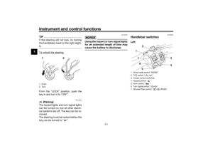 18
18 19
19 20
20 21
21 22
22 23
23 24
24 25
25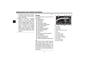 26
26 27
27 28
28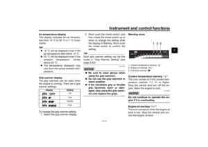 29
29 30
30 31
31 32
32 33
33 34
34 35
35 36
36 37
37 38
38 39
39 40
40 41
41 42
42 43
43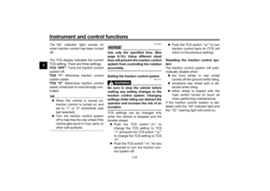 44
44 45
45 46
46 47
47 48
48 49
49 50
50 51
51 52
52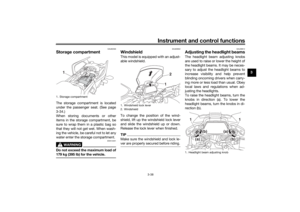 53
53 54
54 55
55 56
56 57
57 58
58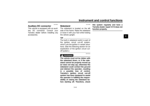 59
59 60
60 61
61 62
62 63
63 64
64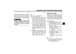 65
65 66
66 67
67 68
68 69
69 70
70 71
71 72
72 73
73 74
74 75
75 76
76 77
77 78
78 79
79 80
80 81
81 82
82 83
83 84
84 85
85 86
86 87
87 88
88 89
89 90
90 91
91 92
92 93
93 94
94 95
95 96
96 97
97 98
98 99
99 100
100 101
101 102
102 103
103 104
104 105
105 106
106 107
107 108
108 109
109 110
110 111
111 112
112 113
113 114
114 115
115 116
116 117
117 118
118 119
119