2019 Ram 1500 clock
[x] Cancel search: clockPage 70 of 698

“Slide-On-Rod” Features Of Sun Visor — If
Equipped
The sun visor “Slide-On-Rod” feature allows for additional
flexibility in positioning the visor to block out the sun.
To use the “Slide-On-Rod” feature, rotate the sun visor
downward and unclip it. Pull the sun visor along the
“Slide-On-Rod” until the sun visor is in the desired posi-
tion.
EXTERIOR LIGHTS
Headlight Switch
The headlight switch is located on the left side of the
instrument panel. This switch controls the operation of the
headlights, parking lights, automatic headlights — if
equipped, instrument panel light dimming, cargo light — if
equipped, and fog lights — if equipped.
Rotate the headlight switch clockwise to the first detent for
parking light and instrument panel light operation. Rotate
the headlight switch to the second detent for headlight,
parking light, and instrument panel light operation.
“Slide-On-Rod” Extender
Headlight Switch
68 GETTING TO KNOW YOUR VEHICLE
Page 73 of 698
The Automatic High Beams can also be deactivated
through the Uconnect system. Refer to “Uconnect Settings”
in “Multimedia” for further information.
Flash-To-Pass
You can signal another vehicle with your headlights by
lightly pulling the multifunction lever toward you. This
will cause the high beam headlights to turn on, and remain
on, until the lever is released.
Automatic Headlights — If Equipped
This system automatically turns your headlights on or off
based on ambient light levels. To turn the system on, turn
the headlight switch to the extreme clockwise position
aligning the indicator with the AUTO on the headlight
switch. When the system is on, the Headlight Time Delay
feature is also on. This means your headlights will stay on
for up to 90 seconds after you turn the ignition switch OFF.
To turn the Automatic System off, turn the headlight switch
counterclockwise to the O (off) position.
NOTE:The engine must be running before the headlights
will come on in the Automatic mode.
Parking Lights And Panel Lights
To turn on the parking lights and instrument panel lights, from the O (off) position, rotate the headlight switch
clockwise to the first detent. To turn off the parking
lights, rotate the headlight switch back to the O (off)
position.
Headlights On With Wipers (Available With
Automatic Headlights Only)
When this feature is active, the headlights will turn on
approximately 10 seconds after the wipers are turned on if
the headlight switch is placed in the AUTO position. In
addition, the headlights will turn off when the wipers are
turned off, if they were turned on by this feature.
NOTE: This feature can be programmed through the
Uconnect system. Refer to “Uconnect Settings” in “Multi-
media” for further information.
3
GETTING TO KNOW YOUR VEHICLE 71
Page 84 of 698
IconDescription
Temperature Control
Use this control knob to regulate the temperature of the air inside the passenger compartment. Ro-
tating the knob counterclockwise, from top center into the blue area of the scale, indicates cooler
temperatures. Rotating the knob clockwise, into the red area, indicates warmer temperatures.
Blower Control
There are seven blower speeds. Use this control knob to regulate the amount of air forced
through the system in any mode you select. The blower speed increases as you move the con-
trol clockwise from the off position.
Modes Control
Rotate the Mode Control Knob to change the airflow distribution mode. The airflow distribution
mode can be adjusted so air comes from the instrument panel outlets, floor outlets, defrost out-
lets and demist outlets. The Mode settings are as follows:
Panel Mode
Panel Mode
Air comes from the outlets in the instrument panel. Each of these outlets can be individually
adjusted to direct the flow of air. The air vanes of the center outlets and outboard outlets can be
moved up and down or side to side to regulate airflow direction. There is a shut off wheel lo-
cated below the air vanes to shut off or adjust the amount of airflow from these outlets.
Bi-Level Mode
Bi-Level Mode
Air comes from the instrument panel outlets and floor outlets. A slight amount of air is directed
through the defrost and side window demister outlets.
NOTE: Bi-Level mode is designed under comfort conditions to provide cooler air out of the
panel outlets and warmer air from the floor outlets.
82 GETTING TO KNOW YOUR VEHICLE
Page 92 of 698
IconDescription
Blower Control Knob
Blower ControlButtons
Blower Control
Blower Control is used to regulate the amount of air forced through the climate system. There
are seven blower speeds available. The speeds can be selected using either the blower control
knob on the faceplate, or the buttons on the touchscreen.
Control Knob — If Equipped: The blower speed increases as you turn the blower control knob
clockwise and decreases as you turn the blower control knob counterclockwise.
Faceplate — If Equipped: Use the arrow buttons on the faceplate to decrease or increase the
blower speed. Pressing the down arrow past the lowest setting turns the blower off.
Touchscreen: Use the blower icons to reduce or increase the blower setting. Blower can also be
selected by pressing the blower bar area between the icons.
Mode Control Knob
Mode ButtonMODE Modes Control
Control Knob:
Push the Mode Control Knob to change the airflow distribution mode. The air-
flow distribution mode can be adjusted so air comes from the instrument panel outlets, floor
outlets, defrost outlets and demist outlets.
Touchscreen: Press the “MODE” button to change the airflow distribution mode. The airflow
distribution mode can be adjusted so air comes from the instrument panel outlets, floor outlets,
defrost outlets and demist outlets.
The Mode settings are as follows:
90 GETTING TO KNOW YOUR VEHICLE
Page 140 of 698

Locking And Unlocking RamBox
Push and release the lock or unlock button on the key fob
to lock and unlock all doors, the tailgate and the RamBox
(if equipped). Refer to “Keys” in “Getting To Know Your
Vehicle” for further details. The RamBox storage bins can
also be locked using the emergency key. To lock and unlock
the storage bin, insert the emergency key into the keyhole
and turn clockwise to lock or counterclockwise to unlock.
Always return the key to the upright (vertical) position
before removing it from the keyhole.
CAUTION!
•Ensure cargo bin lids are closed and latched before
moving or driving vehicle.
• Loads applied to the top of the bin lid should be
minimized to prevent damage to the lid and latching/
hinging mechanisms.
• Damage to the RamBox bin may occur due to heavy/
sharp objects placed in bin that shift due to vehicle
motion. In order to minimize potential for damage,
secure all cargo to prevent movement and protect
inside surfaces of bin from heavy/sharp objects with
appropriate padding.
RamBox Safety Warning
Carefully follow these warnings to help prevent personal
injury or damage to your vehicle:
WARNING!
• Always close the storage bin covers when your
vehicle is unattended.
• Do not allow children to have access to the storage
bins. Once in the storage bin, young children may
not be able to escape. If trapped in the storage bin,
children can die from suffocation or heat stroke.
• In an accident, serious injury could result if the
storage bin covers are not properly latched.
• Do not drive the vehicle with the storage bin covers
open.
• Keep the storage bin covers closed and latched while
the vehicle is in motion.
• Do not use a storage bin latch as a tie down.
138 GETTING TO KNOW YOUR VEHICLE
Page 148 of 698
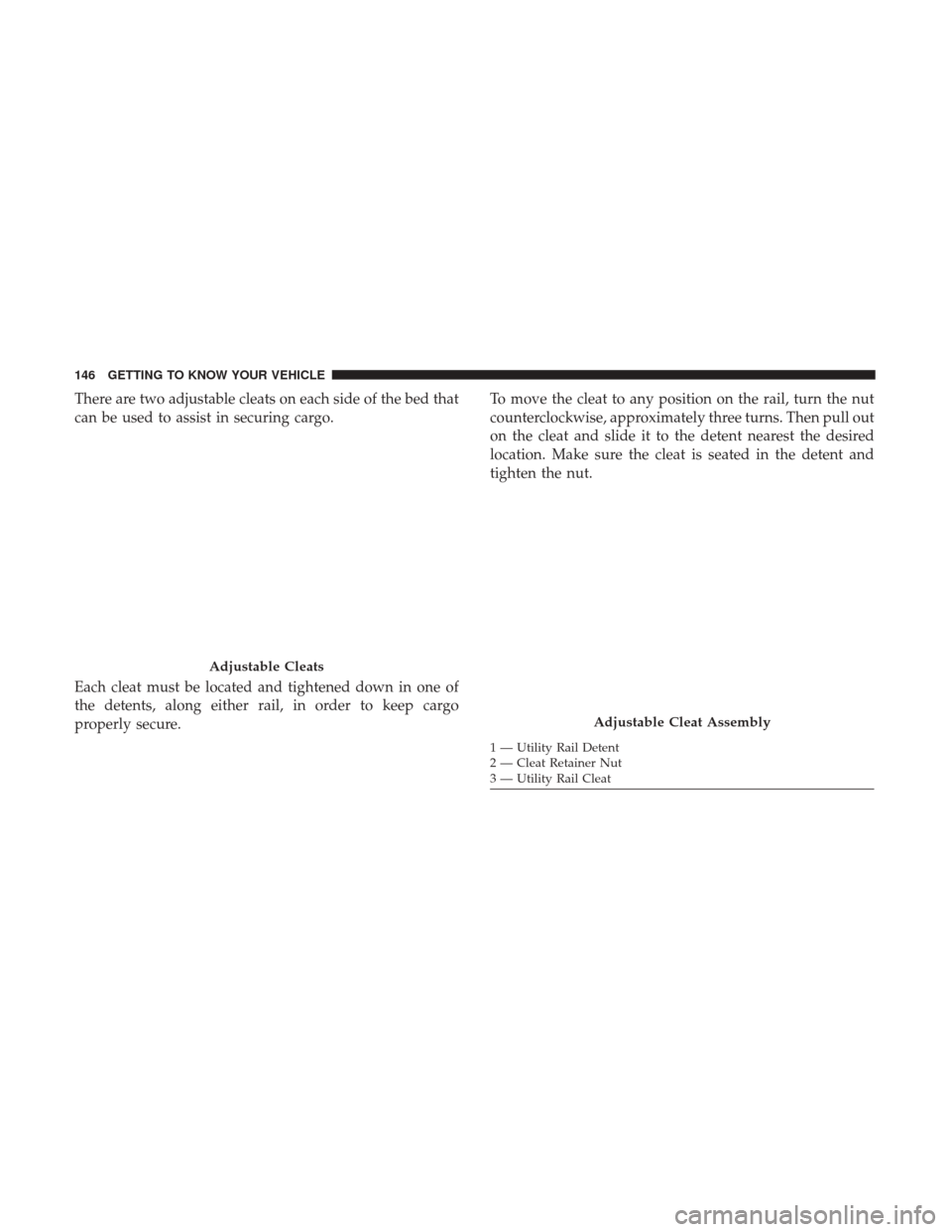
There are two adjustable cleats on each side of the bed that
can be used to assist in securing cargo.
Each cleat must be located and tightened down in one of
the detents, along either rail, in order to keep cargo
properly secure.To move the cleat to any position on the rail, turn the nut
counterclockwise, approximately three turns. Then pull out
on the cleat and slide it to the detent nearest the desired
location. Make sure the cleat is seated in the detent and
tighten the nut.
Adjustable Cleats
Adjustable Cleat Assembly
1 — Utility Rail Detent
2 — Cleat Retainer Nut
3 — Utility Rail Cleat
146 GETTING TO KNOW YOUR VEHICLE
Page 406 of 698

REFUELING THE VEHICLE
The fuel filler is located behind the fuel filler door, on the
left side of the vehicle.
There is no fuel filler cap. Two flapper doors inside the pipe
seal the system.
WARNING!
•Never have any smoking materials lit in or near the
vehicle when the fuel door is open or the tank is
being filled.
• Never add fuel when the engine is running. This is
in violation of most state and federal fire regulations
and may cause the MIL to turn on.
• A fire may result if gasoline is pumped into a
portable container that is inside of a vehicle. You
could be burned. Always place gas containers on the
ground while filling.
CAUTION!
To avoid fuel spillage and overfilling, do not “top off”
the fuel tank after filling.
1. Put the vehicle in park and switch the ignition off.
2. Push the center-rear edge of the fuel filler door (3 o’clock position) and release to open.
Fuel Filler Door
404 STARTING AND OPERATING
Page 407 of 698
3. Insert the fuel nozzle fully into the filler pipe, the nozzleopens and holds both flapper doors while refueling.
4. When the fuel nozzle “clicks” or shuts off, the fuel tank is full.
5. Keep the nozzle in the filler for five seconds after nozzle clicks to allow fuel to drain from the nozzle.
6. Remove the fuel filler nozzle.
7. To close the fuel filler door, push the center-rear edge (3 o’clock position) of the fuel filler door and then release.
The fuel filler door will latch closed. NOTE:
In certain cold conditions, ice may prevent the fuel
filler door from opening. If this occurs, lightly push on the
fuel filler door around the perimeter to break the ice build
up.
WARNING!
Static electricity can cause an ignition of flammable
liquid, vapor or gas in any vehicle or trailer. To reduce
risk of serious injury or death when filling containers:
• Always place container on the ground before filling.
• Keep the pump nozzle in contact with the container
when you are filling it.
• Use only approved containers for flammable liquid.
• Do not leave container unattended while filling.
• A static electric charge could cause a spark and fire
hazard.
Emergency Gas Can Refueling
Most gas cans will not open the flapper doors.
A funnel is provided to open the flapper doors to allow
emergency refueling with a gas can.
1. Retrieve funnel from the jack and jack tool kit.
Fuel Filler
6
STARTING AND OPERATING 405