Page 84 of 698

IconDescription
Temperature Control
Use this control knob to regulate the temperature of the air inside the passenger compartment. Ro-
tating the knob counterclockwise, from top center into the blue area of the scale, indicates cooler
temperatures. Rotating the knob clockwise, into the red area, indicates warmer temperatures.
Blower Control
There are seven blower speeds. Use this control knob to regulate the amount of air forced
through the system in any mode you select. The blower speed increases as you move the con-
trol clockwise from the off position.
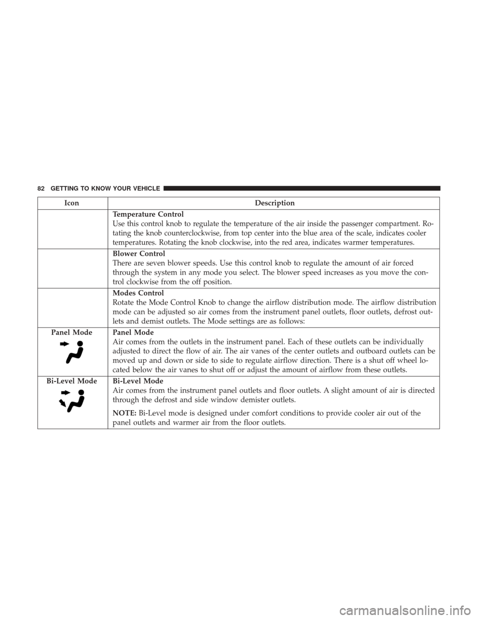
Modes Control
Rotate the Mode Control Knob to change the airflow distribution mode. The airflow distribution
mode can be adjusted so air comes from the instrument panel outlets, floor outlets, defrost out-
lets and demist outlets. The Mode settings are as follows:
Panel Mode
Panel Mode
Air comes from the outlets in the instrument panel. Each of these outlets can be individually
adjusted to direct the flow of air. The air vanes of the center outlets and outboard outlets can be
moved up and down or side to side to regulate airflow direction. There is a shut off wheel lo-
cated below the air vanes to shut off or adjust the amount of airflow from these outlets.
Bi-Level Mode
Bi-Level Mode
Air comes from the instrument panel outlets and floor outlets. A slight amount of air is directed
through the defrost and side window demister outlets.
NOTE: Bi-Level mode is designed under comfort conditions to provide cooler air out of the
panel outlets and warmer air from the floor outlets.
82 GETTING TO KNOW YOUR VEHICLE
Page 93 of 698

IconDescription
Panel Mode
Panel Mode
Air comes from the outlets in the instrument panel. Each of these outlets can be individually
adjusted to direct the flow of air. The air vanes of the center outlets and outboard outlets can be
moved up and down or side to side to regulate airflow direction. There is a shut off wheel lo-
cated below the air vanes to shut off or adjust the amount of airflow from these outlets.
Bi-Level Mode
Bi-Level Mode
Air comes from the instrument panel outlets and floor outlets. A slight amount of air is directed
through the defrost and side window demister outlets.
NOTE: Bi-Level mode is designed under comfort conditions to provide cooler air out of the
panel outlets and warmer air from the floor outlets.
Floor Mode
Floor Mode
Air comes from the floor outlets. A slight amount of air is directed through the defrost and side
window demister outlets.
Mix Mode
Mix Mode
Air is directed through the floor, defrost, and side window demister outlets. This setting works
best in cold or snowy conditions that require extra heat to the windshield. This setting is good
for maintaining comfort while reducing moisture on the windshield.
Rear Climate Rear Climate Control Button Press and release this button to access the rear climate controls. The indicator will illuminate
when the rear climate controls are on.
3
GETTING TO KNOW YOUR VEHICLE 91
Page 108 of 698
Sunroof Maintenance
Use only a non-abrasive cleaner and a soft cloth to clean the
glass panel.
Ignition Off Operation
The power sunroof switch will remain active for up to
approximately 10 minutes after the ignition switch is
turned to the OFF/LOCK position. Opening either front
door will cancel this feature.
NOTE:Ignition Off time is programmable through the
Uconnect System. Refer to “Uconnect Settings” in “Multi-
media” for further information.
HOOD
To Open The Hood
To open the hood, two latches must be released.
1. Pull the hood release lever located below the steering wheel at the base of the instrument panel.
Hood Release Location
106 GETTING TO KNOW YOUR VEHICLE
Page 133 of 698
If equipped, a 115 Volt (400 Watts Maximum) inverter may
be located inside the ram box of your vehicle. The inverter
can be turned on by the Instrument Panel Power Inverter
switch located to the left of the steering wheel. This
inverter can power cellular phones, electronics and other
low power devices requiring power up to 400 Watts.
Certain high-end video game consoles exceed this power
limit, as will most power tools.If equipped, there may be a 115 Volt (400 Watts Maximum)
inverter located to the right of the center stack, just below
the climate controls. This inverter can power cellular
phones, electronics and other low power devices requiring
power up to 400 Watts. Certain high-end video game
consoles exceed this power limit, as will most power tools.
Ram Box Power Inverter
Instrument Panel Power Inverter Switch
3
GETTING TO KNOW YOUR VEHICLE 131
Page 137 of 698

You can carry wide building materials (sheets of plywood,
etc.) by building a raised load floor. Place lumber across the
box in the indentations provided above the wheel housings
and in the bulkhead dividers to form the floor.
WARNING!
•The pickup box is intended for load carrying pur-
poses only, not for passengers, who should sit in
seats and use seat belts.
• Care should always be exercised when operating a
vehicle with unrestrained cargo. Vehicle speeds may
need to be reduced. Severe turns or rough roads may
cause shifting or bouncing of the cargo that may
result in vehicle damage. If wide building materials
are to be frequently carried, the installation of a
support is recommended. This will restrain the cargo
and transfer the load to the pickup box floor.
• If you wish to carry more than 600 lbs (272 kg) of
material suspended above the wheelhouse, supports
must be installed to transfer the weight of the load to
the pickup box floor or vehicle damage may result.
The use of proper supports will permit loading up to
the rated payload.
(Continued)
WARNING! (Continued)
•Unrestrained cargo may be thrown forward in an
accident causing serious or fatal injury.
There are stampings in the sheet metal on the inner side
bulkheads of the box in front of and behind both wheel
housings. Place wooden boards across the box from side to
side to create separate load compartments in the pickup
box.
There are four tie-down cleats bolted to the lower sides of
the pickup box that can sustain loads up to 1000 lbs
(450 kg) total.
RAMBOX — IF EQUIPPED
The RamBox system is an integrated pickup box storage
and cargo management system consisting of three features:
• Integrated box side storage bins
• Cargo extender/divider
• Bed rail tie-down system
NOTE: Bed rail tie-down system is also available for
vehicles not equipped with a RamBox.
3
GETTING TO KNOW YOUR VEHICLE 135
Page 169 of 698

INSTRUMENT CLUSTER DISPLAY
Your vehicle will be equipped with an instrument cluster
display, which offers useful information to the driver. With
the ignition in the STOP/OFF mode, opening/closing of a
door will activate the display for viewing, and display the
total miles, or kilometers, in the odometer. Your instrument
cluster display is designed to display important informa-
tion about your vehicle’s systems and features. Using a
driver interactive display located on the instrument panel,
your instrument cluster display can show you how sys-
tems are working and give you warnings when they are
not. The steering wheel mounted controls allow you to
scroll through the main menus and submenus. You can
access the specific information you want and make selec-
tions and adjustments.
Instrument Cluster Display Controls
The instrument cluster display features a driver-interactive
display that is located in the instrument cluster.
Base Instrument Cluster Display
1 – Instrument Cluster Display Controls
2 – Instrument Cluster Display Screen
4
GETTING TO KNOW YOUR INSTRUMENT PANEL 167
Page 170 of 698
The instrument cluster display menu items may consist of
the following:
•Speedometer
• Vehicle Info
• Driver Assist
• Fuel Economy Info
• Trip •
Stop/Start
• Trailer Tow
• Audio
• Stored Messages
• Screen Setup
• Vehicle Settings (Not Equipped with a Uconnect touch-
screen radio)
The system allows the driver to select information by
pushing the following instrument cluster display control
buttons located on the left side of the steering wheel:
Premium Instrument Cluster Display
1 – Instrument Cluster Display Controls
2 – Instrument Cluster Display Screen
Instrument Cluster Display Control Buttons
168 GETTING TO KNOW YOUR INSTRUMENT PANEL
Page 173 of 698

•Gauge Summary — If Equipped
• Engine Hours
Driver Assist — If Equipped
The Driver Assist menu displays the status of the ACC and
LaneSense systems.
Push and release the upordown arrow button until the
Driver Assist menu is displayed in the instrument cluster
display.
Adaptive Cruise Control (ACC) Feature
The instrument cluster display displays the current ACC
system settings. The information displayed depends on
ACC system status.
Push the Adaptive Cruise Control (ACC) on/off button
(located on the steering wheel) until one of the following
displays in the instrument cluster display:
Adaptive Cruise Control Off
When ACC is deactivated, the display will read “Adaptive
Cruise Control Off.” Adaptive Cruise Control Ready
When ACC is activated but the vehicle speed setting has
not been selected, the display will read “Adaptive Cruise
Control Ready.”
Push the SET + or the SET- button (located on the steering
wheel) and the following will display in the instrument
cluster display:
ACC SET
When ACC is set, the set speed will display in the
instrument cluster.
The ACC screen may display once again if any ACC
activity occurs, which may include any of the following:
•
Distance Setting Change
• System Cancel
• Driver Override
• System Off
• ACC Proximity Warning
• ACC Unavailable Warning
For further information, refer to “Adaptive Cruise Control
(ACC) — If Equipped” in “Starting And Operating.”
4
GETTING TO KNOW YOUR INSTRUMENT PANEL 171