2019 Peugeot Partner wheel
[x] Cancel search: wheelPage 193 of 312

191
F Check that the compressor switch is at the "O " position.
F
U
ncoil fully the electric cable, stowed under
the compressor.
F
C
onnect the compressor's electric plug to
the vehicle's 12
V socket.
F
S
witch on the ignition. Only the 12
V socket located at the front
of the vehicle can be used to power the
compressor. If a pressure of 2 bars is not reached after
7
m
inutes, this indicates that the tyre is not
repairable; contact a PEUGEOT dealer or
a qualified workshop for assistance.
F
O
nce the correct pressure is reached, put
the switch to the " O" position.
F
R
emove the kit then stow it.
Do not drive more than 125 miles (200 km)
with the repaired tyre; see a PEUGEOT
dealer or a qualified workshop to change
the tyre.
Should the pressure of one or more tyres
be adjusted, it is necessary to reinitialise
the under-inflation detection system.
For more information on Tyre under-
inflation detection , refer to the
corresponding section.
F
S
crew the pipe onto the valve and tighten
f i r m l y. F
S
tart the compressor by placing the switch
at position " I" and adjust the pressure to the
value shown on the vehicle's tyre pressure
label. To deflate: press the black button
located on the compressor pipe, near the
valve connection. The tyre inflation pressures are given on
this label.
Spare wheel
Scan the QR code on page 3 to view
explanatory videos.
Procedure for changing a damaged wheel with
the spare wheel using the tools provided with
the vehicle.
Checking/adjusting tyre
pressures
You can also use the compressor,
without injecting sealant, to check and, if
necessary, adjust the tyre pressures.
F
R
emove the valve cap from the tyre and
place it in a clean area.
F
U
ncoil the pipe stowed under the
compressor.
8
In the event of a breakdown
Page 194 of 312

192
Access to the spare wheel
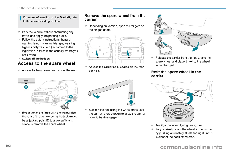
F Access to the spare wheel is from the rear.
F
I
f your vehicle is fitted with a towbar, raise
the rear of the vehicle using the jack (must
be at jacking point B ) to allow sufficient
space to remove the spare wheel.
Remove the spare wheel from the
carrier
F Depending on version, open the tailgate or the hinged doors.
F
A
ccess the carrier bolt, located on the rear
door sill.
F
S
lacken the bolt using the wheelbrace until
the carrier is low enough to allow the carrier
hook to be disengaged. F
R
elease the carrier from the hook, take the
spare wheel and place it next to the wheel
to be changed.
Refit the spare wheel in the
carrier
F Position the wheel facing the carrier.
F P rogressively return the wheel to the carrier
by pushing alternately at left and right until it
is clear of the hook fixing area.
For more information on the Tool kit
, refer
to the corresponding section.
F
P
ark the vehicle without obstructing any
traffic and apply the parking brake.
F
F
ollow the safety instructions (hazard
warning lamps, warning triangle, wearing
high visibility vest, etc.) according to the
legislation in force in the country where you
are driving.
F
S
witch off the ignition.
In the event of a breakdown
Page 195 of 312

193
Removing a wheel
Parking the vehicle
Immobilise the vehicle where it does not
block traffic: the ground must be level,
stable and non-slippery.
With a manual gearbox, engage first gear
then switch off the ignition to block the
wheels.
With an automatic gearbox, place the gear
selector in position P then switch off the
ignition to block the wheels.
Apply the parking brake and check that
the warning lamp is on in the instrument
panel.
The occupants must get out of the vehicle
and wait where they are safe.
Never go underneath a vehicle raised
using a jack; use an axle stand.
With an automatic electronic parking
brake, place a chock against the wheel
diagonally opposite to the one being
replaced.Wheel with wheel trim
When removing the wheel
, first remove
the wheel trim by pulling at the valve
aperture using the wheelbrace. Do not use:
-
t
he jack for any other purpose than
lifting the vehicle,
-
a j
ack other than the one supplied by
the manufacturer.
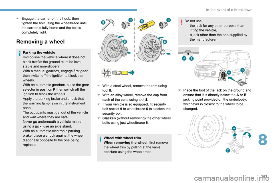
F
P
lace the foot of the jack on the ground and
ensure that it is directly below the A or B
jacking point provided on the underbody,
whichever is closest to the wheel to be
changed.
F
W
ith a steel wheel, remove the trim using
tool 8 .
F
W
ith an alloy wheel, remove the cap from
each of the bolts using tool 8 .
F
I
f your vehicle is so equipped, fit security
bolt socket 9 to wheelbrace 6 to slacken the
security bolt.
F
S
lacken (without removing) the other wheel
bolts using just wheelbrace 6 .
F
E
ngage the carrier on the hook, then
tighten the bolt using the wheelbrace until
the carrier is fully home and the bolt is
completely tight.
8
In the event of a breakdown
Page 196 of 312

194
F Extend jack 7 until its head comes into contact with jacking point A or B , whichever
is used; the contact sur face A or B of the
vehicle must be correctly engaged with the
central part of the head of the jack.
F
Ra
ise the vehicle until there is sufficient
space between the wheel and the ground
to admit the spare (not punctured) wheel
easily.
Ensure that the jack is stable. If the
ground is slippery or loose, the jack may
slip or drop – risk of injury!
Take care to place the jack only at the
jacking points A or B under the vehicle,
ensuring that the contact point of the
vehicle is centred on the jack head.
Other wise, there is a risk of damage to
the vehicle and/or the jack dropping – risk
of injury!
It is prohibited to lie down on the ground to
position yourself underneath the vehicle. F
R emove the bolts and store them in a clean
place.
F
R
emove the wheel.
Fitting a wheel
F Put the wheel in place on the hub.
F S crew in the bolts by hand as far as
possible.
F
P
re-tighten the security bolt using the
wheelbrace 6 fitted with security socket 9 .F
L
ower the vehicle again fully.
F
F
old jack 7 and detach it.
F
I
f your vehicle is so equipped, tighten the
security bolt using the wheelbrace 6 fitted
with security socket 9 .
F
T
ighten the other bolts using wheelbrace 6
o n l y.
F
S
tore the tools.
F
P
re-tighten the other bolts using wheelbrace
6 o n l y.
In the event of a breakdown
Page 197 of 312

195
After changing a wheel
Stow the punctured wheel in the carrier.
Go to a PEUGEOT dealer or a qualified
workshop as soon as possible.
Have the punctured tyre examined. After
inspection, the technician will advise you
on whether the tyre can be repaired or if it
must be replaced.
Some driving aid functions should be
disabled, e.g. the Active Safety Brake.If your vehicle has tyre under-inflation
detection, check the tyre pressures and
reinitialise the system.
For more information on Under-inflation
detection
, refer to the corresponding
section.
Wheel with wheel trim
When refitting the wheel , refit the wheel
trim starting by placing its notch facing the
valve and press around its edge with the
palm of your hand.
Changing a bulb
The headlamps have polycarbonate
lenses with a protective coating:
F
d
o not clean them using a dr y or
abrasive cloth, nor with a detergent
or solvent product,
F
u
se a sponge and soapy water or a pH
neutral product,
F
w
hen using a high pressure washer
on persistent marks, do not keep the
lance directed towards the lamps or
their edges for too long, so as not to
damage their protective coating and
seals.
Changing a bulb should only be done after
the headlamp has been switched off for
several minutes (risk of serious burns).
F
D
o not touch the bulb directly with your
fingers, use a lint-free cloth.
It is essential only to use anti-ultraviolet
(UV) type bulbs, so as not to damage the
headlamp.
Always replace a failed bulb with a new
bulb with the same type and specification.
Fitting a steel or "
space-saver" spare
wheel
If your vehicle is fitted with alloy wheels,
when tightening the bolts on fitting it is
normal to notice that the washers do not
come into contact with the steel or "space-
saver" spare wheel. The wheel is secured
by the conical contact of each bolt.
The tyre inflation pressures are given on
this label.
8
In the event of a breakdown
Page 209 of 312

207
With a manual gearbox, move the gear
lever into neutral.
With an automatic gearbox, place the gear
selector into position N.
Failure to adhere to this instruction
may lead to damage to braking system
components and the lack of braking
assistance on restarting the engine.
Towing your vehicle Towing another vehicle
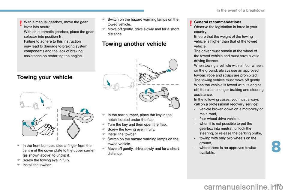
F In the front bumper, slide a finger from the
centre of the cover plate to the upper corner
(as shown above) to unclip it.
F
S
crew the towing eye in fully.
F
I
nstall the towbar. F
S
witch on the hazard warning lamps on the
towed vehicle.
F
M
ove off gently, drive slowly and for a short
distance. General recommendations
Obser ve the legislation in force in your
c o u nt r y.
Ensure that the weight of the towing
vehicle is higher than that of the towed
vehicle.
The driver must remain at the wheel of
the towed vehicle and must have a valid
driving licence.
When towing a vehicle with all four wheels
on the ground, always use an approved
towbar; rope and straps are prohibited.
The towing vehicle must move off gently.
When the vehicle is towed with its engine
off, there is no longer braking and steering
assistance.
In the following cases, you must always
call on a professional recovery ser vice:
-
v
ehicle broken down on a motor way or
main road,
-
f
our-wheel drive vehicle,
-
w
hen it is not possible to put the
gearbox into neutral, unlock the
steering, or release the parking brake,
-
t
owing with only two wheels on the
ground,
- w here there is no approved towbar
available.
F
I
n the rear bumper, place the key in the
notch located under the flap.
F
T
urn the key and then open the flap.
F
S
crew the towing eye in fully.
F
I
nstall the towbar.
F
S
witch on the hazard warning lamps on the
towed vehicle.
F M ove off gently, drive slowly and for a short
distance.
8
In the event of a breakdown
Page 210 of 312

208
Dimensions (mm)
These dimensions have been measured on an
unladen vehicle.
Your vehicle is available in two lengths
(Standard et Long).
The values may vary depending on wheel
diameters, load, engine, etc.Vehicle length
Standard (L1) Long (L2)
A Overall length 4,4034,753
B Overall height Standard version
1,79 6 to 1,825 1,812 to 1,820
Worksite version 1,8 4 0 to 1,8 6 0 1,8 49 to 1,8 6 0
C Wheelbase 2,7852,975
D Front overhang 892
E Rear overhang 726886
F Width with mirrors Folded
1,921
Unfolded 2 ,1 0 7
G Front track width 1,5 5 3 to 1,5 621,553
H Rear track width 1,5 6 8 to 1,57 7 1,5 49 to 1,5 6 8
Technical data
Page 211 of 312

209
Vehicle length
Standard (L1) Long (L2)
M Useable height of the opening 1,072
N Interior load height
(varies depending on the angle of the floor and the cur ve of
the roof) 1, 20 0 to 1, 270
O Loading sill height Standard version
548 to 588 X
Standard version with increased
payload 568 to 578 561 to 565
Commercial vehicle version 602 to 610 605 to 610
P Useable width of
the opening Without Multi-Flex bench seat
675
With Multi-Flex bench seat 6 41
Q Loading sill height Standard version
534 to 558
Standard version with increased
payload 551 to 558 543 to 552
Commercial vehicle version 574 to 581 575 to 587Vehicle length
Standard (L1) Long (L2)
I Interior width between wheel arches 1, 2 2 9
J Maximum interior
width Without sliding side door
1,73 3
With 1 sliding side door 1,6 3 0
With 2 sliding side doors 1,527
K Useable height of
the opening With side-hinged doors
1,13 7
With tailgate 1,1 9 7
L Useable width of the opening 1, 242
9
Technical data