Page 359 of 516

∙ The system is designed as an aid tothe driver in detecting large station-
ary objects to help avoid damaging
the vehicle. The system will not detect
small objects below the bumper, and
may not detect objects close to the
bumper or on the ground.
∙ If your vehicle sustains damage to the rear bumper fascia, leaving it mis-
aligned or bent, the sensing zone may
be altered causing inaccurate mea-
surement of obstacles or false alarms.
The RSS sounds a tone to warn the driver of
obstacles near the rear bumper when the
shif t lever is in R (Reverse). The system may
not detect objects at speeds above 3 mph
(5 km/h) and may not detect certain angu-
lar or moving objects.
The RSS detects obstacles up to 5.9 f t
(1.8 m) from the rear bumper with a de-
creased coverage area at the outer cor-
ners of the bumper (refer to the illustration
for approximate zone coverage areas). As
you move closer to the obstacle, the rate of
the tone increases. When the obstacle is
less than 10 in (25.0 cm) away, the tone will
sound continuously. If the RSS detects a
stationary or receding object further than
10 in (25.0 cm) from the side of the vehicle, the tone will sound for only 3 seconds.
Once the system detects an object ap-
proaching, the tone will sound again.
The RSS automatically turns on when the
shif t lever is placed in R (Reverse) and the
ignition is ON. The RSS OFF switch on the
instrument panel allows the driver to turn
the RSS on and off. To turn the RSS off, the
ignition must be on, and the shif t lever in R
(Reverse). An indicator light on the switch
will illuminate when the system is turned
off. If the indicator light illuminates when
the RSS is not turned off, it may indicate a
malfunction in the RSS.
Keep the RSS sensors (located on the rear
bumper fascia) free from snow, ice and
large accumulations of dirt (do not clean
the sensors with sharp objects). If the sen-
sors are covered, it will affect the accuracy
of the RSS.FREEING A FROZEN DOOR LOCK
To prevent a door lock from freezing, apply
de-icer through the key hole. If the lock
becomes frozen, heat the key before in-
serting it into the key hole or use the re-
mote keyless entry key fob (if so equipped).
ANTIFREEZE
In the winter when it is anticipated that the
temperature will drop below 32°F (0°C),
check the antifreeze to assure proper win-
ter protection. For additional information,
refer to “Engine cooling system” in the “Do-
it-yourself ” section of this manual.
BATTERY
This vehicle is equipped with a sealed
maintenance free battery. It is recom-
mended that you visit a NISSAN dealer for
service.
DRAINING OF COOLANT WATER
If the vehicle is to be lef t outside without
antifreeze, drain the cooling system, includ-
ing the engine block. Refill before operating
the vehicle. For additional information, refer
to “Changing engine coolant” in the “Do-it-
yourself ” section of this manual.
COLD WEATHER DRIVING
Starting and driving5-43
Page 361 of 516
ENGINE BLOCK HEATER (if so
equipped)
Engine block heaters are used to assist
with cold temperature starting.
The engine block heater should be used
when the outside temperature is 20°F (-7°C)
or lower.
Page 367 of 516
A. Blocks
B. Flat tire
Blocking wheels
Place suitable blocks at both the front and
back of the wheel diagonally opposite the
flat tire to prevent the vehicle from moving
when it is jacked up.
Page 371 of 516
∙ Do not start or run the engine whilevehicle is on the jack. It may cause the
vehicle to move. This is especially true
for vehicles with limited slip
differentials.
∙ Do not allow passengers to stay in the vehicle while it is on the jack.
∙ Never run the engine with a wheel(s) off the ground. It may cause the ve-
hicle to move.
Always refer to the illustration for the cor-
rect placement and jack-up points for your
specific vehicle model and jack type.
Carefully read the caution label attached
to the jack body and the following in-
structions. 1. Loosen each wheel nut 1 or 2 turns by
turning counterclockwise with the
wheel nut wrench. Do not remove the
wheel nuts until the tire is off the
ground.
Page 407 of 516
CAUTION
∙ Do not ground accessories directly tothe battery terminal. Doing so will by-
pass the variable voltage control sys-
tem and the vehicle battery may not
charge completely.
∙ Use electrical accessories with the en- gine running to avoid discharging the
vehicle battery.
Your vehicle is equipped with a variable
voltage control system. This system mea-
sures the amount of electrical discharge
from the battery and controls voltage gen-
erated by the generator. The current sensor
�Ais located near the
battery along the negative battery cable. If
you add electrical accessories to your ve-
hicle, be sure to ground them to a suitable
body ground such as the frame or engine
block area.
1. Power steering fluid pump pulley
2. Automatic belt tensioner pulley
3. Cooling fan pulley
4. Air conditioner compressor pulley
5. Crankshaf t pulley
6. Generator pulley
Page 416 of 516
Extended storage switch
If any electrical equipment does not oper-
ate, remove the extended storage switch
and check for an open fuse.
NOTE:
The extended storage switch is used for
long term vehicle storage. Even if the ex-
tended storage switch is broken it is not
necessary to replace it. Replace only the
open fuse in the switch with a new fuse.How to replace the extended storage
switch:
1. To remove the extended storage switch, be sure the ignition switch is in
the OFF or LOCK position.
2. Be sure the headlight switch is in the OFF position.
3. Remove the fuse box cover.
4. Pinch the locking tabs
�Afound on
each side of the storage switch.
5. Pull the storage switch straight out from the fuse box
�B.
Page 419 of 516

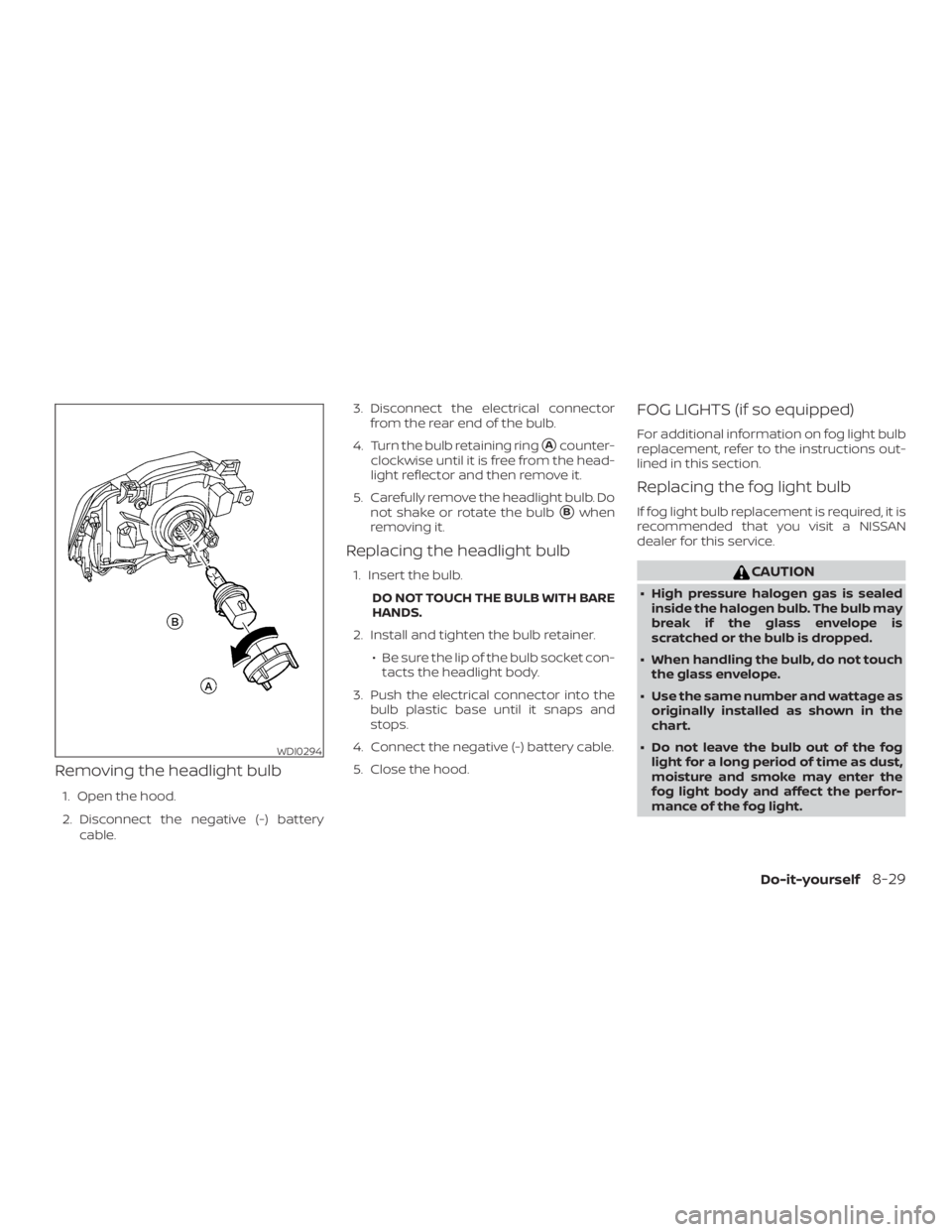
Removing the headlight bulb
1. Open the hood.
2. Disconnect the negative (-) batterycable. 3. Disconnect the electrical connector
from the rear end of the bulb.
4. Turn the bulb retaining ring
�Acounter-
clockwise until it is free from the head-
light reflector and then remove it.
5. Carefully remove the headlight bulb. Do not shake or rotate the bulb
�Bwhen
removing it.
Replacing the headlight bulb
1. Insert the bulb.
DO NOT TOUCH THE BULB WITH BARE
HANDS.
2. Install and tighten the bulb retainer. ∙ Be sure the lip of the bulb socket con-tacts the headlight body.
3. Push the electrical connector into the bulb plastic base until it snaps and
stops.
4. Connect the negative (-) battery cable.
5. Close the hood.
FOG LIGHTS (if so equipped)
For additional information on fog light bulb
replacement, refer to the instructions out-
lined in this section.
Replacing the fog light bulb
If fog light bulb replacement is required, it is
recommended that you visit a NISSAN
dealer for this service.
Page 456 of 516

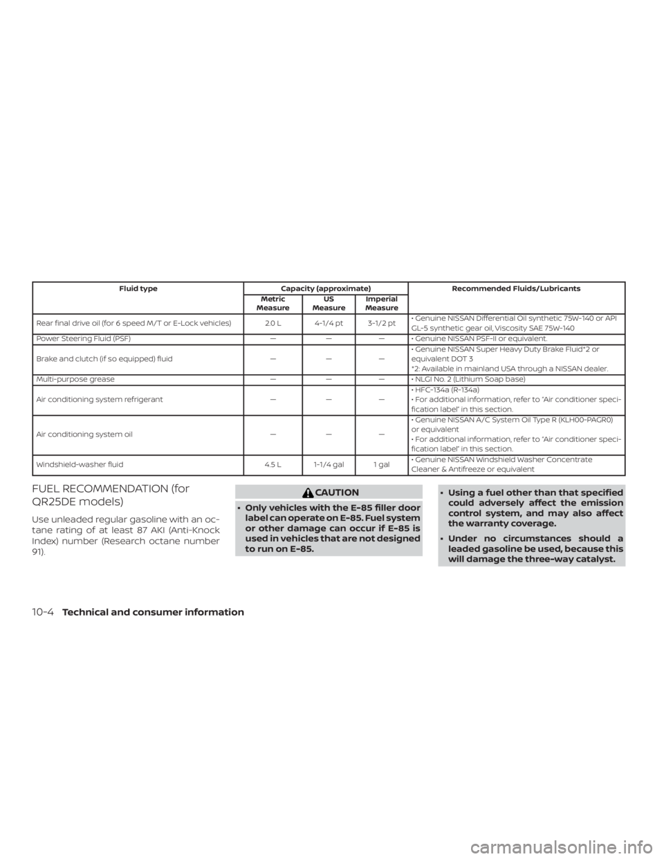
Fluid typeCapacity (approximate) Recommended Fluids/Lubricants
Metric
Measure US
Measure Imperial
Measure
Rear final drive oil (for 6 speed M/T or E-Lock vehicles) 2.0 L 4-1/4 pt 3-1/2 pt • Genuine NISSAN Differential Oil synthetic 75W-140 or API
GL-5 synthetic gear oil, Viscosity SAE 75W-140
Power Steering Fluid (PSF) ——— • Genuine NISSAN PSF-II or equivalent.
Brake and clutch (if so equipped) fluid ———• Genuine NISSAN Super Heavy Duty Brake Fluid*2 or
equivalent DOT 3
*2: Available in mainland USA through a NISSAN dealer.
Multi-purpose grease ——— • NLGI No. 2 (Lithium Soap base)
Air conditioning system refrigerant ———• HFC-134a (R-134a)
• For additional information, refer to “Air conditioner speci-
fication label” in this section.
Air conditioning system oil ———• Genuine NISSAN A/C System Oil Type R (KLH00-PAGR0)
or equivalent
• For additional information, refer to “Air conditioner speci-
fication label” in this section.
Windshield-washer fluid 4.5 L 1-1/4 gal 1 gal• Genuine NISSAN Windshield Washer Concentrate
Cleaner & Antifreeze or equivalent
FUEL RECOMMENDATION (for
QR25DE models)
Use unleaded regular gasoline with an oc-
tane rating of at least 87 AKI (Anti-Knock
Index) number (Research octane number
91).