Page 66 of 516
WARNING
∙ The three-point seat belt with Auto-matic Locking Retractor (ALR) must be
used when installing a child restraint.
Failure to use the ALR mode will result
in the child restraint not being prop-
erly secured. The restraint could tip
over or be loose and cause injury to a
child in a sudden stop or collision.
Also, it can change the operation of
the front passenger air bag. For addi-
tional information, refer to “Front pas-
senger air bag and status light” in this
section.
∙ A child restraint system will not be in- stalled properly and the child could be
seriously injured or killed in a sudden
stop or collision.
– Never install a rear-facing child re- straint system on the driver’s side
jump seat.
– Do not install a child restraint sys- tem on the passenger’s side jump
seat without unfolding the seat
extender.
Page 73 of 516
 follow
these steps.1")
1. Top tether strap
2. Tether strap
3. Tether anchor point
Before securing the child restraint with the
LATCH lower anchors (rear outboard seat-
ing positions for Crew Cab models) follow
these steps.1. If necessary, raise or remove the head restraint/headrest to position the top
tether strap as shown. If the head
restraint/headrest is removed, store it
in a secure place. Be sure to reinstall the
head restraint/headrest when the child
restraint is removed. For additional in-
formation, refer to “Head
restraints/headrests” in this section.
2. Position the top tether strap as shown.
3. Secure the tether strap to the tether anchor point as shown.
4. Return the seatback to the locked po- sition.
5. Refer back to child restraint installation steps before tightening the tether
strap.
If you have any questions when install-
ing a top tether strap, it is recommended
that you visit a NISSAN dealer for this
service.
FORWARD-FACING CHILD
RESTRAINT INSTALLATION USING
LATCH — JUMP SEAT (King Cab®
models)
Page 83 of 516
First, secure the child restraint with the seat
belt.1. If necessary, raise or remove the head restraint/headrest to position the top
tether strap as shown. If the head
restraint/headrest is removed, store it
in a secure place. Be sure to reinstall the
head restraint/headrest when the child
restraint is removed. For additional in-
formation, refer to “Head
restraints/headrests” in this section.
2. Position the top tether strap as shown.
3. Secure the tether strap to the tether anchor point as shown.
4. Return the seatback to the locked po- sition.
5. Refer back to child restraint installation steps before tightening the tether
strap.
If you have any questions when install-
ing a top tether strap, it is recommended
that you visit a NISSAN dealer for this
service.
FORWARD-FACING CHILD
RESTRAINT INSTALLATION USING
THE SEAT BELTS — FRONT
PASSENGER AND JUMP SEATS
(King Cab® models)
Page 113 of 516
Repair and replacement
procedure
The front air bags, side air bags, curtain air
bags and pretensioner(s) are designed to
inflate on a one-time-only basis. As a re-
minder, unless it is damaged, the supple-
mental air bag warning light remains illu-
minated af ter inflation has occurred. These
systems should be repaired and/or re-
placed as soon as possible. It is recom-
mended that you visit a NISSAN dealer for
this service.
When maintenance work is required on the
vehicle, the front air bags, side air bags,
curtain air bags, pretensioner(s) and re-
lated parts should be pointed out to the
person performing the maintenance. The
ignition switch should always be placed in
the LOCK position when working under the
hood or inside the vehicle.
Page 130 of 516
If the ABS warning light illuminates while
the engine is running or while driving, it
may indicate the ABS is not functioning
properly. Have the system checked. It is
recommended that you visit a NISSAN
dealer for this service.
If an ABS malfunction occurs, the anti-lock
function is turned off. The brake system
then operates normally but without anti-
lock assistance. For additional information,
refer to “Brake system” in the “Starting and
driving” section of this manual.
Page 151 of 516
The E-Lock system can help provide added
traction if the vehicle is stuck or becoming
stuck.
To activate the E-Lock system:∙ The 4WD switch must be in the 4LO po- sition (4-Wheel Drive vehicles),
∙ The vehicle must be stopped or moving at 4 mph (7 km/h) or less, and
∙ The E-Lock system switch must be turned on. When the E-Lock switch is turned on, the
indicator light will flash until the system
engages. However, if all operation condi-
tions listed above are not met or the sys-
tem becomes disengaged, the indicator
light will continue to flash.
The Anti-lock Braking System (ABS) is dis-
abled and the ABS light illuminates when
the E-Lock system is on. Also, the Vehicle
Dynamic Control (VDC) system is disabled
and the VDC light illuminates when the
E-Lock system is on.
For additional information, refer to “Elec-
tronic locking rear differential (E-Lock) sys-
tem” in the “Starting and driving” section of
this manual for further explanation and
system limitations.
Page 152 of 516

WARNING
Pay special attention to your surround-
ings when using the clutch interlock
switch. The vehicle will move forward or
backward according to the gear
selected.
The clutch interlock (clutch start) switch
allows for starting the engine without de-
pressing the clutch pedal. This feature
helps you restart the engine if it stops un-
der difficult conditions. (For example, the
engine stops on a steep hill and a slight
movement forward or backward might be
dangerous.) To use the clutch interlock switch:
1. Set the parking brake.
2. Depress the brake pedal with your right foot.
3. Place your lef t foot on the brake pedal and release the parking brake.
4. Turn the ignition switch to the ON posi- tion.
5. Push and release the clutch interlock switch. The CANCEL light on the switch
will illuminate.
6. Turn the ignition to the START position to start the engine and, at the same
time, depress the accelerator pedal
with your right foot. As the vehicle be-
gins to move, take your lef t foot off the
brake. Once the engine has started, the
clutch interlock switch CANCEL light
shuts off. Do not use the interlock
switch to start the engine under nor-
mal driving conditions.
Page 157 of 516
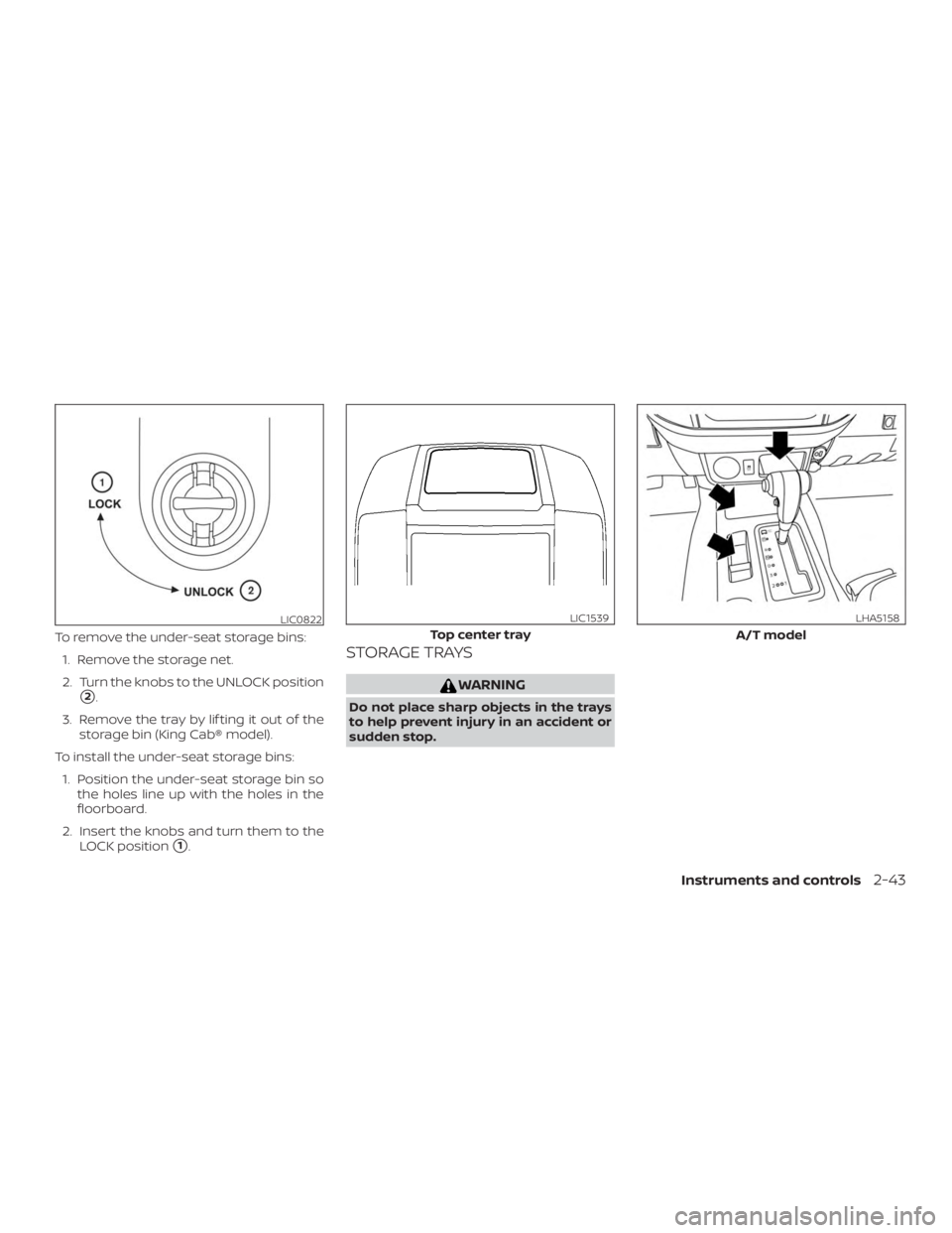
To remove the under-seat storage bins:1. Remove the storage net.
2. Turn the knobs to the UNLOCK position
�2.
3. Remove the tray by lif ting it out of the storage bin (King Cab® model).
To install the under-seat storage bins: 1. Position the under-seat storage bin so the holes line up with the holes in the
floorboard.
2. Insert the knobs and turn them to the LOCK position
�1.
STORAGE TRAYS
 must be
used when installing a child restraint.
Failure to use the ALR mode will result
in the child restraint not being p")

 are designed to
inflate on a one-time-only basis. As a re-
minder, unless it is damaged, the su")

,
�")