2019 NISSAN ARMADA instrument panel
[x] Cancel search: instrument panelPage 135 of 536
SIC4378
INSTRUMENT BRIGHTNESS CON-
TROL
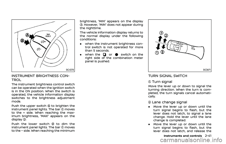
The instrument brightness control switch
can be operated when the ignition switch
is in the ON position. When the switch is
operated, the vehicle information display
switches to the brightness adjustment
mode.
Push the upper switch
to brighten the
instrument panel lights. The barmoves
to the + side. When reaching the max-
imum brightness, “MAX” appears on the
display
.
Push the lower switch
to dim the
instrument panel lights. The barmoves
to the − side. When reaching the minimum brightness, “MIN” appears on the display
. However, “MIN” does not appear during
the nighttime.
The vehicle information display returns to
the normal display under the following
conditions:
. when the instrument brightness con-
trol switch is not operated for more
than 5 seconds.
. when the
orswitch on the
right side of the combination meter
panel is pushed.
SIC3671
TURN SIGNAL SWITCH
Turn signal
Move the lever up or down to signal the
turning direction. When the turn is com-
pleted, the turn signals cancel automati-
cally.
Lane change signal
. Move the lever up or down until the
turn signal begins to flash, but the
lever does not latch, to signal a lane
change. Hold the lever until the lane
change is completed.
. Move the lever up or down until the
turn signal begins to flash, but the
lever does not latch, and release the
Instruments and controls2-41
Page 138 of 536
2-44Instruments and controls
.Any liquid spilled on the heated
seat should be removed immedi-
ately with a dry cloth.
. When cleaning the seat, never use
gasoline, thinner, or any similar
materials.
. If any malfunctions are found or
the heated seat does not operate,
turn the switch off and have the
system checked. It is recom-
mended you visit a NISSAN dealer
for this service.
SIC2770
FRONT (if so equipped)
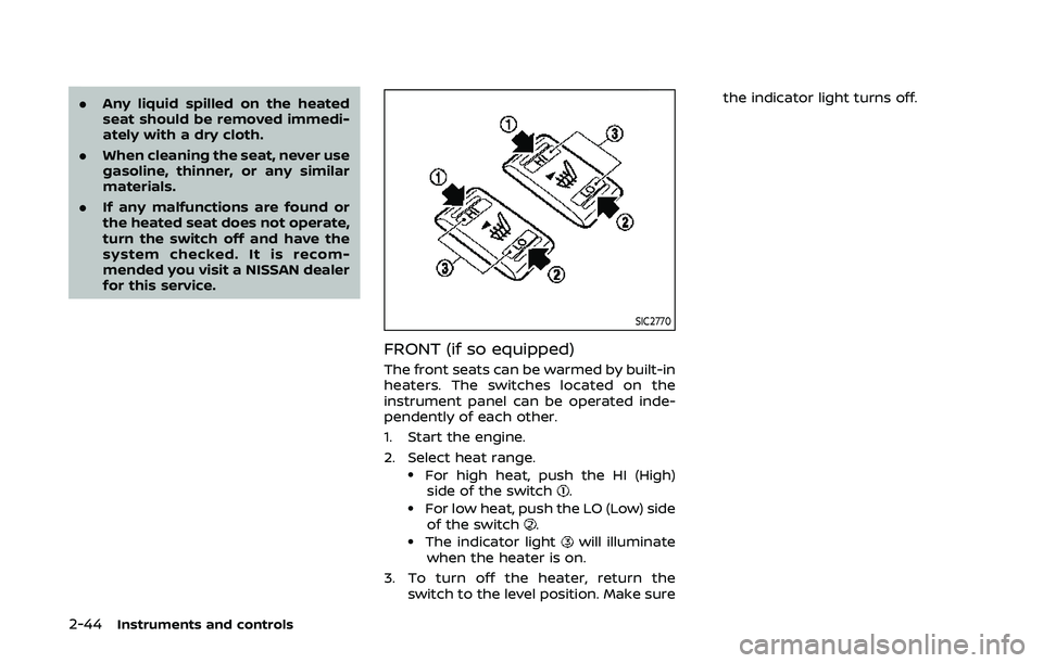
The front seats can be warmed by built-in
heaters. The switches located on the
instrument panel can be operated inde-
pendently of each other.
1. Start the engine.
2. Select heat range.
.For high heat, push the HI (High)
side of the switch..For low heat, push the LO (Low) sideof the switch..The indicator lightwill illuminate
when the heater is on.
3. To turn off the heater, return the switch to the level position. Make sure the indicator light turns off.
Page 139 of 536
SIC2770
REAR (if so equipped)
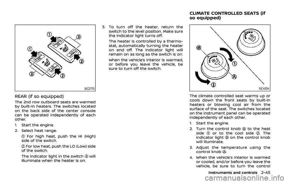
The 2nd row outboard seats are warmed
by built-in heaters. The switches located
on the back side of the center console
can be operated independently of each
other.
1. Start the engine.
2. Select heat range.
For high heat, push the HI (High)
side of the switch.
For low heat, push the LO (Low) side
of the switch.
The indicator light in the switch
will
illuminate when the heater is on. 3. To turn off the heater, return the
switch to the level position. Make sure
the indicator light turns off.
The heater is controlled by a thermo-
stat, automatically turning the heater
on and off. The indicator light will
remain on as long as the switch is on.
When the vehicle’s interior is warmed,
or before you leave the vehicle, be
sure to turn off the switch.
SIC4334
The climate controlled seat warms up or
cools down the front seats by built-in
heaters or blowing cool air from the
surface of the seat. The switches located
on the instrument panel can be operated
independently of each other.
1. Start the engine.
2. Turn the control knob
to the heat
sideor to the cool side. The
indicator lighton the control knob
will illuminate.
3. Adjust the temperature using the control knob
.
4. When the vehicle’s interior is warmed or cooled, and/or before you leave the
vehicle, be sure to turn the control
Instruments and controls2-45
CLIMATE CONTROLLED SEATS (if
so equipped)
Page 146 of 536
2-52Instruments and controls
CAUTION
.Use power outlet with the engine
running to avoid discharging the
vehicle battery.
. Avoid using power outlet when
the air conditioner, headlights or
rear window defroster is on.
. Before inserting or disconnecting
a plug, be sure the electrical
accessory being used is turned
OFF.
. When not in use, be sure to close
the cap. Do not allow water or any
liquid to contact the outlet.
SIC4389
Instrument panel
SIC4456Back side of front console
SIC4391
Luggage room
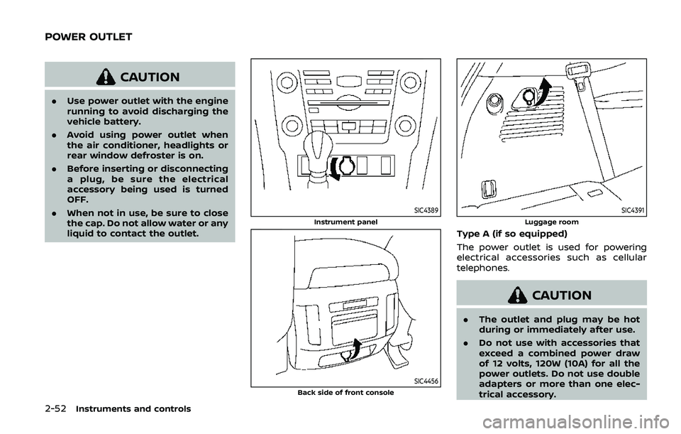
Type A (if so equipped)
The power outlet is used for powering
electrical accessories such as cellular
telephones.
CAUTION
.The outlet and plug may be hot
during or immediately after use.
. Do not use with accessories that
exceed a combined power draw
of 12 volts, 120W (10A) for all the
power outlets. Do not use double
adapters or more than one elec-
trical accessory.
POWER OUTLET
Page 186 of 536
3-12Pre-driving checks and adjustments
CAUTION
The lockout protection may not
function under the following condi-
tions:
.When the Intelligent Key is placed
on top of the instrument panel.
. When the Intelligent Key is placed
inside the glove box or a storage
bin.
. When the Intelligent Key is placed
inside the door pockets.
. When the Intelligent Key is placed
inside or near metallic materials.
Unlocking doors and fuel-filler door
1. Push the door handle request switch
(driver’s or front passenger’s)or the
liftgate request switchonce while
carrying the Intelligent Key with you.
When you approach the vehicle with
the Intelligent Key, the puddle light
and the passenger cabin illumination
will illuminate and stay on for a short
period of time (if so equipped). (See
“Welcome light” (P.2-68).)
2. The hazard indicator flashes once and outside chime sounds once. The cor-
responding door will unlock. The fuel-filler door will also unlock
when the driver’s door handle request
switch is pushed.
3. Push the door handle request switch again within 60 seconds.
4. The hazard indicator flashes once and outside chime sounds once again. All
the doors will unlock.
The liftgate can be unlocked and opened
by pushing the liftgate opener switch. See
“Liftgate” (P.3-22).
All doors will be locked automatically
unless one of the following operations is
performed within 1 minute after pushing
the request switch while the doors are
locked. If during this 1-minute time period,
the request switch is pushed, all doors will
be locked automatically after another 1
minute.
. Opening any door
. Pushing the ignition switch
Power liftgate open (if so equipped)
1. Carry the Intelligent Key.
2. Push the power liftgate opener switch
.
3. The liftgate will unlock and automati- cally open.
4. The hazard indicator flashes 4 times and the outside chime sounds.
BATTERY SAVER SYSTEM
When all the following conditions are met
for a period of time, the battery saver
system will cut off the power supply to
prevent battery discharge.
.The ignition switch is in the ACC
position, and
. All doors are closed, and
. The shift lever is in the P (Park)
position.
WARNING SIGNALS
To help prevent the vehicle from moving
unexpectedly by erroneous operation of
the Intelligent Key listed on the following
chart or to help prevent the vehicle from
being stolen, chime or beep sounds inside
and outside the vehicle and a warning
displays in the vehicle information display.
When a chime or beep sounds or the
warning displays, be sure to check the
vehicle and Intelligent Key.
See “Troubleshooting guide” (P.3-13) and
“Vehicle information display” (P.2-20).
Page 195 of 536
.The remote engine startbutton is
not pushed and held within 5 seconds
of pushing the “LOCK”
button.
. The brake pedal is depressed.
. The doors are not closed and locked.
. The liftgate is open.
. The Intelligent Key system warning
light remains on in the vehicle infor-
mation display.
. An Intelligent Key is left inside the
vehicle.
. The theft alarm sounds due to illegal
entry into the vehicle.
. Two remote engine starts, or a single
remote engine start with an exten-
sion, have already been used.
. The shift lever is not in the P (Park)
position.
The remote engine start may display a
warning or indicator in the vehicle infor-
mation display. For an explanation of the
warning or indicator, see “Operational
indicators” (P.2-23).
JVP0463X
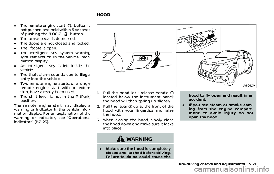
1. Pull the hood lock release handlelocated below the instrument panel;
the hood will then spring up slightly.
2. Pull the lever
up at the front of the
hood with your fingertips and raise
the hood.
3. When closing the hood, slowly close the hood down and make sure it locks
into place.
WARNING
.Make sure the hood is completely
closed and latched before driving.
Failure to do so could cause the hood to fly open and result in an
accident.
. If you see steam or smoke com-
ing from the engine compart-
ment, to avoid injury do not
open the hood.
Pre-driving checks and adjustments3-21
HOOD
Page 197 of 536
SPA2547
Power liftgate main switch
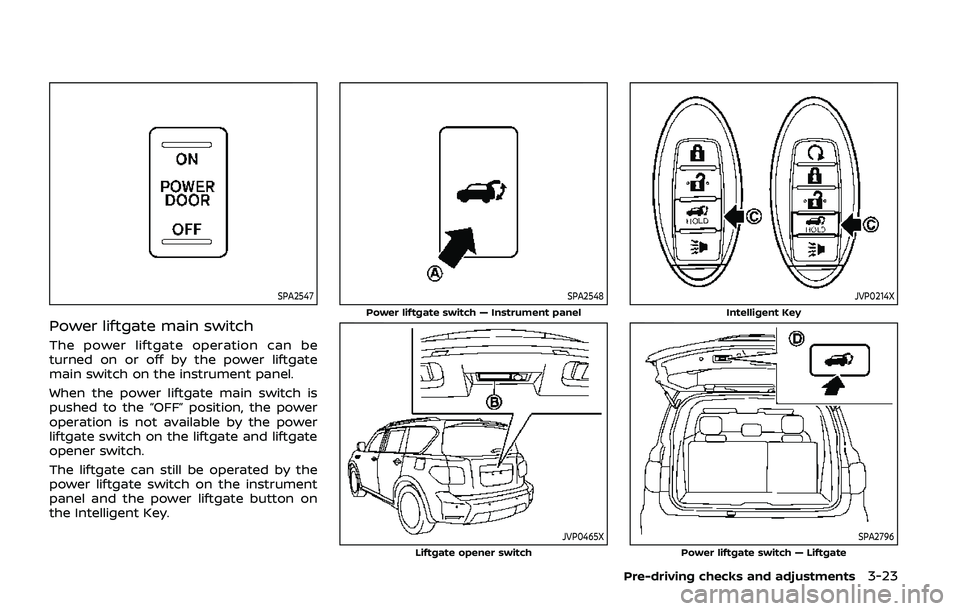
The power liftgate operation can be
turned on or off by the power liftgate
main switch on the instrument panel.
When the power liftgate main switch is
pushed to the “OFF” position, the power
operation is not available by the power
liftgate switch on the liftgate and liftgate
opener switch.
The liftgate can still be operated by the
power liftgate switch on the instrument
panel and the power liftgate button on
the Intelligent Key.
SPA2548
Power liftgate switch — Instrument panel
JVP0465XLiftgate opener switch
JVP0214X
Intelligent Key
SPA2796Power liftgate switch — Liftgate
Pre-driving checks and adjustments3-23
Page 198 of 536
3-24Pre-driving checks and adjustments
Power open
When the liftgate is fully closed, the
liftgate will fully open automatically by:
.pushing the power liftgate switch
on the instrument panel
. pushing the liftgate opener switch
.pushing the power liftgate buttonon the Intelligent Key for more than 1
second
The hazard flashes 4 times and the out-
side chime sounds when the liftgate
starts opening.
NOTE:
The liftgate can be opened by the
power liftgate switch
, the liftgate
opener switchor the power liftgate
buttoneven if the liftgate is
locked. The liftgate will individually un-
lock and open.
Power close
When the liftgate is fully opened, the
liftgate will fully close automatically by:
. pushing the power liftgate switch
on the instrument panel
. pushing the power liftgate button
on the Intelligent Key for more than 1
second
. pushing the power liftgate switch
on the lower part of the liftgate
The hazard flashes 4 times and the out- side chime sounds when the liftgate
starts closing.
NOTE:
When the liftgate is closed, it remains
unlocked. Manually lock the liftgate.
Reverse function
The power liftgate will reverse immedi-
ately if one of the following actions is
performed during power open or power
close.
.
pushing the power liftgate switch
on the instrument panel
. pushing the power liftgate button
on the Intelligent Key.
. pushing the liftgate switch
on the
lower part of the liftgate
The outside chime sounds when the
liftgate starts to reverse.
Auto reverse function
The auto-reverse function enables the
liftgate to automatically reverse when
something is caught in the liftgate as it
is opening or closing. When the control
unit detects an obstacle, the liftgate will
reverse and return to the full open or full
close position.
If a second obstacle is detected, the
liftgate motion will stop and the drive
motor will disengage. The liftgate will
enter the manual mode. A pinch sensor is mounted on each side
of the liftgate. If an obstacle is detected
by the pinch sensor during power close,
the liftgate will reverse and return to the
full open position immediately.
NOTE:
If the pinch sensor is damaged or
removed, the power close function will
not operate.
WARNING
There is a small distance immedi-
ately before the closed position that
cannot be detected. Make sure that
all passengers keep their hands, etc.,
clear from the liftgate opening be-
fore closing the liftgate.
Manual mode
If power operation is not available, the
liftgate can be operated manually. Power
operation may not be available if multiple
obstacles have been detected in a single
power cycle or if the battery voltage is
low. When the power liftgate main switch
is in the OFF position, the liftgate can be
opened manually by pushing the liftgate
opener switch. If the power liftgate open-
er switch is pushed during power open or
close, the power operation will be can-