2019 NISSAN ARMADA oil temperature
[x] Cancel search: oil temperaturePage 17 of 536
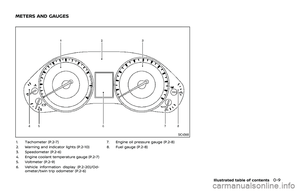
SIC4368
1. Tachometer (P.2-7)
2. Warning and indicator lights (P.2-10)
3. Speedometer (P.2-6)
4. Engine coolant temperature gauge (P.2-7)
5. Voltmeter (P.2-9)
6. Vehicle information display (P.2-20)/Od-ometer/twin trip odometer (P.2-6) 7. Engine oil pressure gauge (P.2-8)
8. Fuel gauge (P.2-8)
Illustrated table of contents0-9
METERS AND GAUGES
Page 19 of 536

Warninglight Name
Page
Anti-lock Braking System
(ABS) warning light 2-11
Automatic Emergency
Braking (AEB) system
warning light2-11
Automatic Transmission
(AT) check warning light
2-11
Automatic Transmission
(AT) oil temperature warn-
ing light2-11
Automatic Transmission
(AT) park warning light
2-12
Blind Spot Warning (BSW)/
Intelligent Blind Spot Inter-
vention (I-BSI) system
warning light (orange; if so
equipped)2-12
Brake warning light
2-12
Charge warning light2-13
Intelligent Distance Control
(I-DC) system warning light
(orange; if so equipped)2-13
Engine oil pressure warning
light
2-13
Four-Wheel Drive (4WD)
warning light (4WD models)2-14Warning
light Name
Page
Intelligent Cruise Control
(ICC) system warning light
(orange) 2-14
Intelligent Key warning
light
2-14
Lane Departure Warning
(LDW) indicator light (or-
ange; if so equipped)2-14
Low tire pressure warning
light
2-15
Master warning light
2-16
Seat belt warning light2-16
Supplemental air bag
warning light 2-17
Vehicle Dynamic Control
(VDC) warning light2-17Indica-
tor light Name
Page
Automatic Transmission
(AT) position indicator light 2-18
Intelligent Blind Spot Inter-
vention (I-BSI) ON indicator
light (green; if so equipped)2-18
Check suspension indicator
light
2-18
Exterior light indicator
2-18
Front fog light indicator
light (if so equipped)2-18
Front passenger air bag
status light2-18
High beam indicator light
2-18
Intelligent Lane Interven-
tion (I-LI) ON indicator light
(green; if so equipped)2-18
Malfunction Indicator Light
(MIL)
2-18
Security indicator light
2-19
SNOW mode indicator light2-19
TOW mode indicator light2-19
Turn signal/hazard indica-
tor lights2-19
Vehicle Dynamic Control
(VDC) off indicator light2-20
Illustrated table of contents0-11
WARNING AND INDICATOR LIGHTS
Page 95 of 536
2 Instruments and controls
Cockpit ........................................................................\
.......................... 2-3
Instrument panel ........................................................................\
.. 2-4
Meters and gauges ..................................................................... 2-5Speedometer and odometer ........................................ 2-6
Tachometer ........................................................................\
........ 2-7
Engine coolant temperature gauge ....................... 2-7
Fuel gauge ........................................................................\
........... 2-8
Engine oil pressure gauge .............................................. 2-8
Voltmeter ........................................................................\
.............. 2-9
Meter/ring illumination and needle sweep ....... 2-9
Warning lights, indicator lights and
audible reminders ..................................................................... 2-10 Checking lights ..................................................................... 2-11
Warning lights ........................................................................\
2-11
Indicator lights ...................................................................... 2-17
Audible reminders .............................................................. 2-20
Vehicle information display ............................................... 2-20 Operational indicators .................................................... 2-23
Maintenance indicators ................................................. 2-26
Trip computer ........................................................................\
2-28
Security systems ........................................................................\
2-30 Vehicle Security System ................................................ 2-30
NISSAN Vehicle Immobilizer System .................... 2-32 Wiper and washer switch ................................................... 2-33
Windshield wiper and washer operation ...... 2-34
Rain-sensing auto wiper system (if
so equipped) ........................................................................\
. 2-34
Rear window wiper and
washer operation ............................................................. 2-36
Rear window and outside mirror
(if so equipped) defroster switch ................................. 2-36
Windshield deicer switch (if so equipped) ............. 2-36
Headlight and turn signal switch ................................ 2-37 Headlight switch ............................................................... 2-37
Instrument brightness control .............................. 2-41
Turn signal switch ........................................................... 2-41
Fog light switch (if so equipped) ......................... 2-42
Heated steering wheel (if so equipped) .................. 2-42
Horn ........................................................................\
............................. 2-43
Heated seats ........................................................................\
......... 2-43 Front (if so equipped) .................................................... 2-44
Rear (if so equipped) ...................................................... 2-45
Climate controlled seats (if so equipped) ............. 2-45
Warning systems switch (if so equipped) ............. 2-46
SNOW mode switch ................................................................ 2-47
TOW mode switch .................................................................... 2-47
Vehicle Dynamic Control (VDC) OFF switch ........ 2-48
Page 99 of 536
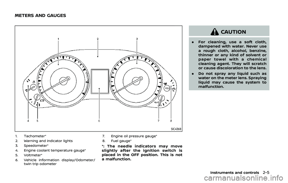
SIC4368
1. Tachometer*
2. Warning and indicator lights
3. Speedometer*
4. Engine coolant temperature gauge*
5. Voltmeter*
6. Vehicle information display/Odometer/twin trip odometer 7. Engine oil pressure gauge*
8. Fuel gauge*
*: The needle indicators may move
slightly after the ignition switch is
placed in the OFF position. This is not
a malfunction.
CAUTION
.
For cleaning, use a soft cloth,
dampened with water. Never use
a rough cloth, alcohol, benzine,
thinner or any kind of solvent or
paper towel with a chemical
cleaning agent. They will scratch
or cause discoloration to the lens.
. Do not spray any liquid such as
water on the meter lens. Spraying
liquid may cause the system to
malfunction.
Instruments and controls2-5
METERS AND GAUGES
Page 105 of 536
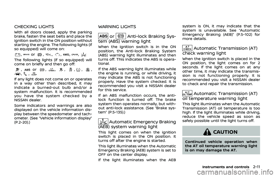
CHECKING LIGHTS
With all doors closed, apply the parking
brake, fasten the seat belts and place the
ignition switch in the ON position without
starting the engine. The following lights (if
so equipped) will come on:
,or,,,,,
The following lights (if so equipped) will
come on briefly and then go off:
,or,,,,,,,,
If any light does not come on or operates
in a way other than described, it may
indicate a burned-out bulb and/or a
system malfunction. It is recommended
you have the system checked by a
NISSAN dealer.
Some indicators and warnings are also
displayed on the vehicle information dis-
play between the speedometer and tach-
ometer. (See “Vehicle information display”
(P.2-20).)
WARNING LIGHTS
orAnti-lock Braking Sys-
tem (ABS) warning light
When the ignition switch is in the ON
position, the Anti-lock Braking System
(ABS) warning light illuminates and then
turns off. This indicates the ABS is opera-
tional.
If the ABS warning light illuminates while
the engine is running, or while driving, it
may indicate the ABS is not functioning
properly. Have the system checked. It is
recommended you visit a NISSAN dealer
for this service.
If an ABS malfunction occurs, the anti-
lock function is turned off. The brake
system then operates normally, but with-
out anti-lock assistance. (See “Brake sys-
tem” (P.5-135).)
Automatic Emergency Braking
(AEB) system warning light
This light comes on when the ignition
switch is placed in the ON position. It
turns off after the engine is started.
This light illuminates when the Automatic
Emergency Braking (AEB) system is set to
OFF on the center display.
If the light illuminates when the AEB system is ON, it may indicate that the
system is unavailable. See “Automatic
Emergency Braking (AEB)” (P.5-102) for
more details.
Automatic Transmission (AT)
check warning light
When the ignition switch is placed in the
ON position, the light comes on for 2
seconds. If the light comes on at any
other time, it may indicate the transmis-
sion is not functioning properly. It is
recommended you visit a NISSAN dealer
to check and repair the transmission.
Automatic Transmission (AT)
oil temperature warning light
This light illuminates when the Automatic
Transmission (AT) oil temperature is too
high. If the light illuminates while driving,
reduce the vehicle speed as soon as
safely possible until the light turns off.
CAUTION
Continued vehicle operation when
the AT oil temperature warning light
is on may damage the AT.
Instruments and controls2-11
Page 123 of 536

warning feature. If the fuel level is low, the
warning is displayed on the screen.
When the fuel level drops even lower, the
dte display will change to “——”.
.If the amount of fuel added is small,
the display just before the ignition
switch is pushed to the OFF position
may continue to be displayed.
. When driving uphill or rounding
curves, the fuel in the tank shifts,
which may momentarily change the
display.
5. Outside air temperature (ICY — °F
or °C)
The outside air temperature is displayed
in °F or °C in the range of −22 to 131°F (−30
to 55°C).
The outside air temperature mode in-
cludes a low temperature warning fea-
ture. If the outside air temperature is
below 37°F (3°C), the warning is displayed
on the screen.
The outside temperature sensor is lo-
cated in front of the radiator. The sensor
may be affected by road or engine heat,
wind directions and other driving condi-
tions. The display may differ from the
actual outside temperature or the tem-
perature displayed on various signs or
billboards.
6. Setting
Setting is available while the engine is
running.
Setting cannot be made while driving. A
message “SETTING CAN ONLY BE OPER-
ATED WHEN STOPPED” is also displayed
on the vehicle information display.
The
switchandswitchare
used in the setting mode to select and
decide a menu.
SKIP:
Push the
switchto move to the
warning check mode.
Push the
switchto select other
menus.
ALERT:
There are 3 submenus under the alert
menu.
. BACK
Select this submenu to return to the
top page of the setting mode.
. TIMER
Select this submenu to specify when
the “TIMER” indicator activates.
. ICY
Select this submenu to display the low
outside temperature warning. MAINTENANCE:
There are 5 submenus under the main-
tenance menu.
. BACK
Select this submenu to return to the
top page of the setting mode.
. TIRE
Select this submenu to set or reset the
distance for replacing tires.
. FILTER
Select this submenu to set or reset the
distance for replacing the oil filter.
. OIL
Select this submenu to set or reset the
distance for changing the engine oil.
. OTHER
Select this submenu and set or reset
the distance for replacing items other
than the engine oil, oil filter and tires.
OPTIONS:
There are 4 submenus under the display
menu.
. BACK
Select this submenu to return to the
top page of the setting mode.
. LANGUAGE
Select this submenu to choose Eng-
lish, French or Spanish for display.
Instruments and controls2-29
Page 278 of 536
5-18Starting and driving
If:
1. The engine coolant temperature is notreduced.
2. The air conditioning cooling function does not turn back ON.
3. The engine oil pressure warning light
illuminates or engine coolant
temperature gauge does not return
to the normal range from the H
position, this may indicate a malfunc-
tion. Move the vehicle off the road to a
safe area and allow the engine to cool.
If after checking the oil and coolant,
the
remains on or engine coolant
temperature does not return to the
normal range, do not continue to
drive. It is recommended you contact
a NISSAN dealer.
The Malfunction Indicator Light (MIL)
may also come ON. You do not need to
have your vehicle towed, unless it re-
mains on, but have it inspected soon. It is
recommended you contact a NISSAN
dealer for this service. See “Warning lights,
indicator lights and audible reminders”
(P.2-10).
WARNING
Overheating can result in reduced
engine power and vehicle speed.
The reduced speed may be lower
than other traffic, which could in-
crease the chance of a collision. Be
especially careful when driving. If the
vehicle cannot maintain a safe driv-
ing speed, pull to the side of the road
in a safe area. Allow the engine to
cool and return to normal operation.
See “If your vehicle overheats” (P.6-
14).
CAUTION
Running the engine with the engine
oil pressure warning light on could
cause serious damage to the engine
almost immediately. Such damage is
not covered by warranty. Turn off the
engine as soon as it is safe to do so.
AUTOMATIC TRANSMISSION
7 speed automatic transmission
The automatic transmission in your vehi-
cle is electronically controlled by a trans-
mission control module to produce
maximum efficiency and smooth opera-
tion.
Shown on the following pages are the
recommended operating procedures for
this transmission. Follow these proce-
dures for maximum vehicle performance
and driving enjoyment.
Starting the vehicle
After starting the engine, fully depress the
foot brake pedal and push the shift lever
button before shifting the shift lever to
the R (Reverse), N (Neutral), D (Drive) or
Manual shift mode position. Be sure the
vehicle is fully stopped before attempting
to shift the shift lever.
This automatic transmission model is
designed so that the foot brake pedal
must be depressed before shifting from
P (Park) to any drive position while the
ignition switch position is ON.
The shift lever cannot be moved out of
the P (Park) position and into any of the
other gear positions if the ignition
switch is pushed to the LOCK, OFF or
ACC position.
Page 381 of 536
7. Avoid idling..Shutting off your engine when safefor stops exceeding 30-60 seconds
saves fuel and reduces emissions.
8. Buy an automated pass for toll roads.
.Automated passes permit drivers to use special lanes to maintain cruis-
ing speed through the toll and
avoid stopping and starting.
9. Winter warm up.
.Limit idling time to minimize impact to fuel economy.
.Vehicles typically need no morethan 30 seconds of idling at start-
up to effectively circulate the en-
gine oil before driving.
.Your vehicle will reach its ideal
operating temperature more
quickly while driving versus idling.
10. Keeping your vehicle cool.
.Park your vehicle in a covered parking area or in the shade when-
ever possible.
.When entering a hot vehicle, open- ing the windows will help to reduce
the inside temperature faster, re-
sulting in reduced demand on your
A/C system. .
Keep your engine tuned up.
. Follow the recommended scheduled
maintenance.
. Keep the tires inflated to the correct
pressure. Low tire pressure increases
tire wear and lowers fuel economy.
. Keep the wheels in correct alignment.
Improper alignment increases tire
wear and lowers fuel economy.
. Use the recommended viscosity en-
gine oil. (See “Engine oil and oil filter
recommendation” (P.10-5).)
WARNING
. Do not attempt to raise two
wheels off the ground and shift
the transmission to any drive or
reverse position with the engine
running. Doing so may result in
drivetrain damage or unexpected
vehicle movement which could
result in serious vehicle damage
or personal injury.
. Do not attempt to test a 4WD
equipped vehicle on a 2-wheel
dynamometer or similar equip-
ment even if the other two
wheels are raised off the ground.
Make sure you inform test facility
personnel that your vehicle is
equipped with 4WD before it is
placed on a dynamometer. Using
the wrong test equipment may
result in drivetrain damage or
unexpected vehicle movement
which could result in serious ve-
hicle damage or personal injury.
Starting and driving5-121
INCREASING FUEL ECONOMYNISSAN ALL-MODE 4WD® (if so equipped)