2019 NISSAN ARMADA light
[x] Cancel search: lightPage 237 of 536
INTELLIGENT AROUND VIEW MONI-
TOR SYSTEM LIMITATIONS
WARNING
Listed below are the system limita-
tions for Intelligent Around View
Monitor. Failure to operate the vehi-
cle in accordance with these system
limitations could result in serious
injury or death.
.Do not use the Intelligent Around
View Monitor with the outside
mirrors in the stored position,
and make sure that the liftgate
is securely closed when operating
the vehicle using the Intelligent
Around View Monitor.
. The apparent distance between
objects viewed on the Intelligent
Around View Monitor differs from
the actual distance.
. The cameras are installed on the
front grille, the outside mirrors
and above the rear license plate.
Do not put anything on the vehi-
cle that covers the cameras.
. When washing the vehicle with
high pressure water, be sure not
to spray it around the cameras. Otherwise, water may enter the
camera unit causing water con-
densation on the lens, a malfunc-
tion, fire or an electric shock.
. Do not strike the cameras. They
are precision instruments. Doing
so could cause a malfunction or
cause damage resulting in a fire
or an electric shock.
The following are operating limitations
and do not represent a system malfunc-
tion:
. The screen displayed on the Intelligent
Around View Monitor will automati-
cally return to the previous screen 3
minutes after the CAMERA button has
been pushed while the shift lever is in
a position other than the R (Reverse)
position.
. There may be a delay when switching
between views.
. When the temperature is extremely
high or low, the screen may not
display objects clearly.
. When strong light directly shines on
the camera, objects may not be dis-
played clearly.
. The screen may flicker under fluores-
cent light. .
The colors of objects on the Intelligent
Around View Monitor may differ
somewhat from the actual color of
objects.
. Objects on the monitor may not be
clear and the color of the object may
differ in a dark environment.
. There may be differences in sharpness
between each camera view of the
bird’s-eye view.
. When activating the Intelligent Around
View Monitor, the icons and the mes-
sages may not be displayed for a
while.
. If dirt, rain or snow accumulates on
the camera, the Intelligent Around
View Monitor may not display objects
clearly. Clean the camera.
. Do not use wax on the camera lens.
Wipe off any wax with a clean cloth
that has been dampened with a
diluted mild cleaning agent, then wipe
with a dry cloth.
Monitor, heater, air conditioner, audio, phone and voice recognition systems4-21
Page 247 of 536
MOD function setting
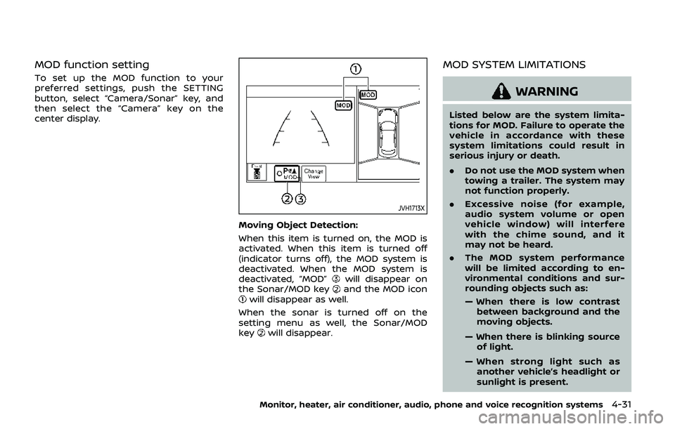
To set up the MOD function to your
preferred settings, push the SETTING
button, select “Camera/Sonar” key, and
then select the “Camera” key on the
center display.
JVH1713X
Moving Object Detection:
When this item is turned on, the MOD is
activated. When this item is turned off
(indicator turns off), the MOD system is
deactivated. When the MOD system is
deactivated, “MOD”
will disappear on
the Sonar/MOD keyand the MOD iconwill disappear as well.
When the sonar is turned off on the
setting menu as well, the Sonar/MOD
key
will disappear.
MOD SYSTEM LIMITATIONS
WARNING
Listed below are the system limita-
tions for MOD. Failure to operate the
vehicle in accordance with these
system limitations could result in
serious injury or death.
. Do not use the MOD system when
towing a trailer. The system may
not function properly.
. Excessive noise (for example,
audio system volume or open
vehicle window) will interfere
with the chime sound, and it
may not be heard.
. The MOD system performance
will be limited according to en-
vironmental conditions and sur-
rounding objects such as:
— When there is low contrast
between background and the
moving objects.
— When there is blinking source of light.
— When strong light such as another vehicle’s headlight or
sunlight is present.
Monitor, heater, air conditioner, audio, phone and voice recognition systems4-31
Page 252 of 536
4-36Monitor, heater, air conditioner, audio, phone and voice recognition systems
4. To turn off the heater and air condi-tioner system, push the “OFF” button.
A visible mist may be seen coming from
the ventilators in hot, humid conditions as
the air is cooled rapidly. This does not
indicate a malfunction.
Dehumidified defrosting or defogging:
1. Push the “
” front defroster button.
(The indicator light on the button will
illuminate.)
2. Turn the temperature control dial to set the desired temperature.
. To quickly remove ice from the out-
side of the windows, push the fan
speed increase button “
” and set it
to the maximum position.
. As soon as possible after the wind-
shield is clean, push the “AUTO” button
to return to the auto mode.
. When the “
” front defroster button
is pushed, the air conditioner will
automatically be turned on at outside
temperatures above 23°F (−5°C) to
defog the windshield, and the air
recirculate mode will automatically
be turned off.
Outside air is drawn into the passen-
ger compartment to improve the
defogging performance.
Manual operation
Fan speed control:
Push the fan speed increase “
”or
decrease “” buttons to manually con-
trol the fan speed.
Push the “AUTO” button to return to
automatic control of the fan speed.
Temperature control:
Turn the temperature control dial to set
the desired temperature.
Air flow control:
Pushing the “MODE” manual air flow
control button selects the air outlet to:
: Air flows from center and side ventila-
tors.
: Air flows from center and side ventila-tors and foot outlets.
: Air flows mainly from foot outlets.
: Air flows from defroster and foot outlets.
Air intake control:
. Push the “
” air recirculation button
to recirculate interior air inside the
vehicle. The “
” indicator light on the
button will come on. The air recircula-
tion mode cannot be activated when
the air conditioner is in the front
defrosting mode “
”. .
Push the “
” outside air circulation
button to draw outside air into the
passenger compartment. The “
”
indicator light on the button will come
on.
. To control the air intake automatically,
push and hold either the “
” air
recirculation button or the “” out-
side air circulation button (whichever
indicator light is illuminated). The
indicator lights (both air recirculation
and outside air circulation buttons)
will flash twice, and then the air intake
will switch to automatic control.
Turning the system off
Push the OFF button.
Upper vent system
When the upper vent “” button is
pushed, the air flow against the driver’s
or passenger’s upper body becomes gen-
tle. The indicator light on the button will
illuminate.
In this mode, air from the upper ventilator
flows in order to control the cabin tem-
perature without blowing air directly on
the occupants.
Push the upper vent “
” button when
you want the air conditioner to work
quickly.
To turn the system off, push the upper
Page 253 of 536
vent “” button to turn the indicator
light off.
JVH1630X
Operations on touch panel screen
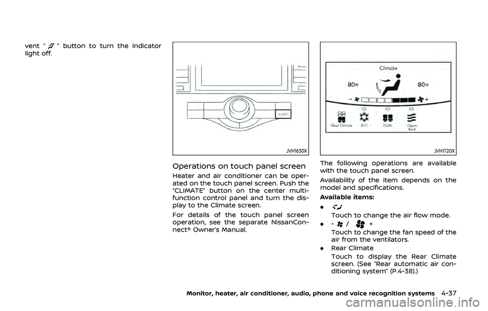
Heater and air conditioner can be oper-
ated on the touch panel screen. Push the
“CLIMATE” button on the center multi-
function control panel and turn the dis-
play to the Climate screen.
For details of the touch panel screen
operation, see the separate NissanCon-
nect® Owner’s Manual.
JVH1720X
The following operations are available
with the touch panel screen.
Availability of the item depends on the
model and specifications.
Available items:
.
Touch to change the air flow mode.
. -
/+
Touch to change the fan speed of the
air from the ventilators.
. Rear Climate
Touch to display the Rear Climate
screen. (See “Rear automatic air con-
ditioning system” (P.4-38).)
Monitor, heater, air conditioner, audio, phone and voice recognition systems4-37
Page 254 of 536
4-38Monitor, heater, air conditioner, audio, phone and voice recognition systems
.A/C
Touch to turn the air conditioner on/
off.
. DUAL
Touch to turn the DUAL mode (pas-
senger’s side temperature control)
on/off.
. Upper Vent
Touch to turn the upper vent system
on/off. (See “Upper vent system” (P.4-
36).)
JVH1621X
REAR AUTOMATIC AIR CONDITION-
ING SYSTEM
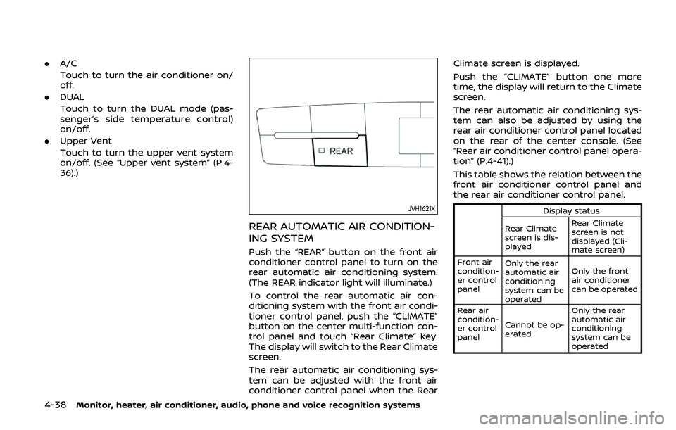
Push the “REAR” button on the front air
conditioner control panel to turn on the
rear automatic air conditioning system.
(The REAR indicator light will illuminate.)
To control the rear automatic air con-
ditioning system with the front air condi-
tioner control panel, push the “CLIMATE”
button on the center multi-function con-
trol panel and touch “Rear Climate” key.
The display will switch to the Rear Climate
screen.
The rear automatic air conditioning sys-
tem can be adjusted with the front air
conditioner control panel when the Rear Climate screen is displayed.
Push the “CLIMATE” button one more
time, the display will return to the Climate
screen.
The rear automatic air conditioning sys-
tem can also be adjusted by using the
rear air conditioner control panel located
on the rear of the center console. (See
“Rear air conditioner control panel opera-
tion” (P.4-41).)
This table shows the relation between the
front air conditioner control panel and
the rear air conditioner control panel.
Display status
Rear Climate
screen is dis-
played Rear Climate
screen is not
displayed (Cli-
mate screen)
Front air
condition-
er control
panel Only the rear
automatic air
conditioning
system can be
operated Only the front
air conditioner
can be operated
Rear air
condition-
er control
panel Cannot be op-
erated Only the rear
automatic air
conditioning
system can be
operated
Page 255 of 536
Front air conditioner control panel
operation
Automatic operation:
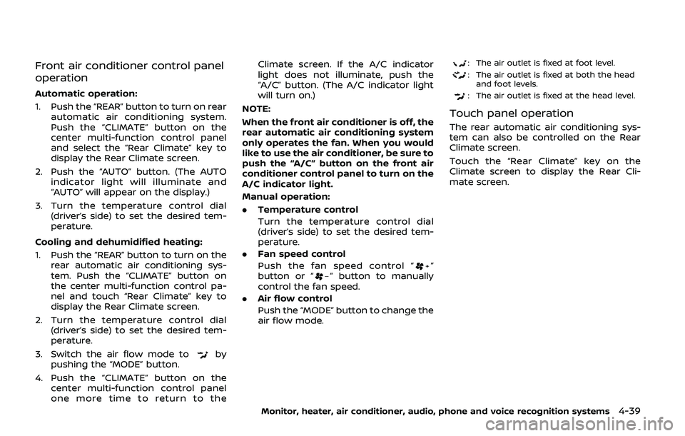
1. Push the “REAR” button to turn on rearautomatic air conditioning system.
Push the “CLIMATE” button on the
center multi-function control panel
and select the “Rear Climate” key to
display the Rear Climate screen.
2. Push the “AUTO” button. (The AUTO indicator light will illuminate and
“AUTO” will appear on the display.)
3. Turn the temperature control dial (driver’s side) to set the desired tem-
perature.
Cooling and dehumidified heating:
1. Push the “REAR” button to turn on the rear automatic air conditioning sys-
tem. Push the “CLIMATE” button on
the center multi-function control pa-
nel and touch “Rear Climate” key to
display the Rear Climate screen.
2. Turn the temperature control dial (driver’s side) to set the desired tem-
perature.
3. Switch the air flow mode to
by
pushing the “MODE” button.
4. Push the “CLIMATE” button on the center multi-function control panel
one more time to return to the Climate screen. If the A/C indicator
light does not illuminate, push the
“A/C” button. (The A/C indicator light
will turn on.)
NOTE:
When the front air conditioner is off, the
rear automatic air conditioning system
only operates the fan. When you would
like to use the air conditioner, be sure to
push the “A/C” button on the front air
conditioner control panel to turn on the
A/C indicator light.
Manual operation:
. Temperature control
Turn the temperature control dial
(driver’s side) to set the desired tem-
perature.
. Fan speed control
Push the fan speed control “
”
button or “” button to manually
control the fan speed.
. Air flow control
Push the “MODE” button to change the
air flow mode.
: The air outlet is fixed at foot level.
: The air outlet is fixed at both the head
and foot levels.
: The air outlet is fixed at the head level.
Touch panel operation
The rear automatic air conditioning sys-
tem can also be controlled on the Rear
Climate screen.
Touch the “Rear Climate” key on the
Climate screen to display the Rear Cli-
mate screen.
Monitor, heater, air conditioner, audio, phone and voice recognition systems4-39
Page 258 of 536
4-42Monitor, heater, air conditioner, audio, phone and voice recognition systems
OPERATING TIPS
When the engine coolant temperature
and outside air temperature are low, the
air flow from the foot outlets may not
operate. However, this is not a malfunc-
tion. After the coolant temperature
warms up, the air flow from the foot
outlets will operate normally.
The sensors
andlocated on the
instrument panel help maintain a con-
stant temperature. Do not put anything
on or around the sensors.
LINKING INTELLIGENT KEY (if so
equipped)
The air conditioner system settings can
be memorized for each Intelligent Key.
For more details, see “Setting memory
function” (P.3-42).
IN-CABIN MICROFILTER
The air conditioner system is equipped
with an in-cabin microfilter which collects
dirt, pollen, dust, etc.
To make sure the air conditioner heats,
defogs, and ventilates efficiently, replace
the filter in accordance with the specified
maintenance intervals listed in the “9.
Maintenance and schedules” section. It is
recommended to see a NISSAN dealer to
replace the filter.
The filter should be replaced if the air flow decreases significantly or if win-
dows fog up easily when operating the
heater or air conditioner.
SERVICING AIR CONDITIONER
The air conditioner system in your NISSAN
is charged with a refrigerant designed
with the environment in mind.
This re-
frigerant will not harm the earth’s
ozone layer. However, special charging
equipment and lubricant are required
when servicing your NISSAN air condi-
tioner. Using improper refrigerants or
lubricants will cause severe damage to
your air conditioner system. (See “Capa-
cities and recommended fluids/lubri-
cants” (P.10-2) for air conditioner system
refrigerant and lubricant recommenda-
tions.)
Your NISSAN dealer will be able to service
your environmentally friendly air condi-
tioner system.
WARNING
The system contains refrigerant un-
der high pressure. To avoid personal
injury, any air conditioner service
should be done only by an experi-
enced technician with the proper
equipment.
WINDOW ANTENNA
The antenna pattern is printed inside the
rear side glass.
CAUTION
. Do not place metalized film near
the 3rd row seat window or at-
tach any metal parts to it. This
may cause poor reception or
noise.
. When cleaning the inside of the
rear side window, be careful not
to scratch or damage the rear
side window antenna. Lightly
wipe along the antenna with a
dampened soft cloth.
ANTENNA
Page 262 of 536

Intelligent Blind Spot Intervention (I-BSI) (if
so equipped) ........................................................................\
.......... 5-43I-BSI system operation ................................................... 5-45
Turning the I-BSI system ON/OFF ......................... 5-47
How to enable/disable the I-BSI system ......... 5-48
I-BSI system limitations ................................................. 5-48
I-BSI driving situations .................................................... 5-50
System temporarily unavailable ............................. 5-55
System malfunction .......................................................... 5-56
System maintenance ....................................................... 5-56
Intelligent Back-up Intervention (I-BI) (if
so equipped) ........................................................................\
.......... 5-57
I-BI system operation ...................................................... 5-59
How to enable/disable the I-BI system ............ 5-63
I-BI system precautions ................................................. 5-64
System temporarily unavailable ............................. 5-65
System malfunction .......................................................... 5-66
System maintenance ....................................................... 5-66
Intelligent Cruise Control (ICC) ....................................... 5-67 How to select the cruise control mode ............ 5-69
Vehicle-to-vehicle distance control mode ...... 5-69
Conventional (fixed speed) cruise
control mode ........................................................................\
.. 5-85
Intelligent Distance Control (I-DC) (if
so equipped) ........................................................................\
.......... 5-89 I-DC system operation .................................................. 5-91
Turning the I-DC system ON/OFF ......................... 5-94
How to enable/disable the I-DC system .......... 5-95
I-DC system display and indicators ..................... 5-95 I-DC system limitations ............................................... 5-96
System temporarily unavailable ........................... 5-99
System malfunction ................................................... 5-101
System maintenance ................................................ 5-101
Automatic Emergency Braking (AEB) ................... 5-102 AEB system operation .............................................. 5-104
Turning the AEB system ON/OFF ................... 5-106
AEB system limitations ............................................ 5-107
System temporarily unavailable ....................... 5-108
System malfunction ................................................... 5-109
System maintenance ................................................ 5-110
Intelligent Forward Collision
Warning (I-FCW) ...................................................................... 5-111 I-FCW system operation ......................................... 5-113
Turning the I-FCW system ON/OFF ............... 5-114
I-FCW system limitations ........................................ 5-116
System temporarily unavailable ....................... 5-118
System malfunction ................................................... 5-118
System maintenance ................................................ 5-119
Break-in schedule ................................................................. 5-120
Fuel efficient driving tips ................................................ 5-120
Increasing fuel economy ................................................ 5-121
NISSAN all-mode 4WD® (if so equipped) ............ 5-121 NISSAN all-mode 4WD® system ........................ 5-122
4WD shift switch ........................................................... 5-126
4WD shift indicator ..................................................... 5-127
4WD warning light ....................................................... 5-127
Hill Start Assist system ..................................................... 5-129
Parking/parking on hills .................................................. 5-130