2019 MERCEDES-BENZ SPRINTER battery
[x] Cancel search: batteryPage 244 of 354

&
WARNING Risk ofexplosion from hydro‐
ge nga s igniting
A battery generates hydrogen gas during the
ch arging process. If there is a short circuit or
spar ksstart toform ,th ere is a danger of the
hy drogen gas igniting. #
Make sure that the positive term inal of
th e connected battery does not come
into contact with vehicle parts. #
Never place me tal objects or tools on a
batter y. #
When connecting and disconnecting the
batter y,yo u must obse rveth e described
order forth e battery clamps. #
When giving starting assistance, alw ays
make sure that you on lyconnect battery
te rm inals with identical polarity. #
During starting assis tance, you must
obse rveth e described order for con‐
necting and disconnecting the jumper
cables. #
Do not connect or disconnect the bat‐
te ry cla mp s while the engine is running. &
WARNING Risk ofexplosion during
ch arging process and starting assis tance
During thech arging process and starting
assis tance, the battery may release an explo‐
sive gas mixture. #
Avoid fire , open flames, creating spar ks
and smoking. #
Make sure that there is suf ficient venti‐
lation du ring thech arging process and
during starting assis tance. #
Do not lean over a batter y. &
WARNING Risk ofexplosion from a fro‐
zen battery
A dischar ged battery may freeze at temp era‐
tures slightly abo veor below freezing point.
During starting assis tance or battery charg‐
ing, battery gas may be released. #
Alwaysth aw a frozen battery out first
before charging it or per form ing starting
assis tance. If
th ewa rning/indicator lamps do not light up in
th e instrument display around or below freezing point, it is
very likely that the discharged battery
has frozen.
In this case, obser vethefo llowing points:
R do not give theve hicle starting assis tance or
ch arge the battery
R the service life of a battery that has been
th awe d may be reduced drastically
R thest art-up behavior may de teriorate, partic‐
ularly at low temp eratures
R it is recommended that you ha veath awed
battery checked at a qualified specialist work‐
shop
* NO
TEDama gecaused bynume rous or
ex tended attempts tostart the engine Nume
rous or extended attempts tostart the
engine may damage the catalytic con verter
due tonon-combu sted fuel. #
Avoid numerous and extended attem pts
to start the engine. Obser
vethefo llowing points during starting
assis tance and when charging the battery:
R only use undamaged jumper cables/charging
cables with a suf ficient cross-section and
insula tedte rm inal clamps
R non-insulated parts of thete rm inal clamps
must not come into con tact wi thother me tal
parts while the jumper cables/charging
cables are connected tothe battery/jump-
st art connection point
R the jumper cables/charging cable must not
come into contact with any parts which may
mo vewhen the engine is running
R alwa ys make sure that nei ther you nor the
battery is electros tatically charged
R alwayske ep away from fire and open flames
R do not lean over a battery
R when charging: only use a battery charger
th at has been tested and appr ovedby
Mercedes-Benz and read the operating
instructions foryo ur charge r before charging
th e batter y.
Obser vethe additional following points during
st arting assis tance:
R starting assis tance may only be pr ovided
using batteries with a nominal voltage of 12 V
R theve hicles must not touch each other 220
Breakdown assis tance
Page 245 of 354

R
vehicles with a gasoline engine: only per‐
fo rm starting assis tance when the engine and
ex haust sy stem are cold #
Vehicles with a battery main switch: check
whe ther the battery main switch is switched
on (/ page114). #
Secu retheve hicle using the parking brake. #
Vehicles with automatic transmission:
shift the transmission toposition 005D. #
Switch off the ignition and all electrical con‐
sumers. #
Open the hood (/ page 202). Example: jump-s
tart connection point
% Right-hand-drive
vehicles: the jump-s tart
connection points may be on the opposite
side. #
Remo vethe co ver from the positive term inal
on the donor batter y. #
First, connect the positive term inal clamp of
th e jumper cables/charging cables tothe
positive term inal of theot her vehicle's bat‐
te ry. #
With positive term inal clamp 2ofthe
jumper cable, slide there d pr otective cap on
jump-s tart connection point 1back with a
clockwise turn. #
Connect the positive term inal clamp tothe
positive term inal of jump-s tart connection
point 1. #
During starting assistance: start the engine
of the donor vehicle and let it run at idle
speed. #
Connect the negative term inal of the donor
battery tothe ground point of your ow nve hi‐ cle with
the jumper cable/charging cable.
Begin with the donor batter y. #
During starting assistance: start the engine
on your ow nve hicle. #
When charging: start thech arging process. #
During starting assistance: letthe engine
ru nfo r a few minutes. #
During starting assistance: before discon‐
necting the jumper cable, switch on an elec‐
trical consumer on your ow nve hicle, e.g. the
re ar wind owheater or lighting.
When thest arting assis tance/charging process is
comple te: #
First,re mo vethe jumper cables/charging
cables from the ground point and negative
te rm inal of theot her vehicle's batter y,then
from the positive term inal of jump-s tart con‐
nection point 1and the positive term inal of
th eot her vehicle's batter y.Each time, begin
at the contacts on your ow nve hicle.
The red pr otective cap springs back toits ini‐
tial position when positive term inal clamp 2
is disconnected from jump-s tart connection
point 1.
Fu rther information can be obtained at a qualified
specialist workshop. Installing/removing
thefloor co vering (vehi‐
cles with rear wheel drive) &
WARNING Risk of accident due to
objects in the driver's foot we ll
Objects in the driver's foot we ll may impede
pedal tr avel or block a depressed pedal.
This jeopardizes the operating and road
saf ety of theve hicle. #
Stow all objects in theve hicle securely
so that they cannot getinto the driver's
fo ot we ll. #
Ensure floor mats and carpets cannot
slip and pr ovide suf ficient room forthe
pedals. #
Do not lay multiple floor mats or carpets
on top of one ano ther. Breakdown assis
tance 221
Page 246 of 354
#
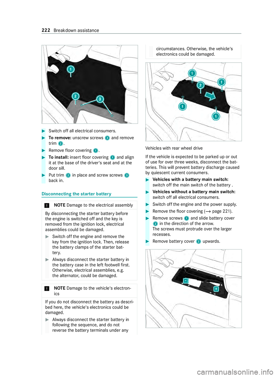
Switch off all electrical consumers. #
Toremo ve:unscr ewscrews3 and remo ve
trim 2. #
Remo vefloor co vering 1. #
Toinstall: insertfloor co vering 1 and align
it at the base of the driver's seat and at the
door sill. #
Put trim 2in place and scr ewscrews3
back in. Disconnecting
thest ar ter battery *
NO
TEDama getothe electrical assembly By disconnecting
thest ar ter battery before
th e engine is switched off and theke y is
re mo ved from the ignition loc k,electrical
assemblies could be damaged. #
Switch off the engine and remo vethe
ke y from the ignition loc k.Then, release
th e battery clamps of thest ar ter bat‐
te ry. #
Always disconnect thest ar ter battery in
th e battery case in the left foot we llfirs t.
Otherwise, electrical assemblies, e.g.
th e alternator, could be damaged. *
NO
TEDama getotheve hicle's electron‐
ics If
yo u do not disconnect the battery as descri‐
bed here, theve hicle's electronics could be
damaged. #
Always disconnect thest ar ter battery in
fo llowing the sequence, and do not
re ve rseth e battery term inals under any circums
tances. Otherwise, theve hicle's
electronics could be damaged. Ve
hicles with rear wheel drive
If th eve hicle is expected tobe par ked up or out
of use forove rth re ewe eks, disconnect the bat‐
te ries. This will pr event battery discharge caused
by quiescent cur rent consumers. #
Vehicles with a battery main switch:
switch off the main switch of the battery . #
Vehicles without a battery main switch:
switch off all electrical consumers. #
Switch off the engine and the po wer supp ly. #
Remo vethefloor co vering (/ page 221). #
Remo vescr ews1 and slide battery co ver
2 inthe direction of the ar row.
The scr ews must pr otru de ove rth e lar ger
re cesses. #
Remo vebattery co ver2 upwards. 222
Breakdown assi stance
Page 247 of 354

#
Firstloosen and remo vethe negative term inal
clamp on the battery so that the clamp is no
longer in contact with thete rm inal. #
Remo vethe positive term inal clamp co ver. #
Loosen the positive term inal clamp and fold it
up tothe side, toge ther with the prefuse box. Re
moving/installing the star ter battery Ve
hicles with rear wheel drive: removing the
st ar ter battery #
Disconnect thest ar ter battery (/ page 222). #
Remo vebreather hose 1with the connector
brac ket from the connection on the degassing
co ver. #
Pull out and remo vescr ews2 of brac ket3
up wa rds. #
Slide thest ar ter battery from its anchorage in
th e direction of tr avel. #
Foldthe bars of thest ar ter battery upwards
and remo vethest ar ter battery from the bat‐
te ry box.
Ve hicles with rear wheel drive: installing the
st ar ter battery #
When reconnecting thest ar ter batter y,
obser vethe saf ety measures and pr otection
no tes (/ page219). #
Inse rtthest ar ter battery into the battery box. #
Fold down the bars of thest ar ter batter y. #
Slide thest ar ter battery into its anchorage in
th e opposite direction tothe direction of
tra vel. #
Insert brac ket3. #
Tighten scr ews2 on brac ket3 which holds
th e battery in place. #
Attach breather hose 1with the connector
brac ketto the connection of theve ntilation
co ver. #
Reconnect thest ar ter battery (/ page 222).
Mercedes-Benz recommends that you ha vethe
st ar ter battery replaced at a qualified specialist
wo rkshop, e.g. an authorized Mercedes-Benz
Center.
If yo uwa nttoreplace thest ar ter battery yourself,
obse rveth efo llowing no tes:
R Alwaysre place a defective star ter battery
with a star ter battery which meets the spe‐
cific requirements of theve hicle.
R Carryover de tach able parts such as theve nt
hose, elbow fitting or term inal co ver from the
st ar ter battery tobe replaced.
R Make sure that theve nt hose is al ways con‐
nected toits original opening on the battery
side.
Ins tallth eex isting or newly supplied stop
plugs. Breakdown assis
tance 223
Page 248 of 354
Otherwise,
gases or battery acid could
escape.
R Make sure that the de tach able parts are con‐
nec ted in the same way as before. Disconnecting
the auxiliary bat tery inthe
engine compa rtment *
NO
TEDama getothe electrical assembly By disconnecting
thest ar ter battery before
th e engine is switched off and theke y is
re mo ved from the ignition loc k,electrical
assemblies could be damaged. #
Switch off the engine and remo vethe
ke y from the ignition loc k.Then, release
th e battery clamps of thest ar ter bat‐
te ry. #
Always disconnect thest ar ter battery in
th e battery case in the left foot we llfirs t.
Otherwise, electrical assemblies, e.g.
th e alternator, could be damaged. *
NO
TEDama getotheve hicle's electron‐
ics Incor
rectly disconnecting the auxiliary battery
can cause damage totheve hicle's electron‐
ics. #
Always disconnect the auxiliary battery
as described in thefo llowing sequence.
Do not reve rseth e battery term inals
under any circums tances. #
Obser vethe saf ety measures and pr otection
notices when disconnecting the auxiliary bat‐
te ry ( / page 219). #
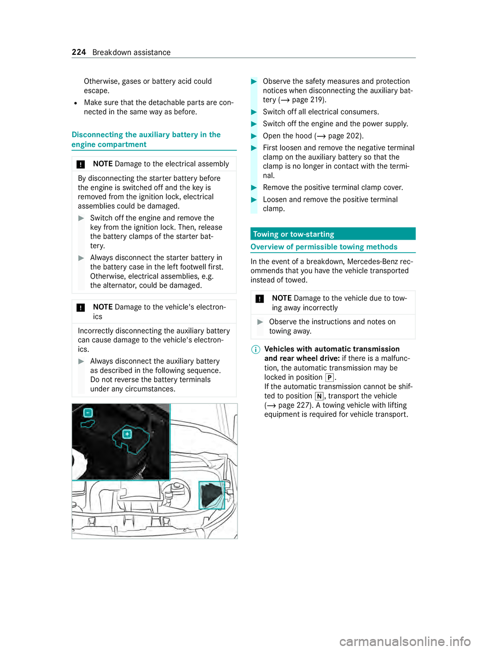
Swit choff all electrical consumers. #
Switch off the engine and the po wer supp ly. #
Open the hood (/ page 202). #
Firstloosen and remo vethe negative term inal
clamp on the auxiliary battery so that the
cla mp is no longer in con tact wi th thete rm i‐
nal. #
Remo vethe positive term inal clamp co ver. #
Loosen and remo vethe positive term inal
clamp. To
wing or tow- starting Overview of permissible
towing me thods In
theeve nt of a breakdown, Mercedes-Benz rec‐
ommends that you ha vetheve hicle transpor ted
ins tead of towe d.
* NO
TEDama getotheve hicle due to tow‐
ing away incor rectly #
Obser vethe instructions and no tes on
to wing away. %
Ve
hicles with automatic transmission
and rear wheel drive: ifth ere is a malfunc‐
tion, the automatic transmission may be
loc ked in position 005D.
If th e automatic transmission cann otbe shif‐
te dto position 005C, transport theve hicle
(/ page 227). A towing vehicle with lifting
equipment is requ ired forve hicle transport. 224
Breakdown assis tance
Page 249 of 354
Pe
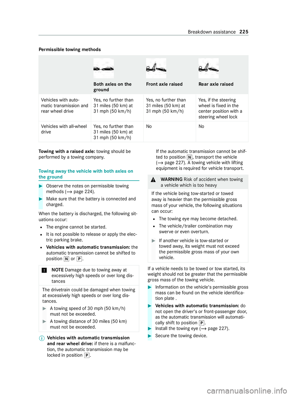
rm issible towing me thods Bo
th axles on the
gr ound Fr
ont axle raised Re
ar axle raised
Ve hicles with auto‐
matic transmission and
re ar wheel drive Ye
s, no fur ther than
31 miles (50 km) at
31 mp h (50 km/h) Ye
s, no fur ther than
31 miles (50 km) at
31 mp h (50 km/h) Ye
s, if thesteering
wheel is fixe d in the
center position wi th a
st eering wheel lock
Ve hicles with all-wheel
drive Ye
s, no fur ther than
31 miles (50 km) at
31 mp h (50 km/h) No
NoTo
wing with a raised axle: towing should be
per form ed byato wing compan y. To
wing away theve hicle with bo thaxles on
th egr ound #
Obser vethe no tes on permissible towing
me thods (/ page 224). #
Make sure that the battery is connected and
ch arge d.
When the battery is dischar ged, thefo llowing sit‐
uations occur:
R The engine cannot be star ted.
R It is not possible torelease or apply the elec‐
tric parking brake.
R Vehicles with automatic transmission: the
automatic transmission cannot be shif tedto
position 005Cor005D.
* NO
TEDama gedue to to wing away at
exc essively high speeds or over long dis‐
ta nces The driv
etra in could be damaged when towing
at exc essively high speeds or over long dis‐
ta nces. #
Atowing speed of 30 mph (50 km/h)
must not be exceeded. #
Atowing distance of 30 miles (50 km)
must not be exceeded. %
Ve
hicles with automatic transmission
and rear wheel drive: ifth ere is a malfunc‐
tion, the automatic transmission may be
loc ked in position 005D. If
th e automatic transmission cann otbe shif‐
te dto position 005C, transport theve hicle
(/ page 227). A towing vehicle with lifting
equipment is requ ired forve hicle transport. &
WARNING Risk of accident when towing
a ve hicle which is too heavy
If th eve hicle being tow- star ted or towed
aw ay is heavier than the permissible gross
mass of your vehicle, thefo llowing situations
can occur:
R The towing eye may become de tach ed.
R The vehicle/trailer combination may
swer veoreve nove rturn. #
If ano ther vehicle is tow- star ted or
to we daw ay, its weight must not exceed
th e permissible gross mass of your own
ve hicle. If a
vehicle needs tobe towe d or tow star ted, its
we ight should not be greaterth at the permissible
gross mass of theto wing vehicle. #
Information on theve hicle's permissible gross
mass can be found on theve hicle identifica‐
tion plate . #
Vehicles with automatic transmission: do
not open the driver's or front-passen ger door,
as the automatic transmission will automati‐
cally shift toposition 005D. #
Installth eto wing eye (/ page 227). #
Secure theto wing device. Breakdown assis
tance 225
Page 311 of 354

Display messages
Possible causes/consequences and 0050 0050Solutions
Engine Oil Level Low
Stop Vehicle Turn
Engine Off *
NO
TEEngine damage caused bydriving with insuf ficient
engine oil #
Avoid long journe yswith insuf ficient engine oil. #
Stop in a safe location immediately. Do not continue driving. #
Switch off the engine. #
Check the engine oil le vel.
Ad d engine oil (/ page 205).
Obser vethe no tes on engine oil (/ page 267).
00B2
Check Engine Oil At
Next Refueling *T
he engine oil le vel has fallen tothe minimum le vel.
* NO
TEEngine damage caused bydriving with insuf ficient
engine oil #
Avoid long journe yswith insuf ficient engine oil. #
Che ckthe engine oil le vel at the next fuel stop.
To p up engine oil (/ page 205).
Obser vethe no tes on engine oil (/ page 267).
003D
Stop Vehicle Leave
Engine Running *T
he battery's charge leve l is too lo w. #
Stop in a safe location immediately. Do not continue driving! #
Let the engine run. #
Do not continue driving until the display message goes out.
003D
Stop Vehicle See Opera-
tor's Manual *T
he battery is no longer being charge d and has reached an exces‐
sively low battery charge leve l.
* NO
TEPossible engine damage if you continue driving #
Do not continue driving under any circum stances. #
Consult a qualified specialist workshop. #
Stop in a safe location immediately. Do not continue driving. #
Switch off the engine. #
Consult a qualified specialist workshop.
003D
12 V Battery See Opera-
tor's Manual *T
he engine is off and the battery charge leve l is too lo w. #
Switch off electrical consumers that are not required. #
Let the engine runfo r a few minutes or drive an extended dis‐
ta nce.
The battery is charge d.
003D
See Operator's Manual *T
he battery is no longer being charge d.
* NO
TEPossible engine damage if you continue driving #
Do not continue driving under any circum stances. #
Consult a qualified specialist workshop. Display messages and
warning and indicator lamps 287
Page 316 of 354

Display messages
Possible causes/consequences and 0050 0050Solutions
Key Not Detected (red
display message) R
You cannot lock theve hicle centra lly. #
Ensure that theke y is in theve hicle.
If th eke y de tection function has a malfunction due toastro ngradio
signal source, proceed as follo ws: #
Stop theve hicle immediately, paying attention toroad and traf‐
fi c conditions. #
Place theke y in the slot forst arting with theke y (/ page104).
00AF Key No t Detected (white
display message) *T
hekey is cur rently not de tected. #
Change theke y's position in theve hicle. #
Ifth eke y is still not de tected, start the engine with theke y in
th e slot(/ page104).
00AF
Replace Key Ba ttery*T
hekey's bat tery isflat. #
Change the battery (/ page 42).
00AF
Obtain a New Key *T
hekey must be replaced. #
Visit a qualified specialist workshop. Ve
hicle Display messages
Possible causes/consequences and 0050 0050Solutions
00B2
Check Washer Fluid *W
asher fluid le vel in washer reser voir has fallen below the minimum. #
Top up washer fluid (/ page 208). *A
t least one door is open. #
Close all the doors. *T
he hood is open. &
WARNING Risk of accident if the engine hood is unlatched
while driving
An unloc ked engine hood may open up when theve hicle is in
motion and block your vie w. #
Never unlatch the engine hood while driving. #
Before every trip, ensure that the engine hood is latched. #
Stop in a safe location immediately. #
Close the hood. 292
Display messages and warning and indicator lamps