2019 MERCEDES-BENZ SL ROADSTER tow
[x] Cancel search: towPage 291 of 330

The
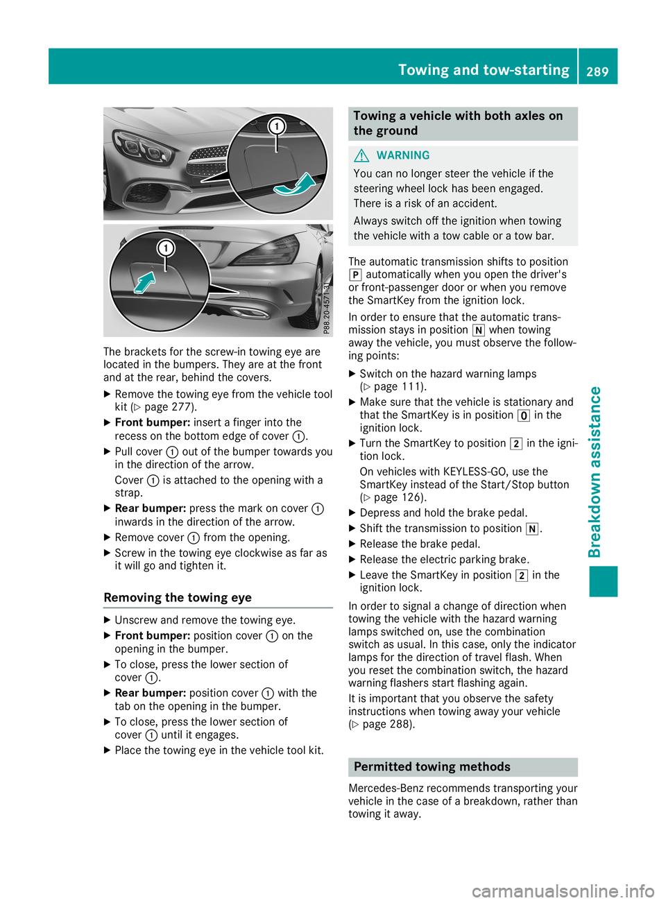
bracket sfor the screw-in towingeyeare
located inthe bumpers. Theyareatthe front
and atthe rear, behind thecovers.
X Remove thetowing eyefrom thevehicle tool
kit (Ypage 277).
X Front bumper:insert afinger intothe
recess onthe botto medge ofcover 0043.
X Pull cover 0043out ofthe bumper towards you
in the direction ofthe arrow.
Cover 0043isattached tothe opening witha
strap.
X Rear bump er:press themark oncover 0043
inwards inthe direction ofthe arrow.
X Remove cover0043from theopening.
X Scr ew inthe towing eyeclock wiseasfar as
it will goand tighten it.
Removing thetowing eye X
Unsc rewand remove thetowing eye.
X Front bumper:position cover0043onthe
opening inthe bumper.
X To close, pressthelower section of
cover 0043.
X Rear bump er:position cover0043with the
tab onthe opening inthe bumper.
X To close, pressthelower section of
cover 0043until itengages.
X Place thetowing eyeinthe vehicle toolkit. Towing
avehicle withboth axles on
the ground G
WARNIN
G
You cannolonger steerthevehicle ifthe
steerin gwheel lockhasbeen engaged.
There isarisk ofan accident .
Always switchoffthe ignition whentowing
the vehicle withatow cable oratow bar.
The automatic transmission shiftstoposition
005D automatically whenyouopen thedriver's
or front -passenger doororwhen youremove
the Smart Keyfrom theignition lock.
In order toensure thattheautomatic trans-
mission staysinposition 005Cwhen towing
away thevehicle, youmust observe thefollow-
ing points:
X Switch onthe hazard warning lamps
(Y page 111).
X Make surethatthevehicle isstation aryand
that theSmart Keyisin position 0092inthe
ignition lock.
X Turn theSmart Keytoposition 0048inthe igni-
tion lock.
On vehicles withKEYLE SS-GO, usethe
Smart Keyinstead ofthe Start /Stopbutton
(Y page 126).
X Depress andhold thebrake pedal.
X Shift thetrans mission toposition 005C.
X Release thebrake pedal.
X Release theelectric parking brake.
X Leave theSmart Keyinposition 0048inthe
ignition lock.
In order tosignal achange ofdirection when
towing thevehicle withthehazard warning
lamps switched on,use thecombinat ion
switch asusual. Inthis case, onlytheindicator
lamps forthe direction oftravel flash.When
you reset thecombinat ionswitch, thehazard
warning flashersstartflashing again.
It is important thatyouobserve thesafety
instr uctions whentowing awayyourvehicle
(Y page 288). Permit
tedtowing methods
Mercedes- Benzrecomm endstransportin gyour
vehicle inthe case ofabreakdown, ratherthan
towing itaway . Towing
andtow-sta rting
289Breakdown assistance Z
Page 292 of 330

When
towing away,useatowing ropeora
towing barwith both axles onthe ground. Do
not use anytow barsystems. Towing
thevehicle withtherear axle
raised
! The
ignition mustbeswitched offifyou
are towing thevehicle withtherear axle
raised. Interven tionbyESP®
could other-
wise damage thebrake system.
! Vehicles
withautomatic transmission must
not betowed withtherear axle raised. The
vehicle/t railercombin ationmayotherwise
swerve oreven rollover. Tr
anspor tingthevehicle
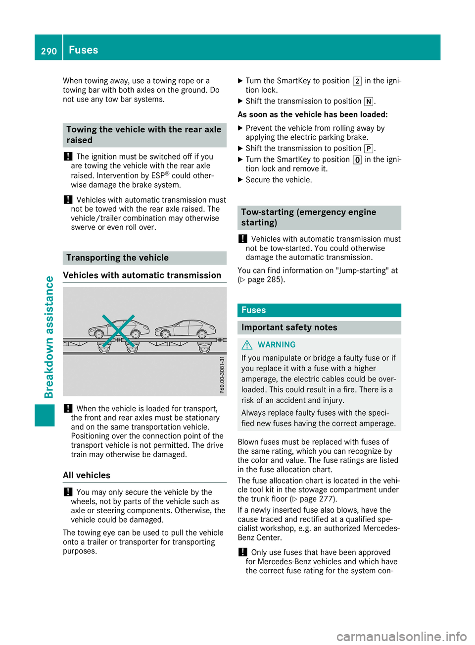
Vehicles withautomat ictransmission !
When
thevehicle isloaded fortran sport,
the fron tand rear axles mustbestation ary
and onthe same transportat ionvehicle.
Position ingover theconn ection pointofthe
tran sport vehicle isnot permitt ed.The drive
train mayotherwise bedamaged.
All vehicles !
You
may onlysecure thevehicle bythe
wheels, notbyparts ofthe vehicle suchas
axle orsteerin gcompon ents.Other wise, the
vehicle couldbedamaged.
The towing eyecan beused topull thevehicle
ont oatrailer ortran sporter fortran sportin g
purposes. X
Turn theSmart Keytoposition 0048inthe igni-
tion lock.
X Shift thetran smission toposition 005C.
As soon asthe vehicle hasbeen loaded:
X Preven tthe vehicle fromrolling awayby
applying theelectr icparking brake.
X Shift thetran smission toposition 005D.
X Turn theSmart Keytoposition 0092inthe igni-
tion lock andremove it.
X Secure thevehicle. Tow-sta
rting (emergency engine
star ting)
! Vehicles
withautomatic transmission must
not betow-s tarted. You could otherwise
damage theautomatic transmission.
You canfind inform ationon"Jump-start ing"at
(Y page 285). Fuses
Impor
tantsafety notes G
WARNIN
G
If you manipulate orbridge afaulty fuseorif
you replace itwith afuse withahigher
amperage, theelectr iccables couldbeover-
loaded. Thiscould result inafire. There isa
risk ofan accident andinjury.
Always replace faultyfuseswiththespeci-
fied new fuses having thecorr ectamperage.
Blown fusesmustbereplaced withfuses of
the same rating,which youcan recogn izeby
the color andvalue. Thefuse rating sare listed
in the fuse allocation chart.
The fuse allocation chartislocated inthe vehi-
cle tool kitinthe stowage compartmentunder
the trun kfloor (Ypage 277).
If anewly insertedfuse alsoblows, havethe
cause tracedand rectified ataqualified spe-
cialist workshop, e.g.anauthorized Mercedes-
Benz Center .
! Only
usefuses thathave been approved
for Mercedes- Benzvehicles andwhich have
the corr ectfuse rating forthe system con- 290
FusesBr
eakdown assistance
Page 294 of 330

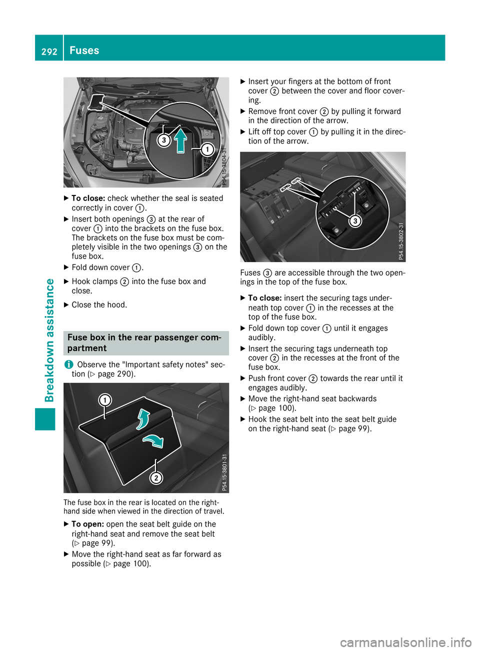
X
To clos e:che ckwhethe rthe sealis sea ted
corr ectlyin cove r0043.
X Inse rtbo th openi ngs 0087atthe rearof
cove r0043 into thebrackets onthe fusebo x.
The brackets onthe fusebo xmu stbe com-
pl etel yvis ible in the two openi ngs 0087onthe
fus ebo x.
X Fol ddo wn cove r0043.
X Hoo kcla mps 0044into thefusebo xand
clo se.
X Close thehood. Fus
ebo xin the rear pass engerco m-
partmen t
i Obs
ervethe "Impo rtant safety notes "sec-
tio n(Y page 290 ). The
fusebox inthe rearis locate don the right-
ha nd side when viewe din the directi onoftrav el.
X To ope n:open the seatbe ltgu ide on the
rig ht-ha ndsea tand remove theseatbe lt
(Y page 99).
X Mov ethe right-ha ndsea tas far forw ardas
po ssi ble (Y page 100 ). X
Inse rtyo ur fing ers atthe bottom offront
cove r0044 betwe enthe cove rand floor cove r-
ing .
X Re move frontcover0044 bypulling itforw ard
in the directi onofthe arrow .
X Lif toff top cove r0043 bypulling itin the direc-
tio nof the arrow . Fus
es0087 are acce ssible thro ughthe two open-
ing sin the top ofthe fusebo x.
X To clos e:ins ert the secu ringtagsund er-
nea thtop cove r0043 inthe rece ssesat the
top ofthe fusebo x.
X Fol ddo wn top cove r0043 unti lit enga ges
au dibly.
X Inse rtthe secu ringtagsund erne athtop
cove r0044 inthe rece ssesat the front ofthe
fus ebo x.
X Pu sh front cover0044 tow ardsthe rearunti lit
enga gesaudibly.
X Mov ethe right-ha ndsea tba ckwa rds
(Y page 100 ).
X Hoo kthe seatbe ltinto theseatbe ltgu ide
on the right-ha ndsea t(Y page 99). 29
2 Fu
sesBreakdo wnassis tan ce
Page 302 of 330

Imp
ortant safety notes G
WAR
NING
Eac htire, includin gth espar e(if pro vide d),
sho uld bechecke dat least once amon th
when cold and inflat ed tothepre ssur erec -
omm ended bytheveh icleman ufactureron
th eTir eand Load ingInfor mat ionplac ardon
th edriv er'sdoor B-pillar orthetire pre ssur e
label ontheins ide ofthefuel filler flap .If
your vehiclehas tires ofadif fer entsiz eth an
th esiz eind icat edon theTir eand Load ing
In for mat ionplac ardorthetire pre ssur e
label, youshould determ inethepro per tire
pre ssur efor those tires .
As anadded safetyfeat ure, your vehiclehas
been equipp edwithatire pre ssur emon itor-
ing syst em(TPM S)that illum inatesa low tire
pre ssur ete lltale when oneor mor eof your
ti res are sign ificant lyund erinflat ed. Accord-
ing ly,when thelow tire pre ssur ete lltale illu-
min ates,you should stop and checkyour
ti res assoo nas pos sible ,and inflat eth em to
th epro per pressur e.Drivin gon asign ifi-
can tly und erin flatedtire caus esthetire to
ove rheatand canlead totire failur e.Un der -
inf lat ion also reduce sfuel efficien cy and tire
tr ead life,and may affectth eveh icle's han -
dlin gand stoppi ngabilit y.
Pleas eno te that theTPM Sis no ta subs ti-
tut efor proper tire main tenan ce,and itis
th edriv er'sres pon sibil ity to main tainco r-
rec ttire pre ssur e,eve nif und erinflat ion has
no treac hedthelev elto trigge rillum ination
of theTPM Slow tire pre ssur ete lltale.
US Aon ly:
Your vehiclehas also been equipp edwitha
TPM Smalf unction indicat ortoind icat eif th e
syst emisno toper ating pro perly.The TPM S
malf unction indicat orisco mbin edwithth e
low tire pre ssur ete lltale. When thesyst em
det ects amalf unction ,th ewarn inglamp will
flas hfor appr oximat elyamin ute and then
rem aincontinuo usly illum inated. This
seque ncewill berep eatedeve rytime the
veh icleis start ed aslon gas themalf unction
ex ist s. When
themalf unction indicat orisillum ina-
te d, thesyst emmay notbe able todet ector
sign allow tire pre ssur eas intended. TPMS
malf unction smay occur foravar ietyof rea-
son s,inc ludin gth emoun ting ofinc omp ati-
ble replace men tor altern ate tires orwhee ls
on theveh icleth at pre ven tth eTPM Sfrom
fun ction ing properly.Alw ays checkth e
TPM Smalf unction telltale afterrep laci ng
on eor mor etires orwhee lson your vehicle
to ensur eth at therep lace men tor altern ate
ti res and whee lsallow theTPM Sto continue
to fun ction properly.
It is thedriv er'sres pon sibil ity to set thetire
pre ssur eto that rec omm ended forcold tires
whic his suit able fortheoper ating situati on
(Y page 296). Not eth at theco rrec ttire pre s-
sur efor thecur ren toper ating situati onmust
fir st be taug ht-in tothetire pre ssur emon itor.
If asubs tantial loss ofpre ssur eoc cur s,the
warn ingthres hold forthewarn ingmes sage is
align edtothetaug ht-in refere ncevalue s.
Rest artthetire pre ssur emon itor afteradj ust -
ing thepre ssur eof theco ld tires
(Y page 301). The curren tpre ssur esare
sav edasnewref ere ncevalue s.As ares ult,a
warn ingmes sage willappear ifth etire pre s-
sur edro pssign ificant ly.
The tire pre ssur emon itor does notwarn youof
an incorrectly set tire pre ssur e.Obs erveth e
no teson therec omm ended tire pre ssur e
(Y page 296).
The tire pre ssur emon itor isno table towarn
you ofasudde nloss ofpre ssur e,e.g. ifth e
ti re ispen etrat ed byafor eign object.In the
eve ntofasudde nloss ofpre ssur e,brin gth e
veh icleto ahalt bybrak ingcareful ly.Avoid
abrup tst eer ing mov eme nts.
The tire pre ssur emon itor has ayellow warning
lamp intheins trumen tclus terfor indicat ing
pre ssur eloss oramalf unction .Whet herthe
warn inglamp flashes orligh tsup indicat es
whet heratire pre ssur eis toolow orthetire
pre ssur emon itor ismalf unction ing :
R ifth ewarn inglamp islit continuo usly, the
ti re pre ssur eon oneor mor etires issign ifi-
can tly to olow. Thetire pre ssur emon itor is
no tmalf unction ing .
R ifth ewarn inglamp flashes forappr ox-
imat elyamin ute and then rem ainslit con- 300
Ti
re pressu reWheels andtire s
Page 319 of 330

G
WARNING
If you tighten thewhee lbolts orwhee lnuts
when thevehicl eis rais ed, the jack couldtip
over. There isarisk ofinjury .
Only tighten thewhee lbolts orwhee lnuts
when thevehicl eis on the grou nd.
Alwa yspay attention tothe instructions and
safety notesinthe "Changi ngawhee l"section
(Y pag e313).
Only usewhee lbolts thathave been designed
for the whee land thevehicl e.For safety rea-
sons, Mercede s-Benzrecommends thatyou
only usewhee lbolts whichhave been
app roved forMercede s-Benzvehiclesand the
respe ctivewheel.
! Merce
des-AMGvehi cles:duri ngremova l
and repos itioning ofthe whee l,the whee l
rim can strike thecerami c-brake discand
dama geit.There fore,youshou ldproceed
carefu llyand getasecond personassi stto
you .Alternativel y,you can useasecond
ali gnment bolt.
! To
prevent damagetothe paintwork, hold
the whee lsecure lyaga inst thewhee lhub
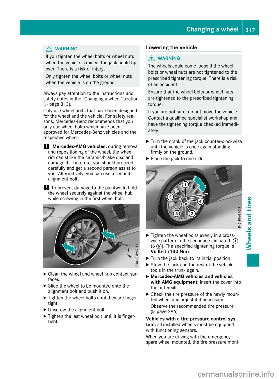
whi lescrewi nginthe first whee lbolt. X
Cle anthe whee land whee lhub contact sur-
faces.
X Slide thewhee lto be mounted ontothe
ali gnment boltandpushit on.
X Tigh tenthewhee lbolts untiltheyarefinger-
tight.
X Unscrew thealignment bolt.
X Tigh tenthelastwhee lbolt until itis finger-
tight. Lo
we ring thevehi cle G
WARNING
The whee lscoul dcome looseif the whee l
bolts orwhee lnuts arenot tightened tothe
prescri bedtightening torque.There isarisk
of an accide nt.
Ensure thatthewhee lbolts orwhee lnuts
are tightened tothe prescri bedtightening
torque .
If you arenot sure ,do not move thevehicl e.
Contact aqua lified speci alist worksho pand
have thetightening torquechecked immedi-
ately .
X Turn thecrank ofthe jack counter-clockwi se
until thevehicl eis once againstanding
firmly onthe grou nd.
X Pla cethe jack toone side. X
Tigh tenthewhee lbolts evenly inacross-
wis epattern inthe sequ ence indica ted(0043
to 0083). Thespeci fiedtightening torqueis
96 lb-ft (130Nm).
X Turn thejack back toits initia lposi tion.
X Stow thejack andtherest ofthe vehicl e
tools inthe trunk again.
X Merce
des-AMGvehic lesand vehic les
with AMG equipment: insertthecover into
the outer sill.
X Che ckthe tire pressu reofthe newly moun-
ted whee land adjustitifnecessa ry.
Observe therecommende dtire pressu re
(Y pag e296) .
Vehic leswith atire pressure control sys-
tem: allinstall edwhee lsmust beequ ipped
with functioning sensors.
When youaredrivi ngwith theemerge ncy
spar ewhee lmounted, thetire pressu remoni- Chang
ingawhe el
317Whee lsand tires Z