2019 MERCEDES-BENZ S CLASS transmission
[x] Cancel search: transmissionPage 460 of 578
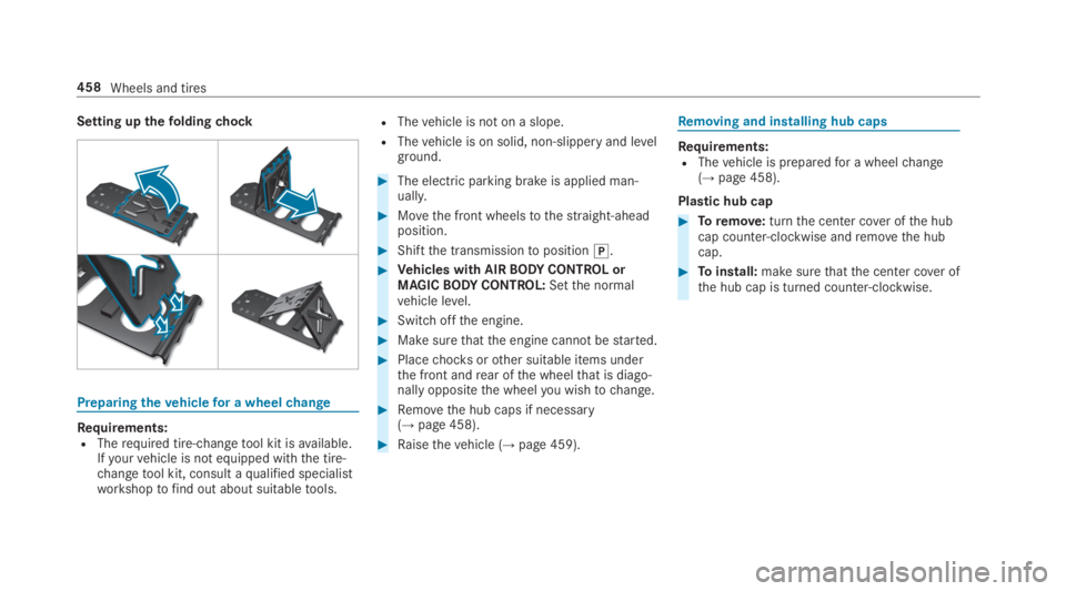
Setting upthefoldingchock
Preparingthevehiclefor a wheelchange
Requirements:RTherequired tire-changetool kit isavailable.Ifyourvehicle is not equipped withthe tire-changetool kit, consult aqualified specialistworkshoptofind out about suitabletools.
RThevehicle is not on a slope.
RThevehicle is on solid, non-slippery and levelground.
#The electric parking brake is applied man‐ually.
#Movethe front wheelstothestraight-aheadposition.
#Shiftthe transmissiontoposition�].
#Vehicles with AIRBODYCONTROL orMAGICBODYCONTROL:Setthe normalvehicle level.
#Switchoffthe engine.
#Make surethatthe engine cannotbestarted.
#Placechocksorother suitable items underthe front andrear ofthe wheelthat is diago‐nally oppositethe wheelyou wishtochange.
#Removethe hub caps if necessary(→page 458).
#Raisethevehicle (→page 459).
Removing and installing hub caps
Requirements:RThevehicle is preparedfor a wheelchange(→page 458).
Plastic hub cap
#Toremove:turnthe center cover ofthe hubcap counter-clockwise andremovethe hubcap.
#Toinstall:make surethatthe center cover ofthe hub cap is turned counter-clockwise.
458Wheels and tires
Page 467 of 578

1Frontroof area
2Rearroof area
3Rearfenders
4Trunk lid
Onvehicles with a panoramic sliding sunroof,installing an antennatothe front orrearroofarea is not permitted.
Ontherearfenders, it isrecommendedthatyouinstallthe antenna onthe side ofthevehicleclosesttothe center oftheroad.
UseTechnical Specification ISO/TS21609 (RoadVehicles – "EMCsfor installation of aftermarketradio frequency transmitting equipment") whenretrofitting two-wayradios. Comply withthelegalrequirementsfor detachable parts.
Ifyourvehicle has installationsfor two-wayradioequipment, usethe power supplyand antennaconnectorsprovided inthe pre-installation.Observethe manufacturer's supplements wheninstalling.
Two-wayradio transmission outputThe maximum transmission output (PEAK) atthebase ofthe antenna must notexceedthevaluesinthefollowingtable:
Frequency band and maximum transmissionoutput
Frequency band Maximum transmis‐sion output
Shortwave
3 -54MHz
100 W
4 m frequency band
74-78MHz
30 W
2 m frequency band
144 -174 MHz
50 W
trunkedradio sys‐tem/Tetra
380 - 460 MHz
10 W
70 cm frequencyband
400 - 460 MHz
35 W
Two-wayradio(2G/3G/4G)10 W
Technical data465
Page 468 of 578

Thefollowing can be used inthevehicle withoutrestrictions:
RRF transmitters witha maximum transmis‐sion output of upto100 mW
RRF transmitters with transmitter frequenciesinthe 380 -410 MHz frequency band and amaximum transmission output of upto2 W(trunkedradio system/Tetra)
Rmobile phones (2G/3G/4G)
There are norestrictions when positioningtheantenna onthe outside ofthevehiclefor somewavebands.
This appliestothefollowingwavebands:
Rtrunkedradio system/Tetra
R70 cm frequency band
R2G/3G/4G
Vehicle identification plate, VIN and enginenumberoverview
Vehicle identification plate
Vehicle identification plate (USA only)
1Permissiblegrossweight
2Permissible front axle load
3Permissiblerear axle load
4Paint code
5VIN (vehicle identification number)
466Technical data
Page 511 of 578
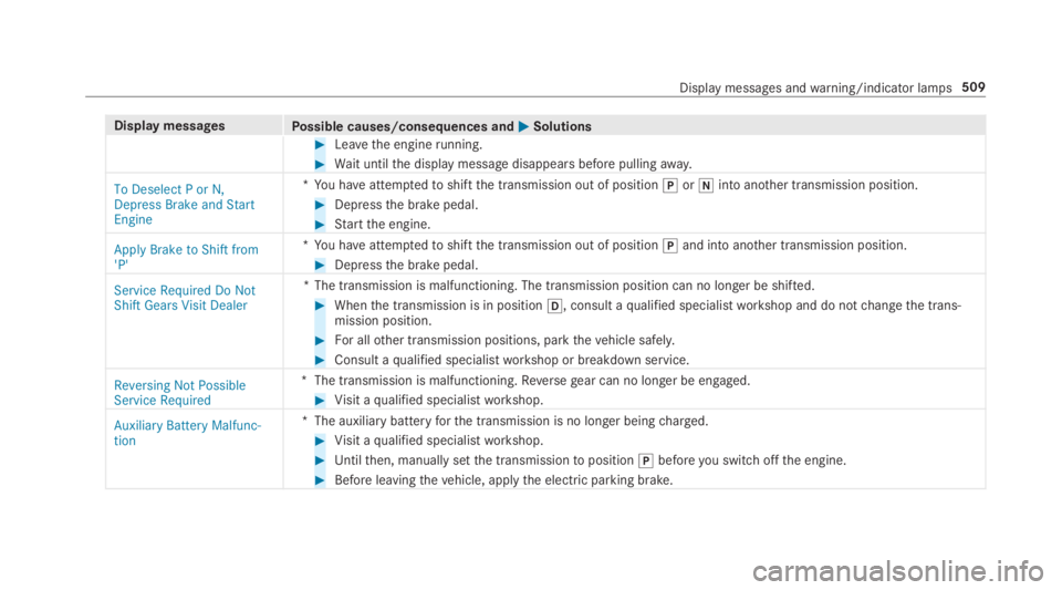
Display messagesPossible causes/consequences and�P�PSolutions
#Leavethe enginerunning.
#Wait untilthe display message disappears before pullingaway.
To Deselect P or N,Depress Brake and StartEngine
*You haveattemptedtoshiftthe transmission out of position�]or�\\into another transmission position.
#Depressthe brake pedal.
#Startthe engine.
Apply Brake to Shift from'P'
*You haveattemptedtoshiftthe transmission out of position�]and into another transmission position.
#Depressthe brake pedal.
Service Required Do NotShift Gears Visit Dealer
*The transmission is malfunctioning. The transmission position can no longer be shifted.
#Whenthe transmission is in position�[, consult aqualified specialistworkshop and do notchangethe trans‐mission position.
#For allother transmission positions, parkthevehicle safely.
#Consult aqualified specialistworkshop or breakdown service.
Reversing Not PossibleService Required
*The transmission is malfunctioning.Reversegear can no longer be engaged.
#Visit aqualified specialistworkshop.
Auxiliary Battery Malfunc-tion
*The auxiliarybatteryforthe transmission is no longer beingcharged.
#Visit aqualified specialistworkshop.
#Untilthen, manually setthe transmissiontoposition�]beforeyou switchoffthe engine.
#Before leavingthevehicle, applythe electric parking brake.
Display messages andwarning/indicator lamps509
Page 512 of 578
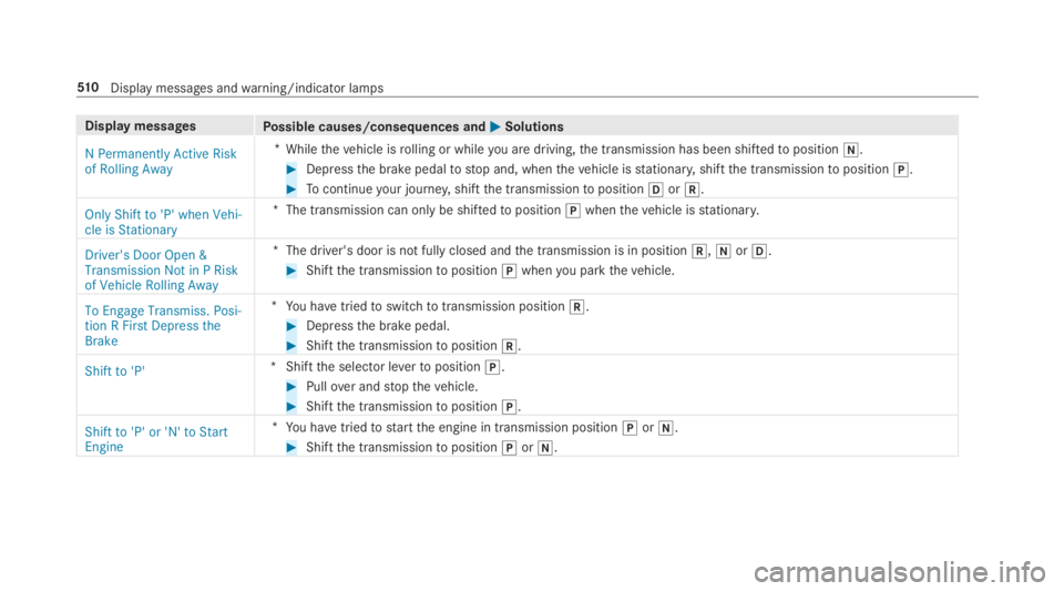
Display messagesPossible causes/consequences and�P�PSolutions
N Permanently Active Riskof Rolling Away
*Whilethevehicle isrolling or whileyou are driving,the transmission has been shiftedtoposition�\\.
#Depressthe brake pedaltostop and, whenthevehicle isstationary,shiftthe transmissiontoposition�].
#Tocontinueyour journey,shiftthe transmissiontoposition�[or�^.
Only Shift to 'P' when Vehi-cle is Stationary
*The transmission can only be shiftedtoposition�]whenthevehicle isstationary.
Driver's Door Open &Transmission Not in P Riskof Vehicle Rolling Away
*The driver's door is not fully closed andthe transmission is in position�^,�\\or�[.
#Shiftthe transmissiontoposition�]whenyou parkthevehicle.
To Engage Transmiss. Posi-tion R First Depress theBrake
*You havetriedtoswitchtotransmission position�^.
#Depressthe brake pedal.
#Shiftthe transmissiontoposition�^.
Shift to 'P'*Shiftthe selector levertoposition�].
#Pullover andstopthevehicle.
#Shiftthe transmissiontoposition�].
Shift to 'P' or 'N' to StartEngine
*You havetriedtostartthe engine in transmission position�]or�\\.
#Shiftthe transmissiontoposition�]or�\\.
51 0Displaymessages andwarning/indicator lamps
Page 541 of 578
Assistance systemssee Driving safety system
Assistant displayMenu (on-board computer) .................. 256
ASSYST PLUS........................................... 395Battery disconnection periods .............396Displayingthe service due date ........... 395Function/notes ................................... 395Regular maintenancework.................. 395Special servicerequirements .............. 395
ATA(anti-theft alarmsystem).................. 90Deactivatingthe alarm ...........................91Function ................................................ 90
ATTENTION ASSIST.......................... 237, 238Function .............................................. 237Setting ................................................. 238System limitations ...............................237
Attention assistantseeATTENTION ASSIST
Audio modeActivating media mode ........................ 355Connecting USB devices ..................... 358Copyrights ...........................................355Information .......................................... 354
Inserting/removing an SD card ........... 355Media search ....................................... 361Overview ............................................. 357Pause and playback function ...............358Selecting a track ................................. 358Selecting playbackoptions .................. 358Track list .............................................. 358
Authorized Mercedes-Benz Centersee Qualified specialistworkshop
Authorizedworkshopsee Qualified specialistworkshop
Automatic activationSwitching on/off.................................24 2
Automatic distance controlseeActive Distance AssistDISTRONIC
Automatic driving lights.........................14 6
Automatic enginestart (ECOstart/stop function)..........................................173
Automatic enginestop (ECOstart/stop function)..........................................173
Automatic front passenger front air‐bag shutoff...........................................41, 43Function ofthe automatic frontpassenger front airbag shutoff ...............41PASSENGER AIRBAG indicator lamp .....43
Automatic front passenger front air‐bag shutoffseeAutomatic front passenger frontairbag shutoff
Automatic lateral support adjustmentSetting .................................................109
Automatic mirrorfolding functionActivating/deactivating .......................157
Automatic transmissionDIRECT SELECT lever ...........................17 7Drive program display ..........................176Drive programs ....................................175DYNAMIC SELECT switch .....................175Engaging drive position ........................178Engaging neutral ..................................178Engaging parkposition ........................178Engagingreversegear .........................178Kickdown .............................................180Manualgearshifting .............................178
Index539
Page 542 of 578

Steering wheel paddle shifters............178Transmission position display ..............17 7Transmission positions ........................17 7
B
BAS (Brake Assist System).....................192
BatteryCharging (RemoteOnline) ....................17 0SmartKey...............................................64
Batterysee Battery (vehicle)
Battery (vehicle)...................................... 424Charging .............................................. 423Charging (RemoteOnline) ....................17 0Notes ...................................................419Notes (starting assistance andcharging) .............................................421Replacing .............................................424Starting assistance .............................. 423
Beltsee Seat belt
Belt airbagActivation .............................................. 32Function/notes .....................................36
Blind Spot Assist.....................................24 3Function ..............................................24 3Switching on/off .................................24 6System limitations ...............................243
Blu-raydrive (Rear Seat Entertain‐ment System)Overview .............................................383
Bluetooth®............................................... 290Activating/deactivating .......................290Information .......................................... 289
Bluetooth®audioActivating ............................................ 366De-authorizing (de-registering)thedevice .................................................. 366Information .......................................... 364Overview .............................................364Searchingfor a track ........................... 366Searchingfor and authorizingthedevice .................................................. 365Selecting a media player .....................366Switching device via NFC .................... 366
Brake Assist SystemseeBAS (Brake AssistSystem)
BrakefluidNotes ...................................................472
Brakeforce distributionEBD (electronic brakeforce distribu‐tion) .....................................................19 6
BrakesABS (Anti-lockBraking System) ...........19 2Active Brake Assist..............................19 6BAS (Brake AssistSystem) ..................19 2Driving tips ..........................................171EBD (electronic brakeforce distribu‐tion) .....................................................19 6HOLD function .....................................214Limited braking effect (salt-treatedroads) ..................................................171New/replaced brakepads/brakediscs ....................................................17 0Notes on breaking-in a newvehicle .....17 0
Braking assistanceseeBAS (Brake AssistSystem)
BreakdownChanging a wheel ................................ 458Overview ofthe help functions ..............16Roadside Assistance ..............................21
540Index
Page 545 of 578
Air distribution settings ........................161Air-recirculation mode .........................162Automatic control (front) .....................160Automatic control (rear passengercompartment) ......................................161Climatestyle function ..........................161Control panelfor 3-zone automaticclimatecontrol ....................................15 9Filling capacityforPAG oil ...................475Front airvents .....................................16 5Glovebox airvent ................................16 6Inserting/removingtheflacon (fra‐grance system) ....................................16 3Ionization .............................................16 3Note....................................................15 9Rear airvents ......................................16 5Rear operating unit ..............................15 9Rear passenger compartmentresid‐ual heat ...............................................16 3Refrigerant ...........................................474Refrigerantfilling capacity ...................475Removing condensation fromthewindows..............................................16 2Residual heat inthe front compart‐ment ....................................................163
Settingrear climate control (multi‐media system) .....................................162Settingthe climatestyle ......................161Settingthe fragrance system ...............16 3Switching on/off (front) ......................16 0Switching on/off (rear passengercompartment) ......................................16 0Ventilatingthevehicle (convenienceopening) ................................................ 79Windshield heater ................................16 4
ClimatestyleFunction ...............................................161Setting .................................................161
Cockpit.........................................................6Overview .................................................6
Coffee cup symbolseeATTENTION ASSIST
COMANDsee Multimedia system
COMANDTouchManaging devices ................................ 292
Combination switch................................14 6
Compass.................................................. 325
Computersee On-board computer
ConnectionstatusDisplaying ............................................ 350Overview .............................................349
ConnectivitySwitching transmission ofthevehicleposition on/off .................................... 289
Contacts................................................... 334Calling up ............................................ 335Deleting ............................................... 336Downloading (from mobile phone) ...... 334Importing ............................................ 335Importing (overview) ...........................335Information .......................................... 334Making a call ....................................... 336Nameformat .......................................335Options ................................................ 336Storing ................................................ 336
ControllerOperating ............................................ 280
Convenience closingfeature.................... 80
Convenience opening................................ 79
Index543