2019 MERCEDES-BENZ S CLASS radio
[x] Cancel search: radioPage 467 of 578

1Frontroof area
2Rearroof area
3Rearfenders
4Trunk lid
Onvehicles with a panoramic sliding sunroof,installing an antennatothe front orrearroofarea is not permitted.
Ontherearfenders, it isrecommendedthatyouinstallthe antenna onthe side ofthevehicleclosesttothe center oftheroad.
UseTechnical Specification ISO/TS21609 (RoadVehicles – "EMCsfor installation of aftermarketradio frequency transmitting equipment") whenretrofitting two-wayradios. Comply withthelegalrequirementsfor detachable parts.
Ifyourvehicle has installationsfor two-wayradioequipment, usethe power supplyand antennaconnectorsprovided inthe pre-installation.Observethe manufacturer's supplements wheninstalling.
Two-wayradio transmission outputThe maximum transmission output (PEAK) atthebase ofthe antenna must notexceedthevaluesinthefollowingtable:
Frequency band and maximum transmissionoutput
Frequency band Maximum transmis‐sion output
Shortwave
3 -54MHz
100 W
4 m frequency band
74-78MHz
30 W
2 m frequency band
144 -174 MHz
50 W
trunkedradio sys‐tem/Tetra
380 - 460 MHz
10 W
70 cm frequencyband
400 - 460 MHz
35 W
Two-wayradio(2G/3G/4G)10 W
Technical data465
Page 468 of 578

Thefollowing can be used inthevehicle withoutrestrictions:
RRF transmitters witha maximum transmis‐sion output of upto100 mW
RRF transmitters with transmitter frequenciesinthe 380 -410 MHz frequency band and amaximum transmission output of upto2 W(trunkedradio system/Tetra)
Rmobile phones (2G/3G/4G)
There are norestrictions when positioningtheantenna onthe outside ofthevehiclefor somewavebands.
This appliestothefollowingwavebands:
Rtrunkedradio system/Tetra
R70 cm frequency band
R2G/3G/4G
Vehicle identification plate, VIN and enginenumberoverview
Vehicle identification plate
Vehicle identification plate (USA only)
1Permissiblegrossweight
2Permissible front axle load
3Permissiblerear axle load
4Paint code
5VIN (vehicle identification number)
466Technical data
Page 514 of 578

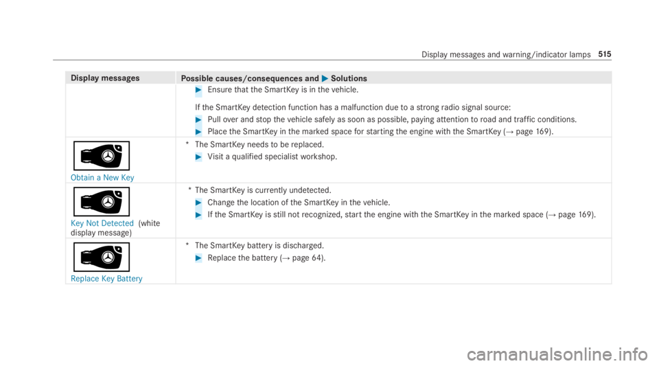
Display messagesPossible causes/consequences and�P�PSolutions
&WARNINGRisk of an accident duetoinsufficient tire pressure
Tirepressuresthat aretoo low posethefollowing hazards:
RThe tires may burst, especially asthe load andvehicle speed increase.
RThe tires maywearexcessively and/or unevenly,which may greatly impair tire traction.
RThe drivingcharacteristics, aswell assteering and braking, may be greatly impaired.
You couldthen lose control ofthevehicle.
#Observetherecommended tire pressure.
#Adjustthe tire pressure if necessary.
#Stopthevehicle, paying attentiontoroad and traffic conditions.
#Checkthe tire pressure (→page 435) andthe tires.
�w
Please Correct Tire Pres-sure
*The tire pressure istoo low in at least one ofthe tires, orthe tire pressure difference betweenthe wheels istoogreat.
#Checkthe tire pressure and add air, if necessary.
#Whenthe tire pressure is correct,restartthe tire pressure monitoring system (→page441).
�w
*There is interference from a powerfulradio signal source. As aresult, no signals fromthe tire pressure sensor arereceived. The tire pressure monitoring system istemporarily unavailable.
512Displaymessages andwarning/indicator lamps
Page 517 of 578

Display messagesPossible causes/consequences and�P�PSolutions
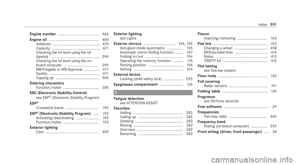
#Ensurethatthe SmartKeyis inthevehicle.
Ifthe SmartKeydetection function has a malfunction duetoastrongradio signal source:
#Pullover andstopthevehicle safely as soon as possible, paying attentiontoroad and traffic conditions.
#Placethe SmartKeyinthe marked spaceforstartingthe engine withthe SmartKey (→page169).
�
Page 553 of 578

Engine number........................................ 466
Engine oil.................................................400Additives ..............................................470Capacity ...............................................471Checkingthe oil level usingthe oildipstick ............................................... 399Checkingthe oil level usingthe on-board computer ................................... 399MB-Freigabe or MB-Approval ...............471Quality .................................................471Topping up ...........................................400
EnteringcharactersFunction/notes ................................... 285
ESC (ElectronicStability Control)
see ESP®(ElectronicStability Program)
ESP®
Crosswind Assist .................................19 5
ESP®(ElectronicStability Program)......19 3Activating/deactivating .......................195Function/notes ...................................19 3
Exterior lightingCare .................................................... 409
Exterior lightingsee Lights
Exterior mirrors...............................154,15 5Anti-glaremode (automatic) ................155Automatic mirrorfolding function ........157Folding in/out .....................................154Operatingthe memory function ...........11 5Parking position ...................................156Setting .................................................154
External deviceLocking (child safety lock) ...................293
Eyeglasses compartment.......................124
F
Fatigue detectionseeATTENTION ASSIST
FavoritesAdding .................................................283Calling up ............................................ 282Deleting ............................................... 283Moving ................................................ 283Overview ............................................. 282Renaming ............................................ 283
FlaconInserting/removing .............................16 3
Flat tire.....................................................413Changing a wheel ................................ 458MOExtended tires ................................41 4Notes ...................................................413TIREFIT kit ............................................41 5
FlattowingseeTow-bar system
Floor mats................................................14 3
Foil coveringRadar sensors ......................................191
Folding table............................................124
FragranceseePerfume atomizer
Free software............................................ 29
FrequenciesTwo-wayradio ...................................... 465
Frequency bandDialing (on-board computer) ................ 259
Front airbag (driver, front passenger).....38
Index551
Page 554 of 578

Front passenger headrestraintInstalling/removing (chauffeurmode) ..................................................101
Front passenger seatAdjusting fromthe driver's seat ............ 95Adjusting fromtherear passengercompartment ........................................ 95Installing/removingthe headrestraint (chauffeur mode) ...................101
Fuel...........................................................470Additives ..............................................470E10 ...................................................... 469Fuelreserve.........................................470Gasoline .............................................. 469Quality (gasoline) ................................ 469Refueling .............................................180sulfur content ...................................... 469Tank content ........................................470
Fuel consumptionOn-board computer .............................257
Function seatsee Door control panel
Function seat (rear passenger com‐partment)see Seat (rear passenger compartment)
Fuse insertseeFuses
Fuses........................................................ 430Beforereplacing a fuse ........................ 430Dashboard fuse box ............................ 432Fuse assignment diagram ...................430Fuse box inthe engine compartment .. 431Fuse box inthe front-passengerfoot‐well ...................................................... 432Fuse box inthe trunk ........................... 433Notes .................................................. 430
FusesseeFuses
G
Garage door openerClearingthe memory ...........................187Opening or closingthe door ................186Programming buttons ..........................184Radio equipment approval numbers ....187Resolving problems .............................186
Synchronizingtherolling code .............185
Gasstation searchStarting automatic search................... 305Switching automatic search on/off ......311Using automatic search.......................311
Gasoline...................................................469
Gearshiftrecommendation....................17 9
Genuine parts............................................19
Glassroofsee MAGIC SKYCONTROL
Glide mode...............................................180
GloveboxAirvent ................................................16 6Locking/unlocking ..............................12 3
H
Handbrakesee Electric parking brake
Handlingcharacteristics (unusual)....... 434
HANDS-FREEACCESS................................73
Hazardwarning lights.............................147
552Index
Page 556 of 578

Selecting ..............................................176
Insiderearview mirrorsee Exterior mirrors
Inspectionsee ASSYSTPLUS
Instrument clustersee Instrument Display
Instrument cluster lighting.................... 255
Instrument Display.................................. 251Adjustingthe lighting .......................... 255Function/notes .................................... 251Instrument cluster ................................... 8Settingthe additionalvaluerange ....... 254Warning/indicator lamps .................... 523
Intelligent Light SystemAdaptive Highbeam Assist ...................148Cornering light function .......................14 8
Interior lighting.......................................150Ambient lighting ..................................15 0Reading light ........................................15 0Setting .................................................15 0Switch-off delaytime ...........................151
Intermediate destinationCalculating aroute with intermediatedestinations ........................................ 306Entering ............................................... 306Modifying ............................................ 306Starting an automaticgasstationsearch................................................. 305Startingthe automatic servicesta‐tion search...........................................312
InternetCalling up aweb page .........................350Closingthe browser ............................352Deleting a bookmark........................... 352Deleting browser data .........................352Managing bookmarks .......................... 352
Internet connectionCommunication module function ........ 349Connectionstatus ...............................349Displayingthe connectionstatus ........ 350Establishing .........................................349Information .......................................... 348Restrictions ......................................... 348
InternetradioCalling up ............................................ 352Deletingstations .................................353
Logging out ......................................... 354Overview ............................................. 353Registering .......................................... 354Savingstations .................................... 353Selecting and connectingtoastation.............................................................353Selectingstream .................................354Setting options .................................... 354Terms of use ........................................354
IonizationActivating/deactivating (multimediasystem) ................................................16 3
iPhone®
see Apple CarPlay™see Mercedes-Benz Link
J
JackStorage location ..................................457
Jump-start connection............................423General notes ...................................... 421
554Index
Page 559 of 578

Massage settingsResetting ..............................................110
Mattefinish (cleaning instructions)...... 405
Maximum loadrating..............................448
Maximum permissible loadCalculationexample ............................444Determining ........................................443
Maximum tire pressure..........................448
MechanicalkeyInserting/removing ...............................64Unlockingthe trunk lid ..........................75
MediaMenu (on-boardcomputer) .................. 260Searching ............................................ 361Starting cinema mode .........................367
Media displayNotes ...................................................278
Media InterfaceActivating ............................................ 362Information .......................................... 361Overview .............................................363
Media modeActivating ............................................ 355
Media playbackOperating (on-board computer) ........... 260
Media searchStarting ................................................ 361
Media sourceSelecting (on-board computer) ............ 260
Memory functionHead-up Display — Calling upstoredsettings ................................................11 5Head-up Display —Storing settings ......11 5Operating .............................................11 5Outside mirrors— Calling upstoredsettings ................................................11 5Outside mirrors—Storing settings .......115Seat — Calling upstored settings .........11 5Seat —Storing settings ........................11 5Steering wheel — Calling up savedsettings ................................................11 5Steering wheel — Saving settings .........11 5
Memory function intherearpassenger compartmentOperatingrear seats ............................11 7Operatingthe front passenger seatandrear seat ........................................11 9
Menu (on-board computer)Assistant display................................. 256Designs ............................................... 254Head-up Display ................................... 261Maintenance ....................................... 256Media .................................................. 260Navigation ........................................... 258Overview ............................................. 252Radio ...................................................259Telephone ............................................ 260Trip ...................................................... 257
Mercedes me connect............................ 344Accident and breakdown manage‐ment .................................................... 345Arranging a service appointment ........ 345Callingthe Mercedes-Benz CustomerCenter ................................................. 344Information .......................................... 343Making a call viatheoverhead con‐trol panel ............................................. 344Service call withthe me button ........... 344Transferred data ..................................345
Mercedes-AMGvehiclesNotes ...................................................167
Index557