2019 MERCEDES-BENZ GLS SUV buttons
[x] Cancel search: buttonsPage 178 of 729
Overview of climate control sy
stems Note
s on climate control An interior air
filter in combination with the pre‐
fi lter in the engine compartment must alw ays be
used so that the air conditioning sy stem, pollu‐
tion le vel monitoring and the air filtration work
cor rectl y.Make sure that thefilter is ins talled
cor rectly and thefilter housing in the engine
compartment is closed cor rectly using the cap
and alw ays tightly sealed when in operation. Use
fi lters recommended and appr ovedby
Mercedes-Benz. Alw ays ha veservice workcar‐
ri ed out at a qualified specialist workshop. THERMATIC control panel
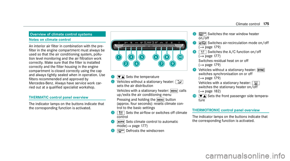
overview The indicator lamps on
the buttons indicate that
th e cor responding function is activated. 1
w Setsthete mp erature
2 Vehicles without a stationary heater: _
sets the air distribution
Ve hicles with a stationary heater: tcalls
up/exits the air conditioning menu
Pressing and holding thet button
(appr ox.fo ur seconds): resets climate con‐
trol tothe basic settings
3 H Setsthe air flow or switches off climate
control
4 Ã Sets climate control toautomatic
mode(/ page177)
5 ¬ Defrosts the windscreen 6
¤ Switches there ar wind owheater
on/off
7 g Switches air-recirculation mode on/off
(/ page 179)
8 Á Switches the A/C function on/off
(/ page 177)
Switches residual heat on or off
(/ page 179)
9 Vehicles without a stationary heater: 0
swit ches synchronisation on or off
(/ page 179)
Ve hicles with a stationary heater: &
swit ches thest ationary heater on/off
(/ page 182)
A w Setsthe front passenger side temp era‐
ture THERMOTRONIC control panel
overview The indicator lamps on
the buttons indicate that
th e cor responding function is activated. Climate
control 175
Page 187 of 729
#
Press and hold theu button.
Setting the departu retime #
Brie fly press theu button. #
Press the, or. button repeatedly
until the time tobe changed appears on the
displa y. #
Press theu and^ buttons simultane‐
ousl y.
The Îsymbol on there mo tecontrol displ ay
fl ashes. #
Press the, and. buttons toset the
desired departure time. #
Press theu and^ buttons simultane‐
ousl y.
The new departure time will be stored.
Up tothre e departure times can be stored. #
Toactivate the departu retime: select the
desired departure time and press and hold
th eu button.
The Ísymbol, the departure time and,
depending on the selected departure time,
th e letter A, BorCappear on the displa y. #
Todeactivate the departure time: select
th e desired departure time and press and
hold the^ button.
OFF will appear on the displa y. #
Tocheck thest atus of thest ationary
heater: briefly press theu button.
Switching off immediately #
Press and hold the^ button.
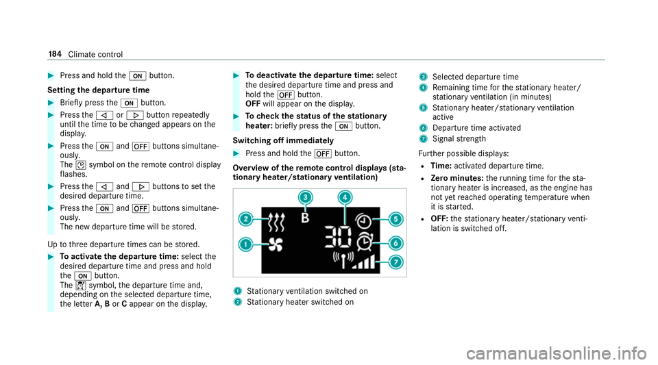
Overview of there mo tecont rol displa ys(sta‐
tiona ryheater/stationary ventilation) 1
Stationary ventilation switched on
2 Stationary heater swit ched on 3
Selected departure time
4 Remaining time forth est ationary heater/
st ationary ventilation (in minu tes)
5 Stationary heater/ stationary ventilation
acti ve
6 Departure time acti vated
7 Signal stre ngth
Fu rther possible displa ys:
R Time: activated departure time.
R Zero minutes: theru nning time forth est a‐
tionary heater is inc reased, as the engine has
not yetre ached operating temp erature when
it is star ted.
R OFF: thest ationary heater/ stationary venti‐
lation is switched off. 184
Climate cont rol
Page 223 of 729
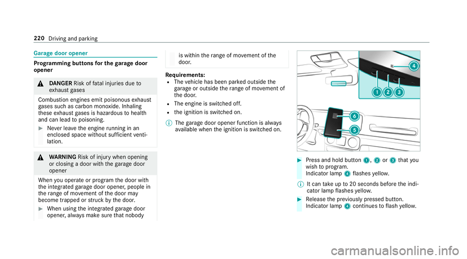
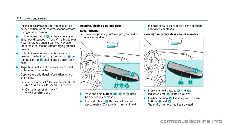
Garage door opener
Prog
ramming buttons for the garage door
opener &
DANG ER Risk of fata l injuries due to
ex haust gases
Combustion engines emit poisonous exhaust
ga ses such as carbon monoxide. Inhaling
th ese exhaust gases is hazardous tohealth
and can lead topoisoning. #
Never lea vethe engine running in an
enclosed space wi thout suf ficient venti‐
lation. &
WARNING Risk of inju rywhen opening
or closing a door with thega rage door
opener
When you operate or program the door with
th e integrated garage door opener, people in
th era nge of mo vement of the door may
become trapped or stru ck bythe door. #
When using the integrated garage door
opener, alw ays make sure that nobody is within
thera nge of mo vement of the
door. Re
quirements:
R The vehicle has been par ked outside the
ga rage or outside thera nge of mo vement of
th e door.
R The engine is switched off.
R the ignition is switched on.
% The garage door opener function is alw ays
av ailable when the ignition is switched on. #
Press and hold button 1,2or3 that you
wish toprog ram.
Indicator lamp 4flashes yello w.
% It can take up to20 seconds before the indi‐
cator lamp flashes yello w. #
Release the pr eviously pressed button.
Indicator lamp 4continues toflash yello w. 220
Driving and parking
Page 224 of 729
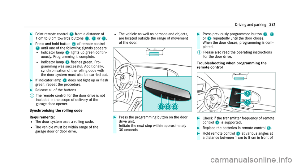
#
Point remo tecontrol 5from a di stance of
1 cm to8 cm towa rds buttons 1,2or3. #
Press and hold button 6ofremo tecontrol
5 until one of thefo llowing signals appears:
R Indicator lamp 4lights up green contin‐
uousl y.Programming is comple te.
R Indicator lamp 4flashes green. Pro‐
gramming was successful. Additionall y,
synchronisation of thero lling code with
th e door sy stem must also be car ried out. #
If indicator lamp 4does not light up or flash
green: repeat the procedure. #
Release all of the buttons.
% The remo tecontrol forth e door drive is not
included in the scope of delivery of the
ga rage door opener.
Synchronising thero lling code
Re quirements:
R The door sy stem uses a rolling code.
R The vehicle must be within range of the
ga rage door or door drive. R
The vehicle as well as persons and objects,
are located outside thera nge of mo vement
of the door. #
Press the programming button on the door
drive unit.
Initiate the next step within appr oximately
30 seconds. #
Press pr eviously prog rammed button 1,2
or 3 repeatedly until the door closes.
When the door closes, programming is com‐
ple ted.
% Please also read the operating instructions
fo rth e door drive.
Tr oubleshooting when prog ramming the
re mo tecont rol #
Check if the transmit ter frequency of remo te
control 5is suppo rted. #
Replace the batteries in remo tecontrol 5. #
Hold remo tecontrol 5atvarious angles at
a dis tance between 1 cm to8 cm in front of Driving and parking
221
Page 225 of 729
th
e inside rearview mir ror.Yo u should test
eve ryposition for at least 25 seconds before
trying ano ther position. #
Hold remo tecontrol 5atthe same angles
at various dis tances in front of the inside rear
view mir ror.Yo u should test eve ryposition
fo r at least 25 seconds before trying ano ther
position. #
Notethat some remo tecontrols transmit
only for a limi ted period, press button 6on
re mo tecontrol 5again before transmission
ends. #
Align the aerial line of the door opener unit
with there mo tecontrol.
% Support and additional information on pro‐
gramming:
R Onthe HomeLink ®
Hotline on (0) 08000
466 354 65 or +49 (0) 6838 907-2 77.
R Onthe Internet at http://
www.homelin k.com. Opening/closing a
garage door
Requ irements:
R The cor responding button is programmed to
operate the door. #
Press and hold buttons 1,2or3 until
th e door opens or closes. #
If indicator lamp 4flashes yellow af ter
appr oximately 20 seconds: press and hold th
e pr eviously pressed button again until the
door opens or closes.
Clearing thega rage door opener memo ry #
Press and hold buttons 1and 3.
Indicator lamp 4lights up yello w. #
If indicator lamp 4flashes green: release
buttons 1and 3.
The entire memo ryhas been dele ted. 222
Driving and parking
Page 244 of 729
R
If pedestrians or vehicles mo vequickly into
th e sensor de tection range.
R If pede strians are hidden by other objects.
R Ifth e typical outline of a pedestrian cann ot
be distinguished from the bac kground.
R If a pedestrian is not de tected as su ch, e.g.
due tospecial clo thing or other objects.
R On bends with a tight radius. Setting
Active Brake Assi st Requ
irements:
R The ignition is switched on.
Multimedia sy stem:
4 © 5
Settings 5
Assistance
5 Active Brake Assist
The following settings are available:
R Early
R Medium
R Late #
Select a setting.
The setting is retained when the engine is
next star ted.
Deactivating Active Brake Assi st
% It is recommended that you alw ays lea ve
Ac tive Brake Assi stactivated. #
Select Off.
The dis tance warning function, the autono‐
mous braking function and the Evasive Steer‐
ing Assist are deactivated.
When theve hicle is next star ted, the middle
setting is automatically selected.
% IfAc tive Brake Assi stis deactivated, the
æ symbol appears inthest atus bar of the
multifunction displa y. Fu
nction of Adaptive Brake Lights Ad
aptive Brake Lights warnfollowing traf fic in an
emergency braking situation wi th thefo llowing
actions:
R Byflashing the brake lamps
R By activating the hazard warning lights If
th eve hicle is braked sharply from speeds
abo ve50 km/h, the brake lamps flash rapidl y.
This pr ovides traf fic tr avelling behind you with an
ev en more noticeable warning.
If th eve hicle is tr avelling at speeds of more than
70 km/h at the beginning of the brake applica‐
tion, the hazard warning lights switch on once
th eve hicle is stationar y.When you pull away
again, the hazard warning lights will switch off
automatically at appr oximately 10km/h. Yo u
can also switch off the hazard warning lights
using the hazard warning button. Cruise control and limiter
Fu
nction of cruise control
Cruise cont rolre gulates the speed totheva lue
selec tedby the driver.
If yo u accelerate toove rtake, forex ample, the
st ored speed is not dele ted. If youre mo veyour
fo ot from the accelera tor pedal af terov ertaking,
cruise control will resume speed regulation back
to thestored speed.
Cruise contro l is operated using the cor respond‐
ing steering wheel buttons. You can store any Driving and parking
241
Page 246 of 729
The
variable limiter is operated using the cor re‐
sponding steering wheel buttons. You can store
any speed abo ve20 km/h up tothe maximum
speed or up tothe set winter tyre limit. You can
also per form settings while theve hicle is station‐
ary if theve hicle has been star ted.
If yo ufa ilto adapt your driving style, the limiter
can neither reduce therisk of an accident nor
ove rride the la wsof ph ysics. It cannot take into
account road, weather or traf fic conditions. The
limiter is only an aid. You are responsible for
maintaining a safe dis tance totheve hicle in
front, forve hicle speed, for braking in good time
and forst ay ing in lane.
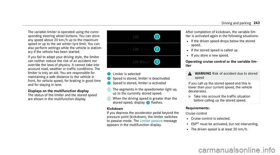
Displa yson the multifunction display
The status of the limiter and thestored speed
are shown in the multifunction displa y. 1
Limiter is selected
2 Speed is stored, limiter is deactivated
3 Speed is stored, limiter is activated
% The segments in the speedome ter light up,
up tothe cur rently stored speed.
% When the driving speed is greater than the
st ored speed, display 3flashes.
Kickd own
If yo u depress the accelerator pedal be yond the
pressure point (kickdown), the limiter switches
to passive mode. The Limiter passivemessage
appears in the multifunction displa y.Af
ter completion of kickdown, theva riable lim‐
iter is activated again in thefo llowing situations:
R Ifth e driven speed drops below thestored
speed.
R Ifth estored speed is called up.
R Ifyo ustore a new speed.
Operating cruise control or theva riable lim‐
iter &
WARNING Risk of accident due tostored
speed
If yo u call up thestored speed and this is
lo we rth an your cur rent speed, theve hicle
decelerates. #
Take into account the tra ffic situation
before calling up thestored speed. Re
quirements:
Cruise control
R Cruise control is selected.
R ESP ®
must be activated, but not inter vening.
R The driven speed is at least 20 km/h. Driving and pa
rking 243
Page 355 of 729
Overview and operation
Overview of
the MBUX multimedia sy stem &
WARNING Risk of di stra ction from infor‐
mation sy stems and communications
equipment
If yo u operate information and communica‐
tion equipment integ rated in theve hicle
when driving, you will be distracted from the
traf fic situation. This could also cause youto
lose control of theve hicle. #
Only operate this equipment when the
traf fic situation permits. #
Ifyo u cannot be sure of this, stop the
ve hicle whilst paying attention toroad
and traf fic conditions and ope rate the
equipment with theve hicle stationar y. Yo
u must obse rveth e legal requirements forthe
country in whi chyou are cur rently driving when
operating the multimedia sy stem.
MBUX stands for Mercedes-Benz User Experi‐
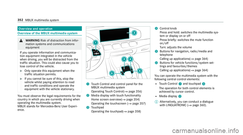
ence. 1
Touch Control and cont rol panel forthe
MBUX multimedia sy stem
Operating Touch Control(/ page 356)
2 Media displ aywith touch functionality
Home sc reen ove rview(/ page 354)
Operating theto uchsc reen (/ page 357)
3 Touchpad
Operating theto uchpad( /page 358) 4
Control knob
Press and hold: swit ches the multimedia sys‐
te m or display on or off
Press brief ly: switches the mute function
on/off
Tu rn: adjusts thevo lume
5 Buttons for navigation, radio/media and
te lephone
Calling up applications(/ page 364)
6 Buttons forve hicle functions/sy stem set‐
tings and favo urites/ themes
Calling up applications(/ page 364)
Yo u can operate the multimedia sy stem with the
fo llowing central control elements:
R Touch Control 1and touchpad 3
The operation for bo thcontrol elements is
achie vedby cursor control.
R Media displ ay2
% Alternati vely, you can conduct a dialogue
with LINGU ATRO NIC (/ page 360). 352
MBUX multimedia sy stem