2019 MERCEDES-BENZ GLS SUV seats
[x] Cancel search: seatsPage 300 of 398
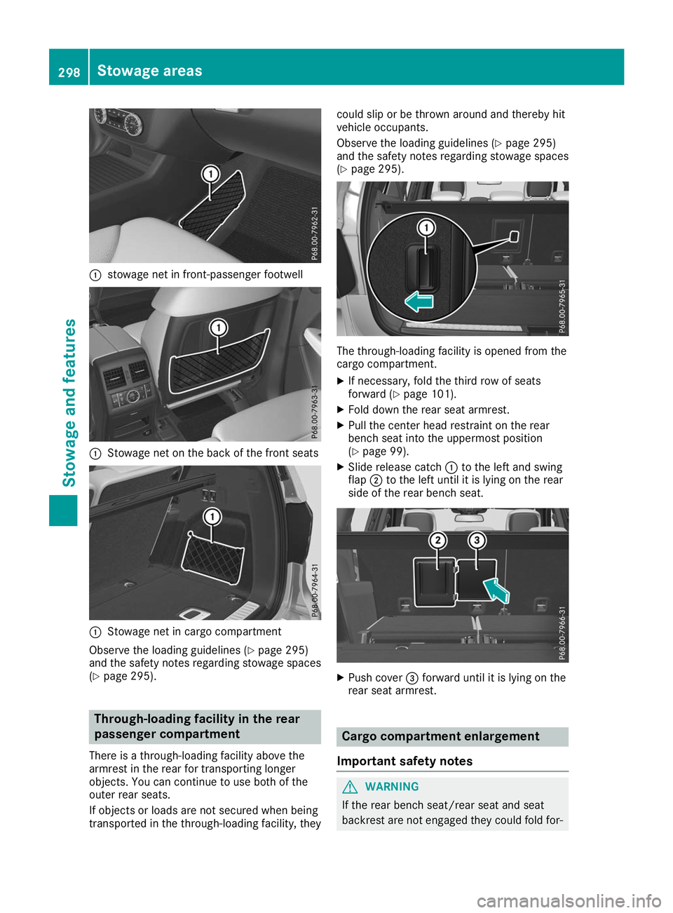
0043
stowage net in front-passenger footwell 0043
Stowage net on the back of the front seats 0043
Stowage net in cargo compartment
Observe the loading guidelines (Y page 295)
and the safety notes regarding stowage spaces
(Y page 295). Through-loading facility in the rear
passenger compartment
There is a through-loading facility above the
armrest in the rear for transporting longer
objects. You can continue to use both of the
outer rear seats.
If objects or loads are not secured when being
transported in the through-loading facility, they could slip or be thrown around and thereby hit
vehicle occupants.
Observe the loading guidelines (Y
page 295)
and the safety notes regarding stowage spaces
(Y page 295). The through-loading facility is opened from the
cargo compartment.
X If necessary, fold the third row of seats
forward (Y page 101).
X Fold down the rear seat armrest.
X Pull the center head restraint on the rear
bench seat into the uppermost position
(Y page 99).
X Slide release catch 0043to the left and swing
flap 0044to the left until it is lying on the rear
side of the rear bench seat. X
Push cover 0087forward until it is lying on the
rear seat armrest. Cargo compartment enlargement
Important safety notes G
WARNING
If the rear bench seat/rear seat and seat
backrest are not engaged they could fold for- 298
Stowage areasStowage and features
Page 301 of 398
wards, e.g. when braking suddenly or in the
event of an accident.
R The vehicle occupant would thereby be
pushed into the seat belt by the rear bench
seat/rear seat or by the seat backrest. The
seat belt can no longer offer the intended
level of protection and could even cause
injuries.
R Objects or loads in the trunk/cargo com-
partment cannot be restrained by the seat
backrest.
There is an increased risk of injury.
Before every trip, make sure that the seat
backrests and the rear bench seat/rear seat
are engaged.
Make sure that the seat backrest and the seat
cushion are correctly engaged in position. To do so, pull firmly on the seat backrest.
! Release and fold the seat cushion upwards
before folding the rear bench seat forward.
Otherwise, the backrests may be damaged.
When the backrest is folded forwards, the
front seats cannot be moved to their rearmost position. Otherwise, the front seats and the
rear bench seat could be damaged.
! The backrest is heavy. Therefore, take care
when folding it down. Make sure that the head restraints are pushed all the way in so that the
backrests and seat cushions are not dam-
aged.
Observe the loading guidelines (Y page 295).
The left-hand and right-hand backrests in the
second row of seats can be folded forward sep-
arately to increase the cargo compartment
capacity.
On vehicles with a third row of seats, you must
fold down the third row of seats beforehand
(Y page 101) to obtain maximum cargo com-
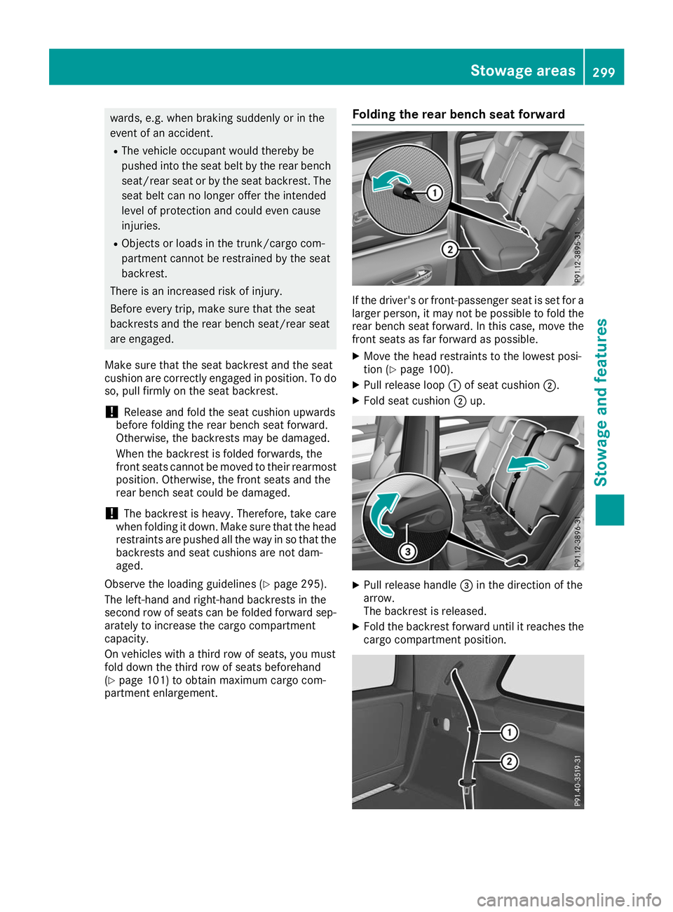
partment enlargement. Folding the rear bench seat forward If the driver's or front-passenger seat is set for a
larger person, it may not be possible to fold the
rear bench seat forward. In this case, move the front seats as far forward as possible.
X Move the head restraints to the lowest posi-
tion (Y page 100).
X Pull release loop 0043of seat cushion 0044.
X Fold seat cushion 0044up. X
Pull release handle 0087in the direction of the
arrow.
The backrest is released.
X Fold the backrest forward until it reaches the
cargo compartment position. Stowage areas
299Stowage and features Z
Page 303 of 398
Cargo compartment cover
Important safety notes G
WARNING
On its own, the cargo compartment cover
cannot secure or restrain heavy objects,
items of luggage and heavy loads. You could
be hit by an unsecured load during sudden
changes in direction, braking or in the event of an accident. There is an increased risk of
injury or even fatal injury.
Always store objects so that they cannot be
flung around. Secure objects, luggage or
loads against slipping or tipping over, e.g. by
using tie downs, even if you are using the
cargo compartment cover.
! When loading the vehicle, make sure that
you do not stack the load in the cargo com-
partment higher than the lower edge of the
side windows. Do not place heavy objects on top of the cargo compartment cover.
The cargo compartment cover may be installed
behind the 2nd or 3rd row of seats.
Extending/retracting the cargo com-
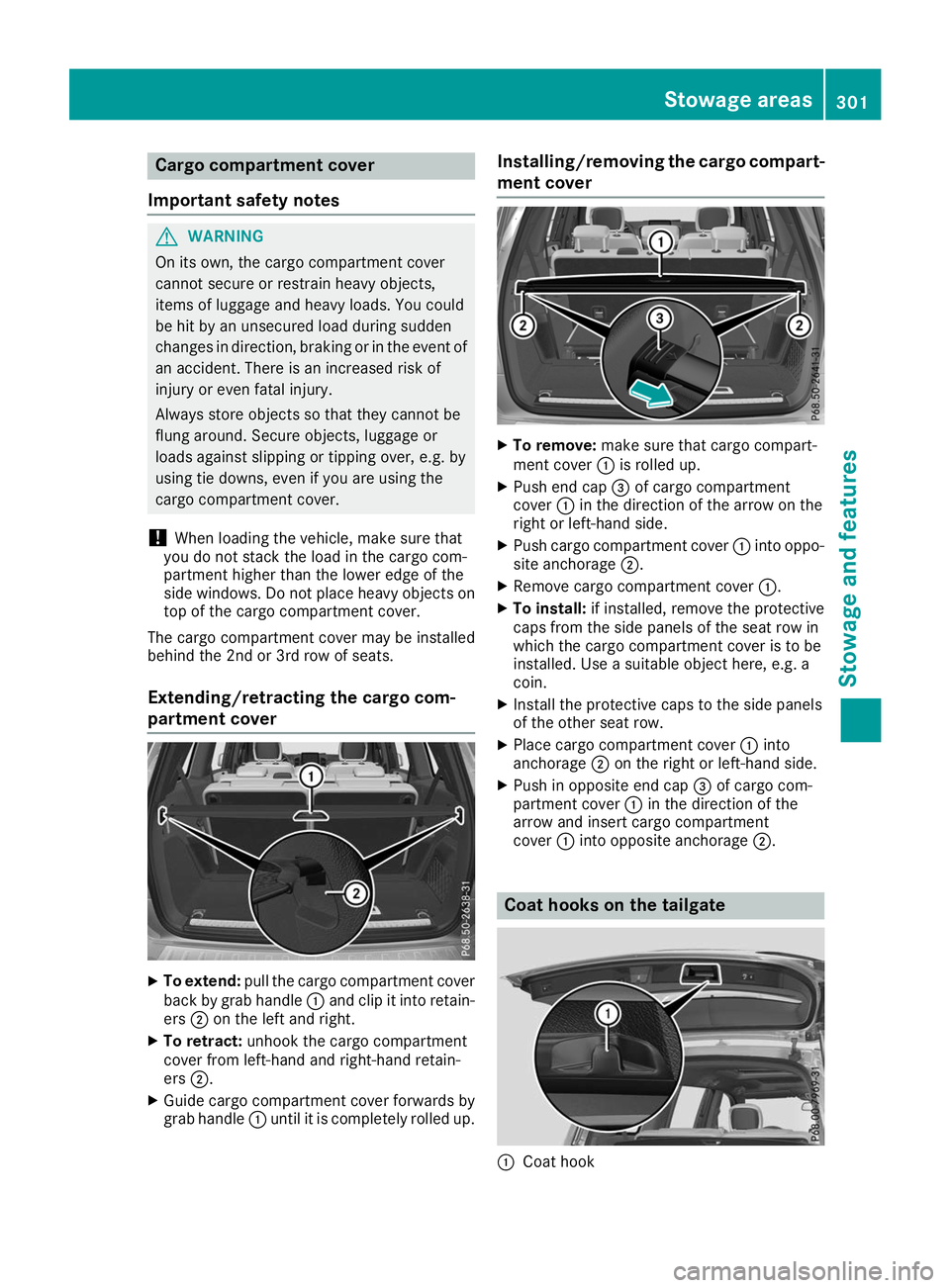
partment cover X
To extend: pull the cargo compartment cover
back by grab handle 0043and clip it into retain-
ers 0044on the left and right.
X To retract: unhook the cargo compartment
cover from left-hand and right-hand retain-
ers 0044.
X Guide cargo compartment cover forwards by
grab handle 0043until it is completely rolled up. Installing/removing the cargo compart-
ment cover X
To remove: make sure that cargo compart-
ment cover 0043is rolled up.
X Push end cap 0087of cargo compartment
cover 0043in the direction of the arrow on the
right or left-hand side.
X Push cargo compartment cover 0043into oppo-
site anchorage 0044.
X Remove cargo compartment cover 0043.
X To install: if installed, remove the protective
caps from the side panels of the seat row in
which the cargo compartment cover is to be
installed. Use a suitable object here, e.g. a
coin.
X Install the protective caps to the side panels
of the other seat row.
X Place cargo compartment cover 0043into
anchorage 0044on the right or left-hand side.
X Push in opposite end cap 0087of cargo com-
partment cover 0043in the direction of the
arrow and insert cargo compartment
cover 0043into opposite anchorage 0044. Coat hooks on the tailgate
0043
Coat hook Stowage areas
301Stowage and features Z
Page 307 of 398
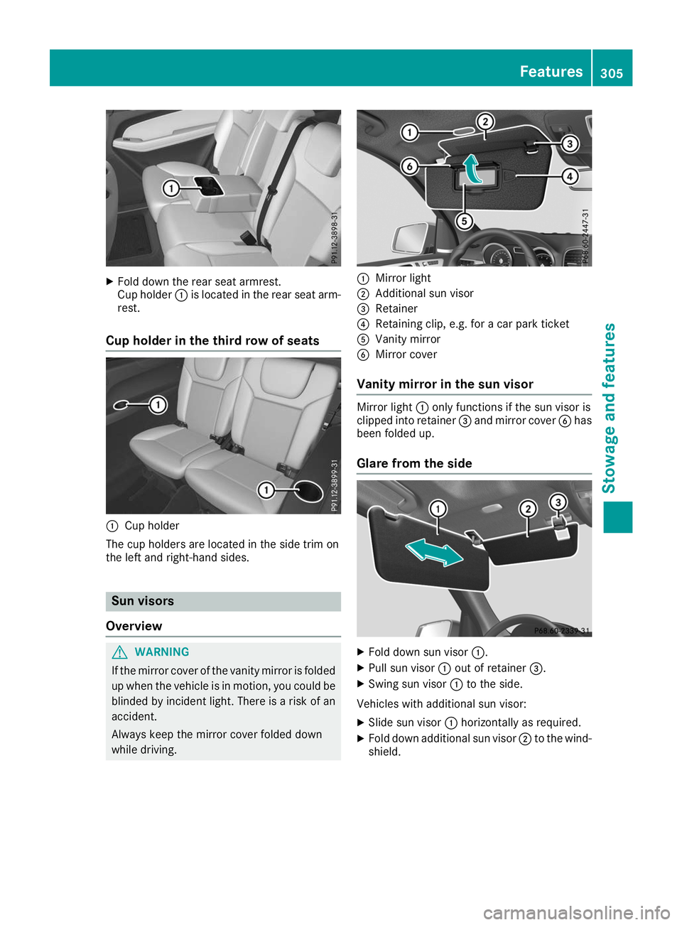
X
Fold down the rear seat armrest.
Cup holder 0043is located in the rear seat arm-
rest.
Cup holder in the third row of seats 0043
Cup holder
The cup holders are located in the side trim on
the left and right-hand sides. Sun visors
Overview G
WARNING
If the mirror cover of the vanity mirror is folded up when the vehicle is in motion, you could be
blinded by incident light. There is a risk of an
accident.
Always keep the mirror cover folded down
while driving. 0043
Mirror light
0044 Additional sun visor
0087 Retainer
0085 Retaining clip, e.g. for a car park ticket
0083 Vanity mirror
0084 Mirror cover
Vanity mirror in the sun visor Mirror light
0043only functions if the sun visor is
clipped into retainer 0087and mirror cover 0084has
been folded up.
Glare from the side X
Fold down sun visor 0043.
X Pull sun visor 0043out of retainer 0087.
X Swing sun visor 0043to the side.
Vehicles with additional sun visor:
X Slide sun visor 0043horizontally as required.
X Fold down additional sun visor 0044to the wind-
shield. Features
305Stowage and features Z
Page 308 of 398
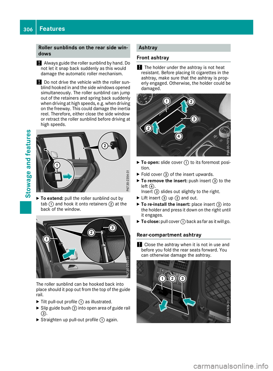
Roller sunblinds on the rear side win-
dows
! Always guide the roller sunblind by hand. Do
not let it snap back suddenly as this would
damage the automatic roller mechanism.
! Do not drive the vehicle with the roller sun-
blind hooked in and the side windows opened simultaneously. The roller sunblind can jump
out of the retainers and spring back suddenly
when driving at high speeds, e.g. when driving on the freeway. This could damage the inertiareel. Therefore, either close the side window
or retract the roller sunblind before driving at
high speeds. X
To extend: pull the roller sunblind out by
tab 0043and hook it onto retainers 0044at the
back of the window. The roller sunblind can be hooked back into
place should it pop out from the top of the guide
rail.
X Tilt pull-out profile 0043as illustrated.
X Slip guide bush 0044into open area of guide rail
0087.
X Straighten up pull-out profile 0043again. Ashtray
Front ashtray !
The holder under the ashtray is not heat
resistant. Before placing lit cigarettes in the
ashtray, make sure that the ashtray is prop-
erly engaged. Otherwise, the holder could be
damaged. X
To open: slide cover 0043to its foremost posi-
tion.
X Fold cover 0087of the insert upwards.
X To remove the insert: push insert0087to the
left 0085.
Insert 0087slides out slightly to the right.
X Lift insert 0087up0044 and out.
X To re-install the insert: place insert0087into
the holder and press it down on the right until
it engages.
X To close: pull cover 0043back as far as it will go.
Rear-compartment ashtray !
Close the ashtray when it is not in use and
before you fold the rear seats forward. You
can otherwise damage the ashtray. 306
FeaturesStowage and features
Page 321 of 398
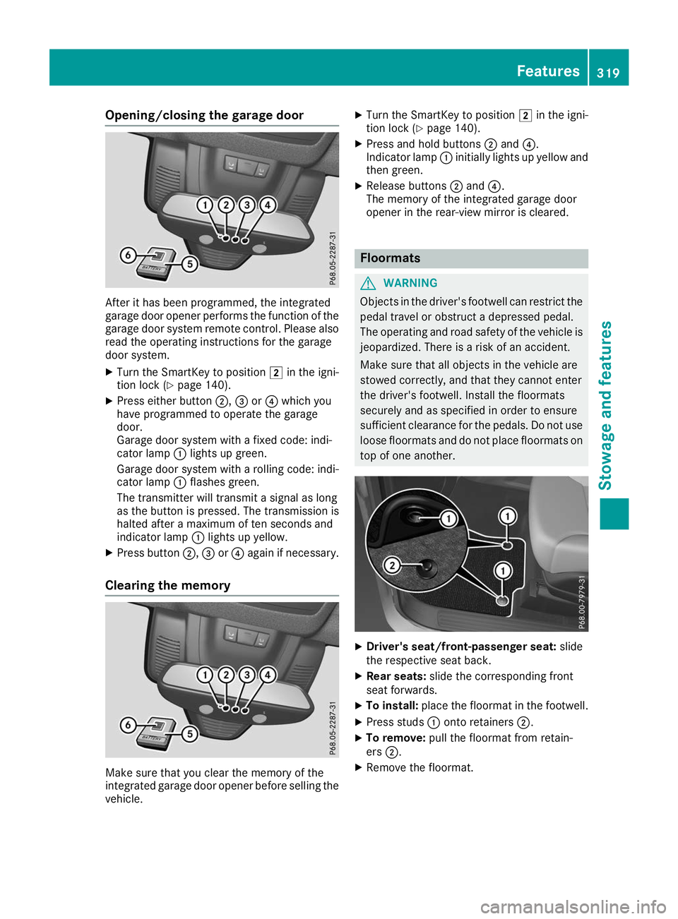
Opening/closing the garage door
After it has been programmed, the integrated
garage door opener performs the function of the
garage door system remote control. Please also
read the operating instructions for the garage
door system.
X Turn the SmartKey to position 0048in the igni-
tion lock (Y page 140).
X Press either button 0044,0087or0085 which you
have programmed to operate the garage
door.
Garage door system with a fixed code: indi-
cator lamp 0043lights up green.
Garage door system with a rolling code: indi-
cator lamp 0043flashes green.
The transmitter will transmit a signal as long
as the button is pressed. The transmission is
halted after a maximum of ten seconds and
indicator lamp 0043lights up yellow.
X Press button 0044,0087or0085 again if necessary.
Clearing the memory Make sure that you clear the memory of the
integrated garage door opener before selling the vehicle. X
Turn the SmartKey to position 0048in the igni-
tion lock (Y page 140).
X Press and hold buttons 0044and 0085.
Indicator lamp 0043initially lights up yellow and
then green.
X Release buttons 0044and 0085.
The memory of the integrated garage door
opener in the rear-view mirror is cleared. Floormats
G
WARNING
Objects in the driver's footwell can restrict the pedal travel or obstruct a depressed pedal.
The operating and road safety of the vehicle is
jeopardized. There is a risk of an accident.
Make sure that all objects in the vehicle are
stowed correctly, and that they cannot enter
the driver's footwell. Install the floormats
securely and as specified in order to ensure
sufficient clearance for the pedals. Do not use loose floormats and do not place floormats on
top of one another. X
Driver's seat/front-passenger seat: slide
the respective seat back.
X Rear seats: slide the corresponding front
seat forwards.
X To install: place the floormat in the footwell.
X Press studs 0043onto retainers 0044.
X To remove: pull the floormat from retain-
ers 0044.
X Remove the floormat. Features
319Stowage and features Z
Page 342 of 398
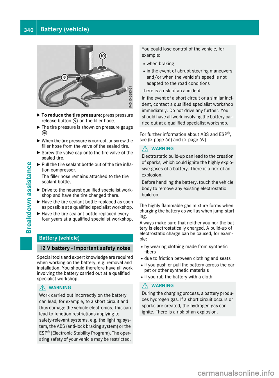
X
To reduce the tire pressure: press pressure
release button 006Don the filler hose.
X The tire pressure is shown on pressure gauge
006E.
X When the tire pressure is correct, unscrew the
filler hose from the valve of the sealed tire.
X Screw the valve cap onto the tire valve of the
sealed tire.
X Pull the tire sealant bottle out of the tire infla-
tion compressor.
The filler hose remains attached to the tire
sealant bottle.
X Drive to the nearest qualified specialist work-
shop and have the tire changed there.
X Have the tire sealant bottle replaced as soon
as possible at a qualified specialist workshop.
X Have the tire sealant bottle replaced every
four years at a qualified specialist workshop. Battery (vehicle)
12 V battery - important safety notes
Special tools and expert knowledge are required
when working on the battery, e.g. removal and
installation. You should therefore have all work
involving the battery carried out at a qualified
specialist workshop. G
WARNING
Work carried out incorrectly on the battery
can lead, for example, to a short circuit and
thus damage the vehicle electronics. This can lead to function restrictions applying to
safety-relevant systems, e.g. the lighting sys- tem, the ABS (anti-lock braking system) or the
ESP ®
(Electronic Stability Program). The oper-
ating safety of your vehicle may be restricted. You could lose control of the vehicle, for
example:
R when braking
R in the event of abrupt steering maneuvers
and/or when the vehicle's speed is not
adapted to the road conditions
There is a risk of an accident.
In the event of a short circuit or a similar inci-
dent, contact a qualified specialist workshop
immediately. Do not drive any further. You
should have all work involving the battery car- ried out at a qualified specialist workshop.
For further information about ABS and ESP ®
,
see (Y page 66) and (Y page 69). G
WARNING
Electrostatic build-up can lead to the creation of sparks, which could ignite the highly explo-
sive gases of a battery. There is a risk of an
explosion.
Before handling the battery, touch the vehicle body to remove any existing electrostatic
build-up.
The highly flammable gas mixture forms when
charging the battery as well as when jump-start- ing.
Always make sure that neither you nor the bat-
tery is electrostatically charged. A build-up of
electrostatic charge can be caused, for exam-
ple:
R by wearing clothing made from synthetic
fibers
R due to friction between clothing and seats
R if you push or pull the battery across the car-
pet or other synthetic materials
R if you rub the battery with a cloth G
WARNING
During the charging process, a battery produ- ces hydrogen gas. If a short circuit occurs or
sparks are created, the hydrogen gas can
ignite. There is a risk of an explosion. 340
Battery (vehicle)Breakdo
wn assis tance
Page 358 of 398
R
incorrectly set tire pressure
R sudden loss of tire pressure, e.g. from a for-
eign object that has penetrated the tire
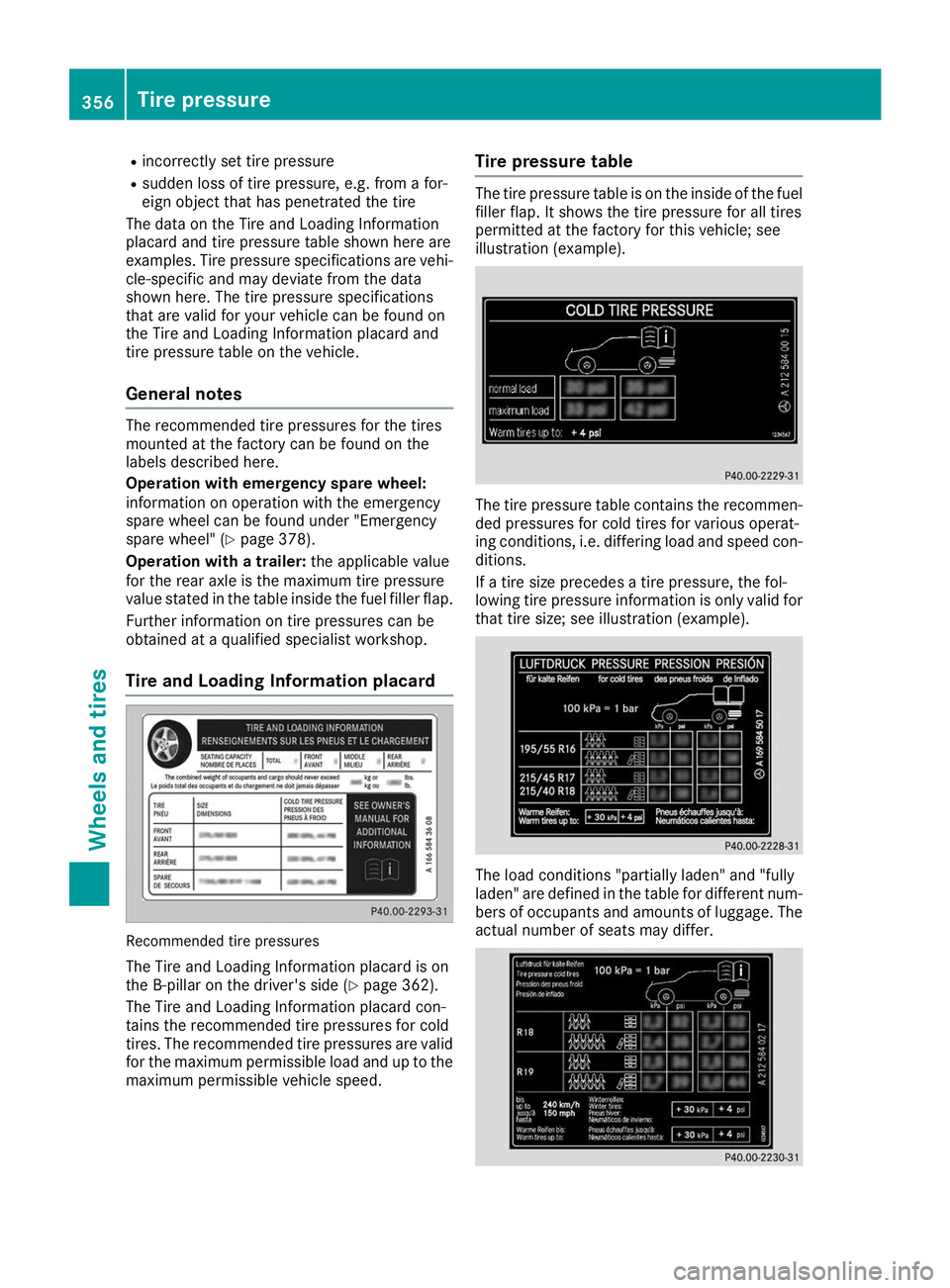
The data on the Tire and Loading Information
placard and tire pressure table shown here are
examples. Tire pressure specifications are vehi- cle-specific and may deviate from the data
shown here. The tire pressure specifications
that are valid for your vehicle can be found on
the Tire and Loading Information placard and
tire pressure table on the vehicle.
General notes The recommended tire pressures for the tires
mounted at the factory can be found on the
labels described here.
Operation with emergency spare wheel:
information on operation with the emergency
spare wheel can be found under "Emergency
spare wheel" (Y page 378).
Operation with a trailer: the applicable value
for the rear axle is the maximum tire pressure
value stated in the table inside the fuel filler flap.
Further information on tire pressures can be
obtained at a qualified specialist workshop.
Tire and Loading Information placard Recommended tire pressures
The Tire and Loading Information placard is on
the B-pillar on the driver's side (Y page 362).
The Tire and Loading Information placard con-
tains the recommended tire pressures for cold
tires. The recommended tire pressures are valid for the maximum permissible load and up to the
maximum permissible vehicle speed. Tire pressure table The tire pressure table is on the inside of the fuel
filler flap. It shows the tire pressure for all tires
permitted at the factory for this vehicle; see
illustration (example). The tire pressure table contains the recommen-
ded pressures for cold tires for various operat-
ing conditions, i.e. differing load and speed con-
ditions.
If a tire size precedes a tire pressure, the fol-
lowing tire pressure information is only valid for that tire size; see illustration (example). The load conditions "partially laden" and "fully
laden" are defined in the table for different num- bers of occupants and amounts of luggage. The
actual number of seats may differ. 356
Tire pressureWheels and tires