2019 MERCEDES-BENZ GLS SUV warning
[x] Cancel search: warningPage 225 of 398
R
Maintain a greater distance from the vehicle
in front than when driving without a trailer.
R Avoid braking abruptly. If possible, brake gen-
tly at first to allow the trailer to run on. Then,
increase the braking force rapidly.
R The values given for gradient-climbing capa-
bilities from a standstill refer to sea level.
When driving in mountainous areas, note that
the power output of the engine and, conse-
quently, the vehicle's gradient-climbing capa- bility, decreases with increasing altitude. Installing the ball coupling
G
WARNING
If the ball coupling is not correctly installed
and secured, it can come loose during the
journey and endanger other road users. There is a risk of an accident and injury.
Always install and secure the ball coupling as
described. Before every journey, ensure that
the ball coupling is secured with the bolt and
the corresponding spring cotter. G
WARNING
If the ball coupling is not installed correctly or not secured with the bolt provided and the
corresponding spring cotter, the trailer may
come loose. There is a risk of an accident.
Always install and secure the ball coupling as
described. Before every journey, ensure that
the ball coupling is secured with the bolt and
the corresponding spring cotter. G
WARNING
If the ball coupling is not installed and secured
correctly the trailer may come loose. There is
a risk of an accident.
Install and secure the ball coupling as descri-
bed in the ball coupling installation instruc-
tions. Make sure that the ball coupling is
installed and secured correctly before every
journey. X
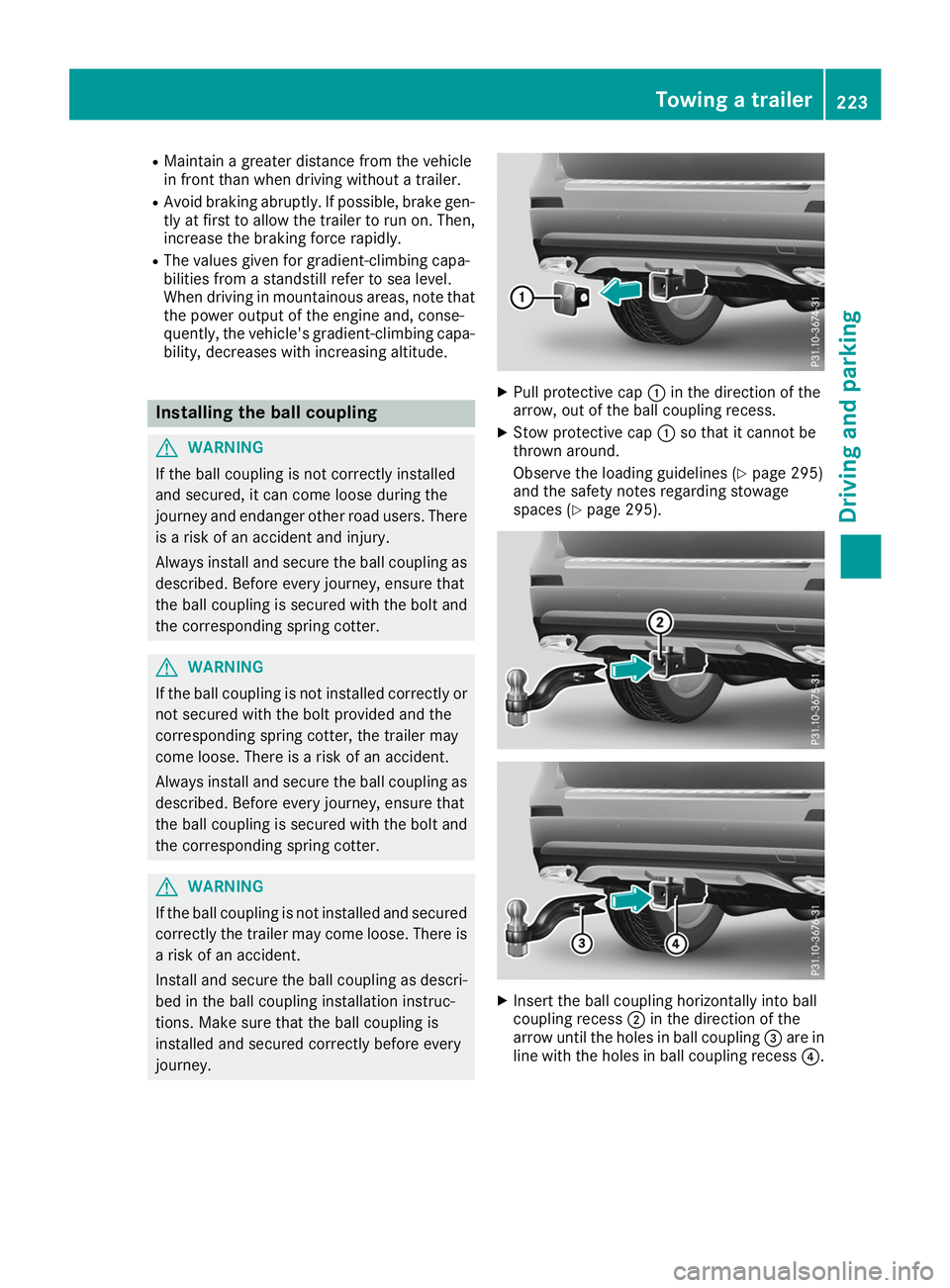
Pull protective cap 0043in the direction of the
arrow, out of the ball coupling recess.
X Stow protective cap 0043so that it cannot be
thrown around.
Observe the loading guidelines (Y page 295)
and the safety notes regarding stowage
spaces (Y page 295). X
Insert the ball coupling horizontally into ball
coupling recess 0044in the direction of the
arrow until the holes in ball coupling 0087are in
line with the holes in ball coupling recess 0085. Towing a trailer
223Driving and parking Z
Page 228 of 398
Decoupling a trailer
G
WARNING
If you uncouple a trailer with the overrun
brake engaged, you could trap your hand
between the vehicle and the trailer drawbar.
There is a risk of injury.
Do not uncouple a trailer if the overrun brake is engaged. G
WARNING
Vehicles with level control:
The vehicle is lowered as soon as you discon-
nect the trailer cable. This could result in your limbs or those of other people that are
between the vehicle body and tires or under-
neath the vehicle being trapped. There is a
risk of injury.
Make sure that nobody is in the immediate
vicinity of the wheel housings or under the
vehicle when you disconnect the trailer cable.
! Do not disconnect a trailer with an engaged
overrun brake. Otherwise, your vehicle could
be damaged by the rebounding of the overrun
brake.
X Shift the transmission to position 005D.
X Apply the vehicle's electric parking brake.
X Start the engine.
X Close the doors and tailgate.
X Apply the trailer's parking brake.
X Detach the trailer cable and decouple the
trailer.
X Switch off the engine. Permissible trailer loads and drawbar
loads
Weight specifications Maximum allowable gross mass
The gross vehicle weight of the trailer is calcu-
lated by adding the weight of the trailer to the
weight of the load and equipment on the trailer.
You will find installing dimensions and loads
under "Technical data" (Y page 392).Permissible noseweight
You will find installing dimensions and loads
under "Technical data" (Y page 392).
Loading a trailer R
When loading the trailer, make sure that nei-
ther the permissible gross weight of the trailer
nor the gross vehicle weight are exceeded.
The permissible gross vehicle weight is indi-
cated on the identification plate located on
the B-pillar on the driver's side of the vehicle.
You can find the maximum permissible values
on the type plates of your vehicle and the
trailer. When calculating how much weight
the vehicle and trailer may carry, pay atten-
tion to the respective lowest values.
R The trailer drawbar load on the ball coupling
must be added to the rear axle load to avoid
exceeding the permissible gross axle weight.
The permissible gross vehicle weight is indi-
cated on the identification plate located on
the B-pillar on the driver's side of the vehicle.
i Mercedes-Benz recommends a trailer load
where the trailer drawbar noseweight
accounts for 8 % to 15 % of the trailer's per-
missible gross weight.
i The weight of additional accessories, pas-
sengers, and cargo reduces the permissible
trailer load and drawbar load for your vehicle.
Checking the vehicle and trailer weight R
To check that the weights of the towing vehi-
cle and the trailer comply with the maximum
permissible values, have the vehicle/trailer
combination (including the driver, passen-
gers, and cargo with a fully laden trailer)
weighed on a calibrated weighbridge.
R Check the gross axle weight rating of the front
and rear axles, the gross weight of the trailer
and the trailer drawbar noseweight. Removing the ball coupling
X Remove the spring cotter.
X Remove the bolt from the ball coupling
recess.
X Remove the ball coupling from the ball cou-
pling recess. 226
Towing a trailerDriving and pa
rking
Page 229 of 398
X
Clean the ball coupling if it is dirty.
X Stow the ball coupling so that it cannot be
thrown around.
Observe the loading guidelines (Y page 295)
and the safety notes regarding stowage spaces
(Y page 295).
Information on cleaning and care of the trailer
tow hitch (Y page 331). Trailer power supply
! Accessories with a maximum power con-
sumption of 180 W can be connected to the
permanent power supply.
You must not charge a trailer battery using the
power supply.
The trailer socket of your vehicle is equipped at
the factory with a permanent power supply.
The permanent power supply is supplied via
trailer socket pin 4.
The trailer's permanent power supply is
switched off in the event of low vehicle supply
voltage and after six hours at the latest.
A qualified specialist workshop can provide
more information about installing the trailer
electrics. Bicycle rack
General notes
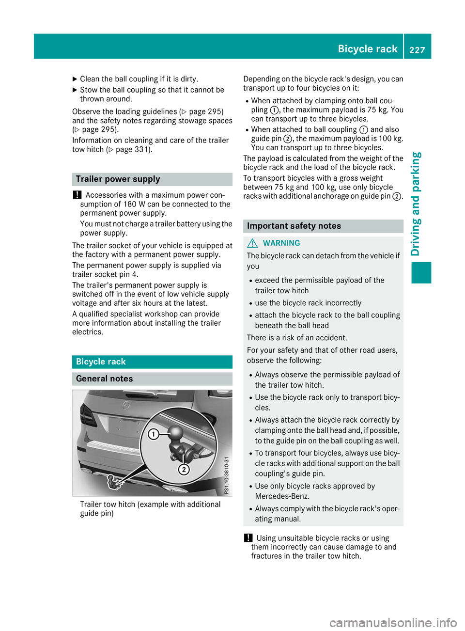
Trailer tow hitch (example with additional
guide pin) Depending on the bicycle rack's design, you can
transport up to four bicycles on it:
R When attached by clamping onto ball cou-
pling 0043, the maximum payload is 75 kg. You
can transport up to three bicycles.
R When attached to ball coupling 0043and also
guide pin 0044, the maximum payload is 100 kg.
You can transport up to three bicycles.
The payload is calculated from the weight of the
bicycle rack and the load of the bicycle rack.
To transport bicycles with a gross weight
between 75 kg and 100 kg, use only bicycle
racks with additional anchorage on guide pin 0044. Important safety notes
G
WARNING
The bicycle rack can detach from the vehicle if
you
R exceed the permissible payload of the
trailer tow hitch
R use the bicycle rack incorrectly
R attach the bicycle rack to the ball coupling
beneath the ball head
There is a risk of an accident.
For your safety and that of other road users,
observe the following:
R Always observe the permissible payload of
the trailer tow hitch.
R Use the bicycle rack only to transport bicy-
cles.
R Always attach the bicycle rack correctly by
clamping onto the ball head and, if possible, to the guide pin on the ball coupling as well.
R To transport four bicycles, always use bicy-
cle racks with additional support on the ball
coupling's guide pin.
R Use only bicycle racks approved by
Mercedes-Benz.
R Always comply with the bicycle rack's oper-
ating manual.
! Using unsuitable bicycle racks or using
them incorrectly can cause damage to and
fractures in the trailer tow hitch. Bicycle rack
227Driving and parking Z
Page 232 of 398
Important safety notes
G
WARNING
If you operate information systems and com-
munication equipment integrated in the vehi- cle when driving, you may be distracted from
the traffic situation. You could also lose con-
trol of the vehicle. There is a risk of an acci-
dent.
Only operate this equipment when the traffic
situation permits. If you are not sure that this
is possible, park the vehicle paying attention
to traffic conditions and operate the equip-
ment when the vehicle is stationary.
You must observe the legal requirements for the country in which you are currently driving whenoperating the on-board computer. G
WARNING
If the instrument cluster has failed or mal-
functioned, you may not recognize function
restrictions in systems relevant to safety. The operating safety of your vehicle may be
impaired. There is a risk of an accident.
Drive on carefully. Have the vehicle checked
at a qualified specialist workshop immedi-
ately.
If the operating safety of your vehicle is
impaired, pull over as soon as it is safe to do so.
Contact a qualified specialist workshop.
The on-board computer only shows messages or warnings from certain systems in the multifunc-tion display. You should therefore make sure
your vehicle is operating safely at all times.
For an overview, see the instrument panel illus-
tration (Y page 37). Displays and operation
Instrument cluster lighting
The lighting in the instrument cluster, in the dis-
plays and the controls in the vehicle interior can be adjusted using the brightness control knob.
The brightness control knob is located on the
bottom left of the instrument cluster
(Y page 37). X
Turn the brightness control knob clockwise or
counter-clockwise.
If you turn the light switch to 0058,0060or
0058, the brightness is dependent upon the
brightness of the ambient light.
i The light sensor in the instrument cluster
automatically controls the brightness of the
multifunction display.
In daylight, the displays in the instrument
cluster are not illuminated. Speedometer with segments
The segments in the speedometer indicate
which speed range is available.
R Cruise control activated (Y page 171):
The segments light up from the stored speed to the maximum speed.
R Active Distance Assist DISTRONIC activated
(Y page 172):
One or two segments in the set speed range
light up.
R Active Distance Assist DISTRONIC detects a
vehicle in front moving more slowly than the
stored speed:
The segments between the speed of the vehi- cle in front and the stored speed light up. Tachometer
! Do not drive in the overrevving range, as this
could damage the engine.
The red band in the tachometer indicates the
engine's overrevving range.
The fuel supply is interrupted to protect the
engine when the red band is reached. Outside temperature display
You should pay special attention to road condi-
tions when temperatures are around freezing
point.
Bear in mind that the outside temperature dis-
play indicates the temperature measured and
does not record the road temperature.
The outside temperature display is in the multi-
function display (Y page 232).230
Displays and operationOn-board computer and displays
Page 233 of 398
There is a short delay before a change in outside
temperature appears in the multifunction dis-
play. Coolant temperature gauge
G
WARNING
Opening the hood when the engine is over-
heated or when there is a fire in the engine
compartment could expose you to hot gases
or other service products. There is a risk of
injury.
Let an overheated engine cool down before
opening the hood. If there is a fire in the
engine compartment, keep the hood closed
and contact the fire department.
! If the coolant temperature is too high, a dis-
play message is shown.
If the coolant temperature display is in the
area marked in red, do not continue driving.
Otherwise, the engine will be damaged.
The coolant temperature gauge is in the instru-
ment cluster on the right-hand side (Y page 37).
Under normal operating conditions and with the specified coolant level, the coolant temperature gauge may rise to the red marking. Operating the on-board computer
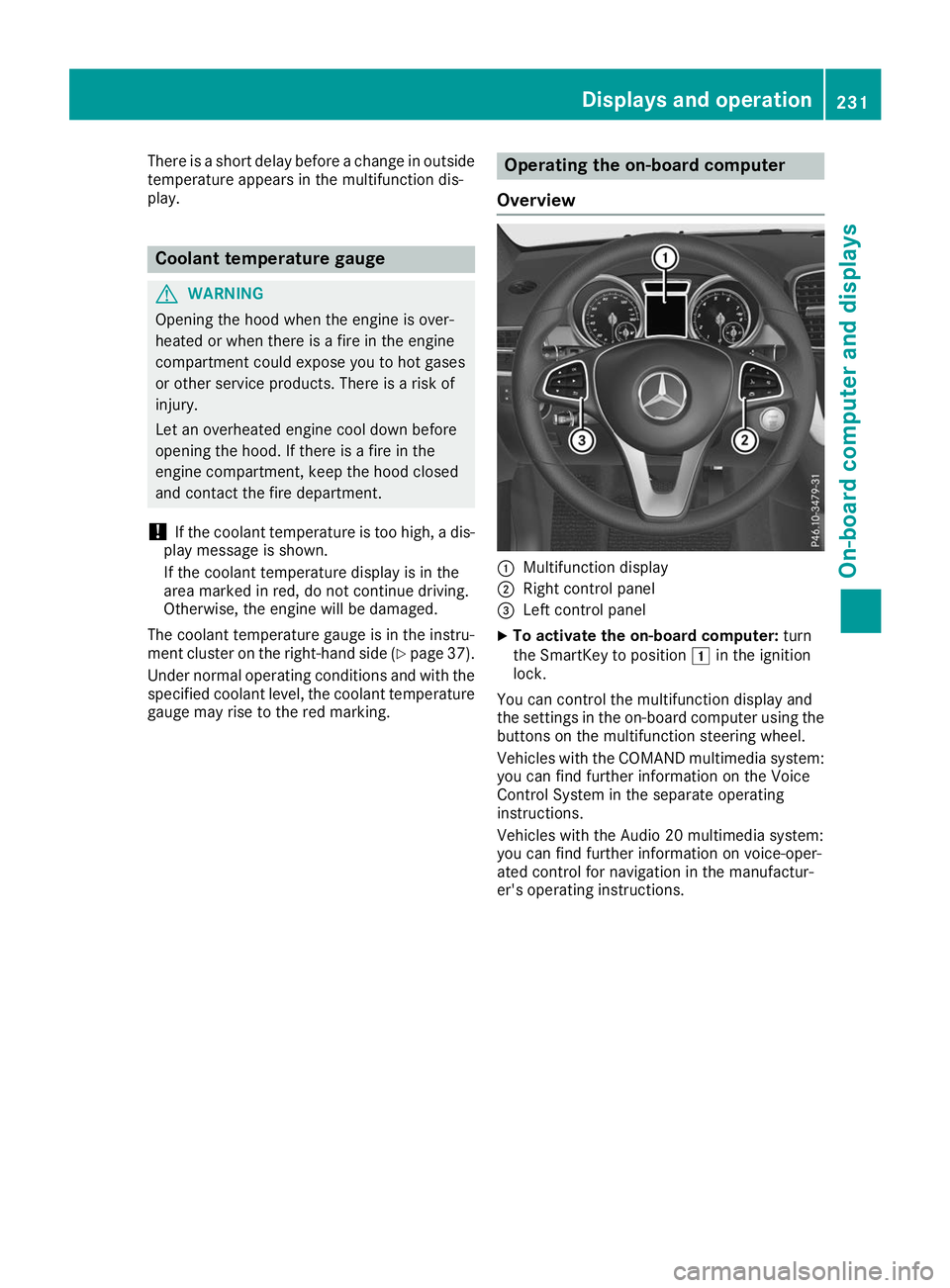
Overview 0043
Multifunction display
0044 Right control panel
0087 Left control panel
X To activate the on-board computer: turn
the SmartKey to position 0047in the ignition
lock.
You can control the multifunction display and
the settings in the on-board computer using the buttons on the multifunction steering wheel.
Vehicles with the COMAND multimedia system: you can find further information on the Voice
Control System in the separate operating
instructions.
Vehicles with the Audio 20 multimedia system:
you can find further information on voice-oper-
ated control for navigation in the manufactur-
er's operating instructions. Displays and operation
231On-board computer and displays Z
Page 239 of 398
Telephone menu
Introduction G
WARNING
If you operate information systems and com-
munication equipment integrated in the vehi- cle when driving, you may be distracted from
the traffic situation. You could also lose con-
trol of the vehicle. There is a risk of an acci-
dent.
Only operate this equipment when the traffic
situation permits. If you are not sure that this
is possible, park the vehicle paying attention
to traffic conditions and operate the equip-
ment when the vehicle is stationary.
When telephoning, you must observe the legal
requirements for the country in which you are
currently driving.
X Switch on the mobile phone (see the manu-
facturer’s operating instructions).
X Switch on the multimedia system (see the
Digital Operator's Manual)
X Establish a Bluetooth ®
connection to the mul-
timedia system (see the Digital Operator's
Manual).
X Press the 0059or0065 button on the steering
wheel to select the Tel Telmenu.
You will see one of the following display mes-
sages in the multifunction display:
R Phone READY Phone READY or the name of the network
provider: the mobile phone has found a net-
work and is ready to receive.
R Phone No Service
Phone No Service: there is no network
available or the mobile phone is searching for
a network.
Accepting a call If someone calls you when you are in the
Tel
Tel
menu, a display message appears in the multi-
function display.
You can accept a call at any time regardless of
the menu selected.
X Press the 0061button on the steering wheel
to accept an incoming call. Rejecting or ending a call You can end or reject a call even if you are not in
the Tel Tel menu.
X Press the 0076button on the steering wheel
to reject or end a call.
Selecting an entry from the phone book X
Press the 0059or0065 button on the steering
wheel to select the Tel
Telmenu.
X Press the 0063,0064or0076 button to
switch to the phone book.
X Authorize access to the phone book on the
phone.
X Press the 0063or0064 button to select the
desired name.
or
X To start rapid scrolling: press and hold the
0063 or0064 button for longer than one sec-
ond.
Rapid scrolling stops when you release the
button or reach the end of the list.
X If only one telephone number is stored for
a name: press the 0061or0076 button to
start dialing.
or X If there is more than one number for a
particular name:
press the0061or0076
button to display the numbers.
X Press the 0063or0064 button to select the
number you want to dial.
X Press the 0061or0076 button to start dialing.
or
X To exit the telephone book: press the0076
or 0038 button.
Redialing The on-board computer saves the last names or
numbers dialed in the redial memory.
X Press the 0059or0065 button on the steering
wheel to select the Tel Telmenu.
X Press the 0061button to switch to the redial
memory.
X Press the 0063or0064 button to select the
desired name or number. Menus and submenus
237On-board computer and displays Z
Page 241 of 398
Further information about Active Distance
Assist DISTRONIC with Active Steering Assist
(Y page 179).
Activating/deactivating Active Brake
Assist You can use these functions to activate/deac-
tivate Active Brake Assist or, on vehicles with
the Driving Assistance package, to activate or
deactivate Active Brake Assist with cross-traffic
function.
X Press the 0059or0065 button on the steering
wheel to select the DriveAssist DriveAssistmenu.
X Press the 0063or0064 button to select
Brake Assist
Brake Assist.
X Press 0076to confirm.
The current selection appears.
X To activate/deactivate: press the0076but-
ton again.
When Active Brake Assist or Active Brake
Assist with cross-traffic function is deactiva-
ted, the 00D4symbol appears in the multi-
function display in the assistance graphic dis-
play.
Further information on Active Brake Assist
(Y page 67 )and Active Brake Assist with cross-
traffic function (Y page 72).
Activating/deactivating ATTENTION
ASSIST X
Press the 0059or0065 button on the steering
wheel to select the DriveAssist
DriveAssist menu.
X Press the 0063or0064 button to select
Attention Assist Attention Assist .
X Press the 0076button.
The current selection appears.
X Press 0076to confirm.
X Press the 0064or0063 button to set Off
Off,
Standard
Standard orSensitive
Sensitive .
X Press the 0076button to save the setting.
When ATTENTION ASSIST is deactivated, the
00D7 symbol appears in the multifunction dis-
play in the assistance graphics display.
For further information about ATTENTION
ASSIST, see (Y page 204). Activating/deactivating Blind Spot
Assist X
Press the 0059or0065 button on the steering
wheel to select the DriveAssist DriveAssistmenu.
X Press the 0063or0064 button to select
Blind Spot Assist
Blind Spot Assist .
X Confirm by pressing 0076on the steering
wheel.
The current selection appears.
X To activate/deactivate: press the0076but-
ton again.
For further information about Blind Spot Assist, see (Y page 207).
For further information about Active Blind Spot
Assist, see (Y page 210).
Activating/deactivating Lane Keeping
Assist X
Press the 0059or0065 button on the steering
wheel to select the DriveAssist DriveAssistmenu.
X Press the 0063or0064 button to select
Lane Keeping Assist
Lane Keeping Assist .
X Press 0076to confirm.
The current selection appears.
X Press 0076to confirm.
X Press the 0064or0063 button to set Off
Off,
Standard
Standard orAdaptive
Adaptive.
When Lane Keeping Assist or Active Lane
Keeping Assist is activated, the multifunction display shows the lane markings as bright
lines in the assistance graphic.
X Press the 0076button to save the setting.
For further information about Lane Keeping
Assist, see (Y page 208).
For further information about Active Lane Keep- ing Assist, see (Y page 212). Service menu
Depending on the equipment installed in the
vehicle, you have the following options in the
Serv. Serv. menu:
R calling up display messages in message mem-
ory (Y page 245)
R restarting the tire pressure loss warning sys-
tem (Y page 359) or checking the tire pres-
sure electronically (Y page 361)
R calling up the service due date (Y page 325). Menus and submenus
239On-board computer and displays Z
Page 243 of 398
R
Highway mode
R Active light function
R Cornering light function
R Extended range fog lamps
R Off-road lights
Further information on the Intelligent Light Sys-
tem (Y page 117).
Vehicle submenu Activating/deactivating the automatic
door locking mechanism
If you activate the Automatic AutomaticDoor
Door Lock
Lockfunc-
tion, the vehicle is centrally locked above a
speed of approximately 9 mph (15 km/h).
X Press the 0059or0065 button on the steering
wheel to select the Sett.
Sett. menu.
X Press the 0064or0063 button to select the
Vehicle
Vehicle submenu.
X Press 0076to confirm.
X Press the 0064or0063 button to select the
Automatic Door Lock Automatic Door Lock function.
When the Automatic Door Lock
Automatic Door Lock function is
activated, the vehicle doors are displayed in
orange in the multifunction display.
X Press the 0076button to save the setting.
For further information on the automatic locking
feature, see (Y page 84).
Activating/deactivating the acoustic
locking verification signal If you switch on the Acoustic
Acoustic Lock Lockfunction, an
acoustic signal sounds when you lock the vehi-
cle.
X Press the 0059or0065 button on the steering
wheel to select the Settings
Settings menu.
X Press the 0064or0063 button to select the
Vehicle
Vehicle submenu.
X Press 0076to confirm.
X Press the 0064or0063 button to select the
Acoustic Lock
Acoustic Lock function.
If the Acoustic Lock
Acoustic Lock function is activated,
the 0037 symbol in the multifunction display
lights up orange.
X Press the 0076button to save the setting. Convenience submenu Activating/deactivating the EASY-
ENTRY/EXIT feature
G
WARNING
When the EASY-ENTRY/EXIT feature adjusts
the steering wheel, you and other vehicle
occupants – particularly children – could
become trapped. There is a risk of injury.
While the EASY-ENTRY/EXIT feature is mak-
ing adjustments, make sure that no one has
any body parts in the sweep of the steering
wheel.
If somebody becomes trapped:
R press one of the memory function position
buttons, or
R move the switch for steering wheel adjust-
ment in the opposite direction to that in
which the steering wheel is moving.
The adjustment process is stopped.
X Press the 0059or0065 button on the steering
wheel to select the Sett. Sett.menu.
X Press the 0064or0063 button to select the
Convenience
Convenience submenu.
X Press 0076to confirm.
X Using 0064or0063, select the Easy
EasyEntry/
Entry/
Exit
Exit function.
If the Easy
Easy Entry/Exit
Entry/Exit function is activated,
the vehicle steering wheel is displayed in
orange in the multifunction display.
X Press the 0076button to save the setting.
Further information on the EASY-ENTRY/EXIT
feature (Y page 109).
Switching the seat belt adjustment on/off X Press the 0059or0065 button on the steering
wheel to select the Settings
Settings menu.
X Press the 0064or0063 button to select the
Convenience Convenience submenu.
X Press 0076to confirm.
X Press the 0064or0063 button to select the
Belt Adjustment
Belt Adjustment function.
If the Belt
Belt Adjustment
Adjustment function is activated,
the vehicle seat belt is shown in orange in the multifunction display.
X Press the 0076button to save the setting. Menus and submenus
241On-board computer and displays Z