Page 82 of 681

#
Todeactivate: pressthe& button on the
ke y twice in quick succession.
The battery check lamp of theke yflashes
twice brief lyand lights up once. #
Toactivate: press any button on thekey.
% When theve hicle is star ted with theke y in
th estow age compartment of the cent recon‐
sole, theke y functions are automatical ly
activated (→ page180). Re
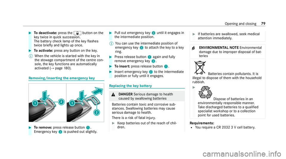
moving/inserting the eme rgency key #
Toremo ve:press release button 1.
Emer gency key2 is pushed out slight ly. #
Pull out emer gency key2 until it en gage s in
th e intermediate position.
% You can use the intermediate position of
emer gency key2 toattach theke yto akey
ri ng. #
Press release button 1again and fully
re mo veemer gency key2. #
Toinser t:press release button 1. #
Insert emer gency key2 tothe intermediate
position or fully until it engages. Re
placing the key battery &
DANG ER Serious damage tohealth
caused byswallowing batteries
Batteries contain toxic and cor rosive sub‐
st ances. Swallowing bat teries may cause
serious damage tohealth.
There is a risk of fata l injur y. #
Keep batteries out of there ach of chil‐
dren. #
If batteries are swallo wed, seek medical
attention immediately. +
ENVIRONMEN
TALNO TEEnvironmental
dama gedue toimproper disposal of bat‐
te ries Batteries conta
in pollutants. It is
illegal todispose of them with the household
ru bbish. #
Dispose of batteries in an
environmen tally responsible manner.
Ta ke dischar ged batteries toaqu alified
specialist workshop or toa collection
point for used batteries. Re
quirements:
R Yourequ ire a CR 2032 3 V cell batter y. Opening and closing
79
Page 111 of 681
Ad
justing the front passen ger seat electri‐
cally from the driver's seat Re
quirement:
R The po wer supp lyhas been switched on
(→ page 178). Yo
u can call up thefo llowing functions forthe
front passenger sea t:
R seat adjustment R
seat heater
R seat ventilation
R memory function #
Toselect the front passenger seat: press
button 1.
When the indicator lamp lights up, the front
passenger seat is selected. #
Adjust the front passenger seat using the
buttons on the door control panel on the
driver's side. #
Select the driver's seat: Pressthe1 but‐
to n again.
When the indicator lamp goes out, the driv‐
er's seat has been selected. Ad
justing the 4-w aylumbar support 1
Raise
2 Soften
3 Lower
4 Harden #
Using buttons 1to4 , adjust the conto ur
of the backrest individually tosuit your bac k. 108
Seats and stowing
Page 122 of 681
#
Push release le ver1 down as far as it will
go.
The steering column is unloc ked. #
Adjust height 2and di stance 3tothe
st eering wheel. #
Push release le ver1 up as far as it will go.
The steering column is loc ked. #
Check and make sure that thesteering col‐
umn is loc kedby moving thesteering wheel. Ad
justing the steering wheel electrically The
steering wheel can be adjus ted when the
ignition is switched off. 1
Adjusts the dis tance tothesteering wheel
2 Adjusts the height #
Save the settings with the memory function
(→ page 121). Switching
thest eering wheel heater on/off R
the ignition is switched on. #
Toswitch on: pushthe switch toposition
1.
The indicator lamp 3lights up. #
Toswitch off: pushthe switch toposition
2.
The indicator lamp 3goes out. Seats and
stowing 11 9
Page 142 of 681
#
Ensu rethat no children can access the
cup holder's hot heating elements. #
Never lea vechildren unat tended in the
ve hicle. *
NO
TE If
yo u place objects into thete mp erature-
controlled cup holder, they may become
dama ged. #
Do not place objects into thete mp era‐
ture-contro lled cup holder. 1
Cup holder in the front cent reconsole 1
Cup holder in there ar #
Toswitch on: on cup holder 1, press but‐
to n2 repeatedly until the blue (keep cool)
or red (keep warm) indicator lamp on the but‐
to n lights up.
If yo u use the heating function, the me tal
inse rtof the cup holder is heated. Once a
cer tain temp erature has been reached, the
wa rning lamp lights up. Do not reach into the Seats and
stowing 13 9
Page 145 of 681
&
DANG ER Risk of fata l injury due toincor‐
re ct handling of the soc ket
Yo u could recei vean electric shock:
R ifyo ure ach into the soc ket.
R ifyo u insert unsuitable devices or objects
into the soc ket. #
Only connect suitable devices tothe
soc ket. Re
quirements:
R Only connect devices with a suitable plug
which con form sto thest andards specific to
th e count ryyou are in.
R Only connect devices uptoa maximum of
15 0wa tts (0.65 A).
R Do not use multiple soc ket outlets. Example: 230 V soc
ket in the cent reconsole #
Open flap 3. #
Insert the plug of the device into 230 V
soc ket1.
When the on-board electrical sy stem voltage
is suf ficient, indicator la mp2lights up. Using
the12 V so cket inthe load compa rt‐
ment Re
quirements:
R Only devices with up toa maximum of
24 0wa tts (20 A) are pe rmissible. #
Lift up cap 1ofthe soc ket and insert the
plug of the device. 14 2
Seats and stowing
Page 150 of 681

Exterior lighting
Note
s onchanging the lights when driving
abroad Ve
hicles with static LED headlamps: it is not
necessary tochange the headlamps. The legal
re qu irements are also met in countries in which
traf fic drives on theot her side of thero ad.
Ve hicles with Intelligent Light Sy stem: the head‐
lamps are automatically switched over when the
ve hicle enters countries where traf fic drives on
th eot her side of thero ad. If necessar y,the
headlamp s can also be switched over manually .
In thefo llowing cases, check the setting of the
headlamp s, andchange it manually if necessary:
R Ifth eDipped-beam setting (left/right-side
traffic) Manual adjustment only message is
displa yed.
R Ifth eCheck dipped-beam setting (left/right-
side traffic) message is displa yed.
Once the headlamps ha vebeen changed:
R oncoming traf fic will not be dazzled R
the edge of thero ad will not be illuminated
as far or as high
R the "mo torw ay mode" and "enhanced fog
light" functions will not be available Information about lighting sy
stems and your
re sponsibility The
various lighting sy stems of theve hicle are
only aids. The driver of theve hicle is responsible
fo r cor rect vehicle illumination in accordance
with the pr evailing light and visibility conditions,
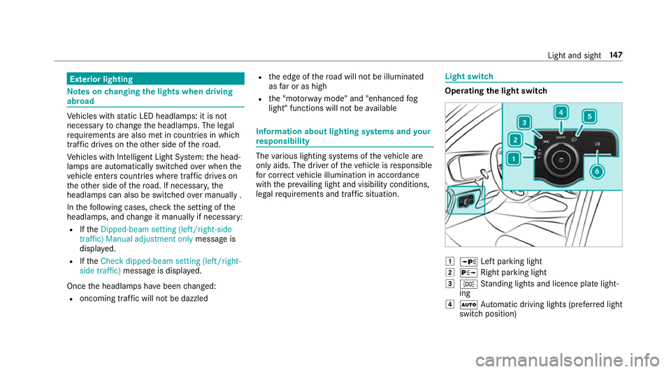
legal requ irements and traf fic situation. Light switch
Ope
rating the light switch 1
W Left pa rking light
2 X Right parking light
3 T Standing lights and licence plate light‐
ing
4 Ã Automatic driving lights (prefer red light
switch position) Light and sight
147
Page 151 of 681

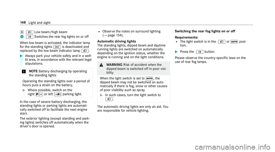
5
L Low beam/high beam
6 R Switches there ar fog lights on or off
When low beam is activated, the indicator lamp
fo rth est anding lights Tis deactivated and
re placed bythe low beam indicator lamp L.#
Alw ays park your vehicle safely and in a well-
lit area, in accordance with there leva nt le gal
st ipulations.
* NO
TEBattery discharging byoperating
th est anding lights Operating
thest anding lights over a period of
hours puts a stra in on the batter y. #
Where possible, switch on the
ri ght X or left Wparking light. In
the case of se vere battery discharging, the
st anding lights or parking lights are automati‐
cally swit ched off tofacilitate the next engine
st art.
The exterior lighting (e xcept standing and park‐
ing lights) swit ches off automatically when the
driver's door is opened. R
Obser vethe no tes on sur round lighting
(→ page 154).
Au tomatic driving lights
The standing lights, dipped beam and daytime
ru nning lights are switched on au tomatical ly
depending on the ignition status, whe ther the
engine is running and on the light conditions. &
WARNING Risk of accident when the
dipped beam is switched off in poor visi‐
bility
When the light switch is set toà ,the
dipped beam may not be switched on auto‐
matically if there is fog, snow or other causes
of poor visibility such as spr ay. #
In such cases, turn the light switch to
L . The automatic driving lights are only an aid.
Yo u
are responsible forve hicle lighting. Switching
there ar fog lights on or off
Re quirements:
R The light switch is in the L orà posi‐
tion. #
Press the R button.
Please obser vethe count ry-specific la wsonthe
use of rear fog lamps. 14 8
Light and sight
Page 152 of 681

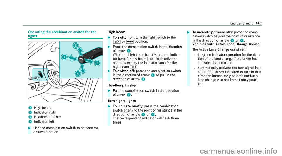
Operating
the combination switch for the
lights 1
High beam
2 Indicator, right
3 Headlamp flasher
4 Indicator, left #
Use the combination switch toactivate the
desired function. High beam #
Toswitch on: turnthe light switch tothe
L orà position. #
Press the combination switch in the direction
of ar row1.
When the high beam is activated, the indica‐
to r lamp for low beam Lis deactivated
and replaced bythe indicator lamp forthe
high beam K. #
Toswitch off: pressthe combination switch
in the direction of ar row1or pull in the
direction of ar row3.
Headlamp flasher #
Pull the combination switch in the direction
of ar row3.
Tu rn signal lights #
Toindicate briefl y:press the combination
switch briefly tothe point of resis tance in the
direction of ar row2or4.
The cor responding indicator will flash three
times. #
Toindicate permanentl y:press the combi‐
nation switch be yond the point of resis tance
in the direction of ar row2or4.
Ve hicles with Active Lane Change Assi st
The Active Lane Change Assi stcan:
R lengthen indicator ope ration forth e dura‐
tion of the lane change if the driver has
activated the indicator.
R automatically activate the turn signal indi‐
cator if the driver indicated toturn in that
direction immediately beforehand but a
lane change was not immediately possi‐
ble. Light and sight
14 9