2019 MERCEDES-BENZ GLE COUPE tailgate
[x] Cancel search: tailgatePage 204 of 370
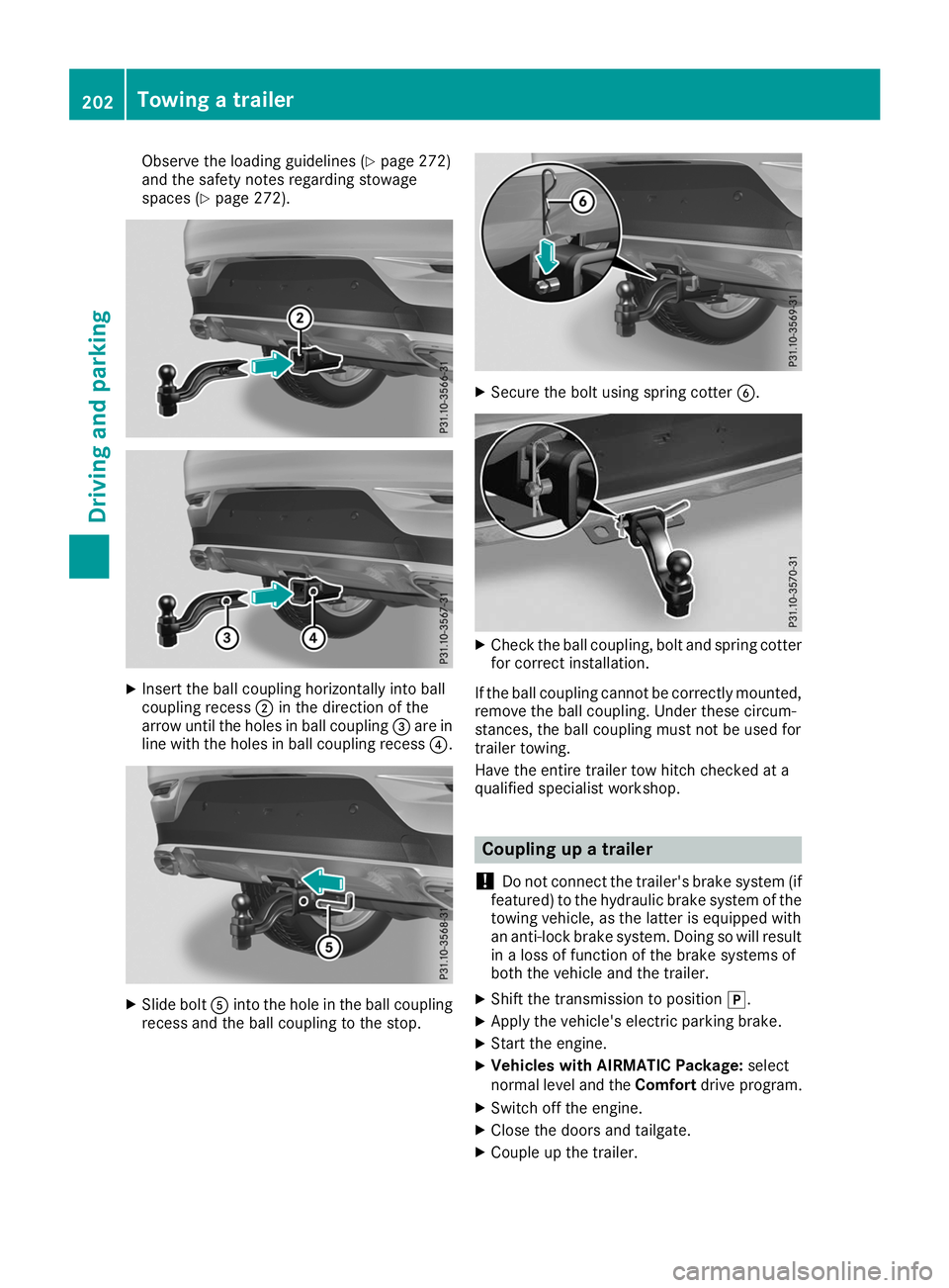
Observe the loading guidelines (Y
page 272)
and the safety notes regarding stowage
spaces (Y page 272). X
Insert the ball coupling horizontally into ball
coupling recess 0044in the direction of the
arrow until the holes in ball coupling 0087are in
line with the holes in ball coupling recess 0085.X
Slide bolt 0083into the hole in the ball coupling
recess and the ball coupling to the stop. X
Secure the bolt using spring cotter 0084. X
Check the ball coupling, bolt and spring cotter
for correct installation.
If the ball coupling cannot be correctly mounted,
remove the ball coupling. Under these circum-
stances, the ball coupling must not be used for
trailer towing.
Have the entire trailer tow hitch checked at a
qualified specialist workshop. Coupling up a trailer
! Do not connect the trailer's brake system (if
featured) to the hydraulic brake system of the towing vehicle, as the latter is equipped with
an anti-lock brake system. Doing so will result
in a loss of function of the brake systems of
both the vehicle and the trailer.
X Shift the transmission to position 005D.
X Apply the vehicle's electric parking brake.
X Start the engine.
X Vehicles with AIRMATIC Package: select
normal level and the Comfortdrive program.
X Switch off the engine.
X Close the doors and tailgate.
X Couple up the trailer. 202
Towing a trailerDriving and parking
Page 206 of 370
R
If possible, do not brake suddenly, but instead
depress the brake pedal moderately at first sothat the trailer can activate its brakes. Then
increase the pressure on the brake pedal.
R If the automatic transmission repeatedly
shifts between gears on uphill or downhill gra- dients, shift to a lower gear using the left-hand
steering wheel paddle shifter.
A lower gear and lower speed reduce the risk of engine failure.
R When driving downhill, shift to a lower gear to
utilize the engine's braking effect.
Avoid continuous brake application as this
may overheat the vehicle brakes and, if instal-
led, the trailer brakes.
R If the coolant temperature increases dramat-
ically while the air-conditioning system is
switched on, switch off the air-conditioning
system.
Coolant heat can also be dissipated by open-
ing the windows and switching the ventilation blower and the interior temperature to the
highest level.
R When overtaking, pay particular attention to
the extended length of your vehicle/trailer
combination.
Due to the length of the vehicle/trailer com-
bination, you require additional road space in relation to the vehicle you are overtaking
before you can change back to the original
lane. Decoupling a trailer
G
WARNING
If you uncouple a trailer with the overrun
brake engaged, you could trap your hand
between the vehicle and the trailer drawbar.
There is a risk of injury.
Do not uncouple a trailer if the overrun brake is engaged. G
WARNING
Vehicles with level control:
The vehicle is lowered as soon as you discon-
nect the trailer cable. This could result in your limbs or those of other people that are
between the vehicle body and tires or under- neath the vehicle being trapped. There is a
risk of injury.
Make sure that nobody is in the immediate
vicinity of the wheel housings or under the
vehicle when you disconnect the trailer cable.
! Do not disconnect a trailer with an engaged
overrun brake. Otherwise, your vehicle could
be damaged by the rebounding of the overrun brake.
X Shift the transmission to position 005D.
X Apply the vehicle's electric parking brake.
X Start the engine.
X Close the doors and tailgate.
X Apply the trailer's parking brake.
X Detach the trailer cable and decouple the
trailer.
X Switch off the engine. Permissible trailer loads and drawbar
loads
Weight specifications Maximum allowable gross mass
The gross vehicle weight of the trailer is calcu-
lated by adding the weight of the trailer to the
weight of the load and equipment on the trailer.
You will find installing dimensions and loads
under "Technical data" (Y page 367).
Permissible noseweight You will find installing dimensions and loads
under "Technical data" (Y page 367).
Loading a trailer R
When loading the trailer, make sure that nei-
ther the permissible gross weight of the trailer
nor the gross vehicle weight are exceeded.
The permissible gross vehicle weight is indi-
cated on the identification plate located on
the B-pillar on the driver's side of the vehicle.
You can find the maximum permissible values
on the type plates of your vehicle and the
trailer. When calculating how much weight 204
Towing a trailerDriving and parking
Page 250 of 370
Display messages
Possible causes/consequences and
0050
0050Solutions Service
Service
Required
Required Do
Do
Not Shift Gears
Not Shift Gears
Visit Dealer Visit Dealer You cannot change the transmission position due to a malfunction.
A warning tone also sounds.
If transmission position
005Bis selected:
X Drive to a qualified specialist workshop without shifting the trans-
mission from position 005B.
If position 005E,005Cor005D is selected:
X Secure the vehicle against rolling away (Y page 144).
X Notify a qualified specialist workshop or breakdown service. Reversing Reversing
Not
NotPossi‐
Possi‐
ble
ble Service
Service Required
Required You can no longer shift to transmission position
005Edue to a malfunc-
tion.
Transmission positions 005D,005Cor005B continue to be available.
A warning tone also sounds.
X Visit a qualified specialist workshop. Transmission Mal‐ Transmission Mal‐
function Stop function Stop A malfunction has occurred in the mechanical transmission compo-
nents.
A warning tone also sounds. The transmission shifts automatically to position 005C.
X Pull over and stop the vehicle safely as soon as possible, paying
attention to road and traffic conditions.
X Shift the transmission to position 005D.
X Secure the vehicle against rolling away (Y page 144).
X Notify a qualified specialist workshop or breakdown service. Auxiliary Battery Auxiliary Battery
Malfunction Malfunction The auxiliary battery for the automatic transmission is no longer being
charged.
X Visit a qualified specialist workshop.
X Until then, always set the automatic transmission to position 005D
before switching off the engine.
X Before leaving the vehicle, apply the electric parking brake. 0065 The tailgate is open
G WARNING
When the engine is running, exhaust gases can enter the vehicle inte- rior if the tailgate is open.
There is a risk of poisoning.
X Close the tailgate. 248
Display
messagesOn-board computer and displays
Page 274 of 370
Stowage areas
Loading guidelines
G
WARNING
If objects, luggage or loads are not secured or not secured sufficiently, they could slip, tip
over or be flung around and thereby hit vehicle
occupants. There is a risk of injury, particu-
larly in the event of sudden braking or a sud-
den change in direction.
Always store objects so that they cannot be
flung around. Secure objects, luggage or
loads against slipping or tipping before the
journey. G
DANGER
Combustion engines emit poisonous exhaust
gases such as carbon monoxide. Exhaust
gases can enter the vehicle interior if the tail- gate is open while the engine is running, espe-cially if the vehicle is in motion. There is a risk of poisoning.
Always switch off the engine before opening
the tailgate. Never drive with the tailgate
open. G
WARNING
The exhaust tail pipe and tail pipe trim can
become very hot. If you come into contact
with these parts of the vehicle, you could burn
yourself. There is a risk of burns.
Always be particularly careful and supervise
children closely around the exhaust pipe and
the exhaust pipe trims. Allow these compo-
nents to cool down before touching them.
The gross vehicle weight (GVW) is the vehicle
weight including fuel, vehicle tool kit, spare
wheel, installed accessories, vehicle occupants and luggage/cargo.
Do not exceed the load limit or permitted grossvehicle weight rating (GVWR) for your vehicle.
The gross load limit and the GVWR are specified
on the vehicle identification plate on the B-pillar
of the driver's door (Y page 337).
The load must also be distributed so that the
weight on each axle never exceeds the gross
axle weight rating (GAWR) for the front and rear axles. The specifications for GVWR and GAWR
are on the vehicle identification plate on the B-
pillar of the driver's door (Y
page 337).
Observe the notes on loading the vehicle
(Y page 337).
The handling characteristics of a laden vehicle
are dependent on the distribution of the load
within the vehicle. For this reason, you should
observe the following notes when transporting a
load:
R Never exceed the maximum permissible
gross vehicle mass or the gross axle weight
rating for the vehicle (including occupants).
R The cargo compartment is the preferred place
to carry objects.
R Position heavy loads as far forward as possi-
ble and as low down in the cargo compart-
ment as possible.
R The load must not protrude above the upper
edge of the seat backrests.
R Always place the load against the rear or front
seat backrests. Make sure that the seat
backrests are securely locked into place.
R Always place the load behind unoccupied
seats if possible.
R Use the cargo tie-down rings and the parcel
nets to transport loads and luggage.
R Use cargo tie-down rings and fastening mate-
rials appropriate for the weight and size of the load.
R Secure the load with sufficiently strong and
wear-resistant tie-downs. Pad sharp edges for
protection. Stowage spaces
Important safety notes G
WARNING
If you transport objects in the vehicle interior and these are not adequately secured, they
could slip or be flung around and thereby
strike vehicle occupants. In addition, cup
holders, open stowage spaces and mobile
phone brackets may not always be able to
hold the objects placed in them in the event of an accident. There is a risk of injury, particu-
larly in the event of sharp braking or sudden
changes of direction. 272
Stowage areasStowage and features
Page 280 of 370
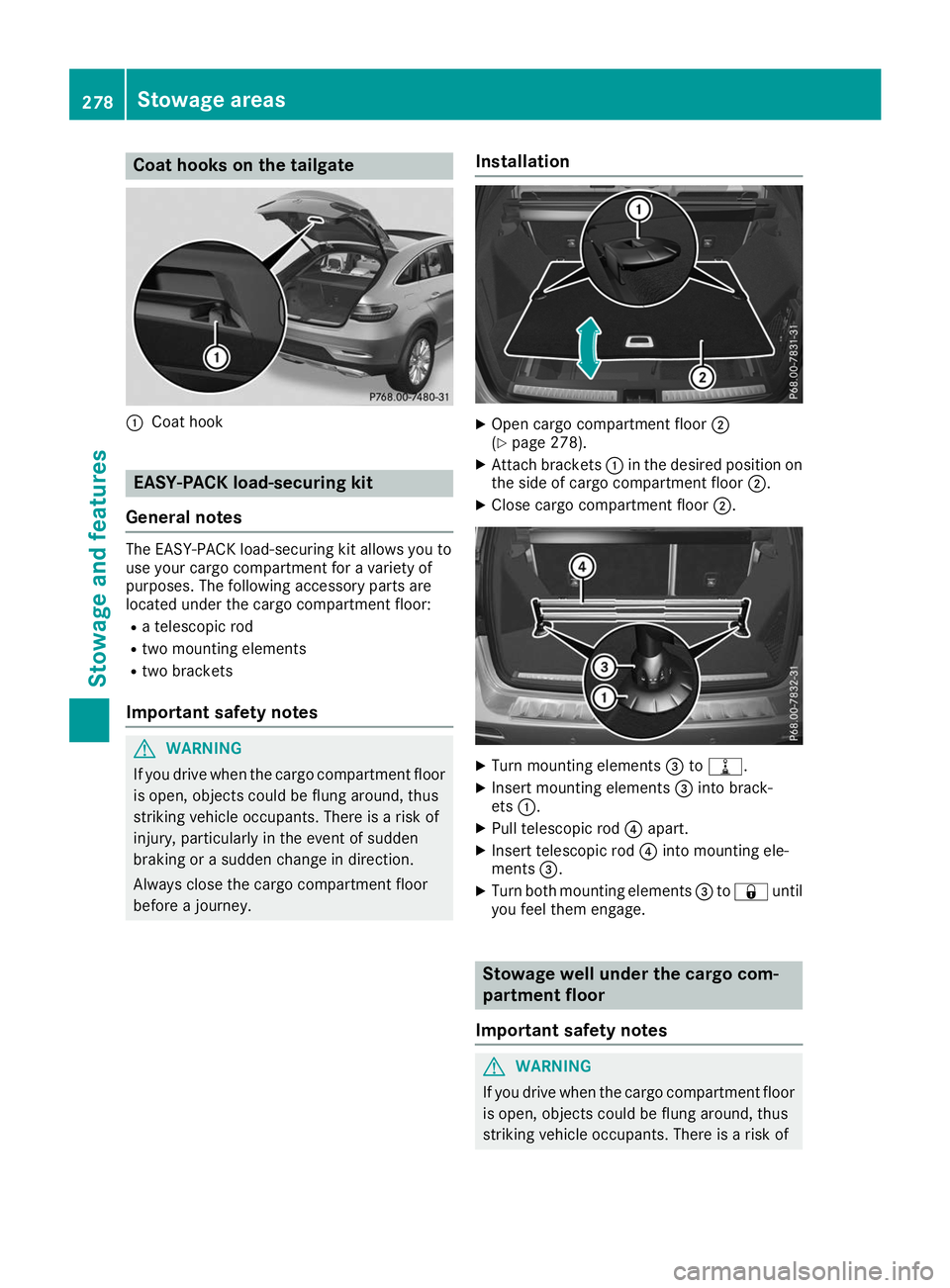
Coat hooks on the tailgate
0043
Coat hook EASY-PACK load-securing kit
General notes The EASY-PACK load-securing kit allows you to
use your cargo compartment for a variety of
purposes. The following accessory parts are
located under the cargo compartment floor:
R a telescopic rod
R two mounting elements
R two brackets
Important safety notes G
WARNING
If you drive when the cargo compartment floor is open, objects could be flung around, thus
striking vehicle occupants. There is a risk of
injury, particularly in the event of sudden
braking or a sudden change in direction.
Always close the cargo compartment floor
before a journey. Installation X
Open cargo compartment floor 0044
(Y page 278).
X Attach brackets 0043in the desired position on
the side of cargo compartment floor 0044.
X Close cargo compartment floor 0044. X
Turn mounting elements 0087to006E.
X Insert mounting elements 0087into brack-
ets 0043.
X Pull telescopic rod 0085apart.
X Insert telescopic rod 0085into mounting ele-
ments 0087.
X Turn both mounting elements 0087to0037 until
you feel them engage. Stowage well under the cargo com-
partment floor
Important safety notes G
WARNING
If you drive when the cargo compartment floor is open, objects could be flung around, thus
striking vehicle occupants. There is a risk of 278
Stowage areasStowage and features
Page 282 of 370
change. The vehicle tilts more severely when
cornering and may react more sluggishly to
steering input.
If you exceed the maximum roof load, the
driving characteristics, as well as the steering and braking, will be greatly impaired. There is
a risk of an accident.
Adjust your driving style and never exceed the
maximum roof load.
! Mercedes-Benz recommends that you only
use roof carriers that have been tested and
approved for Mercedes-Benz vehicles. This
helps to prevent damage to the vehicle.
Position the load on the roof carrier in such a
way that the vehicle will not sustain damage
even when it is in motion.
Depending on the vehicle equipment, ensure
that when the roof carrier is installed you can:
R raise the sliding sunroof fully
R open the panorama roof with power tilt/
sliding panel fully
R open the tailgate fully
You will find information on the maximum roof
load in the "Technical data" section
(Y page 364).
An incorrectly secured roof carrier or roof load
may become detached from the vehicle. You
must therefore ensure that you observe the roof
carrier manufacturer's installation instructions.
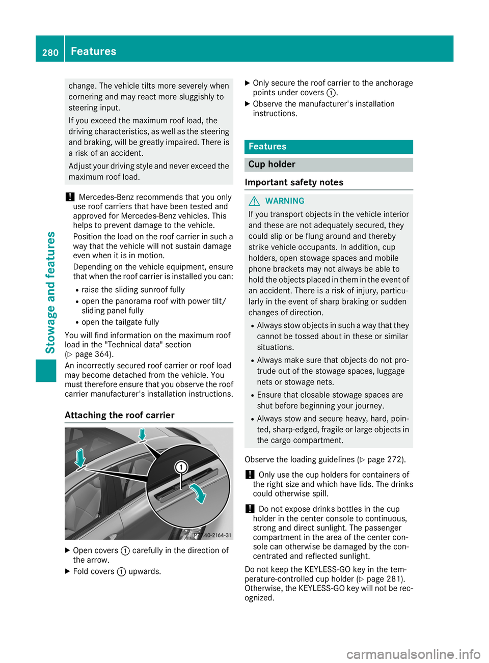
Attaching the roof carrier X
Open covers 0043carefully in the direction of
the arrow.
X Fold covers 0043upwards. X
Only secure the roof carrier to the anchorage
points under covers 0043.
X Observe the manufacturer's installation
instructions. Features
Cup holder
Important safety notes G
WARNING
If you transport objects in the vehicle interior and these are not adequately secured, they
could slip or be flung around and thereby
strike vehicle occupants. In addition, cup
holders, open stowage spaces and mobile
phone brackets may not always be able to
hold the objects placed in them in the event of an accident. There is a risk of injury, particu-
larly in the event of sharp braking or sudden
changes of direction.
R Always stow objects in such a way that they
cannot be tossed about in these or similar
situations.
R Always make sure that objects do not pro-
trude out of the stowage spaces, luggage
nets or stowage nets.
R Ensure that closable stowage spaces are
shut before beginning your journey.
R Always stow and secure heavy, hard, poin-
ted, sharp-edged, fragile or large objects in
the cargo compartment.
Observe the loading guidelines (Y page 272).
! Only use the cup holders for containers of
the right size and which have lids. The drinks
could otherwise spill.
! Do not expose drinks bottles in the cup
holder in the center console to continuous,
strong and direct sunlight. The passenger
compartment in the area of the center con-
sole can otherwise be damaged by the con-
centrated and reflected sunlight.
Do not keep the KEYLESS-GO key in the tem-
perature-controlled cup holder (Y page 281).
Otherwise, the KEYLESS-GO key will not be rec-
ognized. 280
FeaturesStowage and features
Page 312 of 370
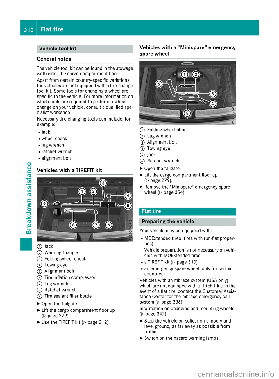
Vehicle tool kit
General notes The vehicle tool kit can be found in the stowage
well under the cargo compartment floor.
Apart from certain country-specific variations,
the vehicles are not equipped with a tire-change
tool kit. Some tools for changing a wheel are
specific to the vehicle. For more information on
which tools are required to perform a wheel
change on your vehicle, consult a qualified spe-
cialist workshop.
Necessary tire-changing tools can include, for
example:
R jack
R wheel chock
R lug wrench
R ratchet wrench
R alignment bolt
Vehicles with a TIREFIT kit 0043
Jack
0044 Warning triangle
0087 Folding wheel chock
0085 Towing eye
0083 Alignment bolt
0084 Tire inflation compressor
006B Lug wrench
006C Ratchet wrench
006D Tire sealant filler bottle
X Open the tailgate.
X Lift the cargo compartment floor up
(Y page 279).
X Use the TIREFIT kit (Y page 312). Vehicles with a "Minispare" emergency
spare wheel 0043
Folding wheel chock
0044 Lug wrench
0087 Alignment bolt
0085 Towing eye
0083 Jack
0084 Ratchet wrench
X Open the tailgate.
X Lift the cargo compartment floor up
(Y page 279).
X Remove the "Minispare" emergency spare
wheel (Y page 354). Flat tire
Preparing the vehicle
Your vehicle may be equipped with: R MOExtended tires (tires with run-flat proper-
ties)
Vehicle preparation is not necessary on vehi-
cles with MOExtended tires.
R a TIREFIT kit (Y page 310)
R an emergency spare wheel (only for certain
countries)
Vehicles with an mbrace system (USA only)
which are not equipped with a TIREFIT kit: in the event of a flat tire, contact the Customer Assis-tance Center for the mbrace emergency call
system (Y page 286).
Information on changing and mounting wheels
(Y page 347).
X Stop the vehicle on solid, non-slippery and
level ground, as far away as possible from
traffic.
X Switch on the hazard warning lamps. 310
Flat tireBreakdo
wn assis tance
Page 352 of 370

R
Never open or close a door or the tailgate
when the vehicle is raised.
R Make sure that no persons are present in the
vehicle when the vehicle is raised. X
Using lug wrench 0043, loosen the bolts on the
wheel you wish to change by about one full
turn. Do not unscrew the bolts completely. The jacking points are located just behind the
front wheel housings and just in front of the rear wheel housings (arrows).
X Take the ratchet wrench out of the vehicle
tool kit and place it on the hexagon nut of the
jack so that the letters AUFare visible. X
Position jack 0087at jacking point 0044. X
Make sure the foot of the jack is directly
beneath the jacking point.
X Turn ratchet wrench 0085until jack 0087sits
completely on jacking point 0044and the base
of the jack lies evenly on the ground.
X Turn ratchet wrench 0085until the tire is raised
a maximum of 1.2 in (3 cm) from the ground.
Removing a wheel !
Do not place wheel bolts in sand or on a dirty
surface. The bolt and wheel hub threads could
otherwise be damaged when you screw them
in.
When mounting/removing wheels, and for as
long as the wheels are removed, avoid applying any external force on the brake disks. This could impair the level of comfort when braking. X
Unscrew the uppermost wheel bolt com-
pletely.
X Screw alignment bolt 0043into the thread
instead of the wheel bolt.
X Unscrew the remaining wheel bolts fully.
X Remove the wheel. 350
Changing a wheelWheels and tires