2019 MERCEDES-BENZ GLE COUPE tow bar
[x] Cancel search: tow barPage 205 of 370
X
Establish the electrical connection between
the vehicle and the trailer.
X Check that the trailer lighting system is work-
ing.
X Push the combination switch upwards/down-
wards and check whether the corresponding
turn signal on the trailer flashes.
A trailer that is connected is recognized only
when the electrical connection is established
correctly and when the lighting system is work-
ing properly. The function of other systems also depends on this, for example:
R ESP ®
R Parking Assist PARKTRONIC
R Active Parking Assist
R Parking Package with rear view camera
R Active Blind Spot Assist
R Active Lane Keeping Assist
i Vehicles with the AIRMATIC Package: if you
couple up a trailer, the vehicle always remains
at normal level. When coupling up a trailer,
please observe the following:
R If the normal level has not been set man-
ually, the vehicle is automatically lowered
to normal level. This is the case if a speed of
5 mph (8 km/h) is reached.
R The Sport drive program is not available.
These restrictions apply to all accessories
powered through a connection to the trailer
power socket of your vehicle, e.g. a bicycle
carrier.
Observe the maximum permissible trailer
dimensions (width and length).
Most U.S. states and all Canadian provinces
require by law: R Safety chains between the towing vehicle and
the trailer. The chains should be cross-woundunder the trailer drawbar. They must be fas-
tened to the vehicle's trailer coupling, not to
the bumper or the axle.
Leave enough play in the chains to make tight
cornering possible.
R A separate brake system for certain types of
trailer.
R Safety switch for braked trailers. Check the
specific legal requirements applicable to your
state.
If the trailer becomes detached from the tow-
ing vehicle, the safety feature triggers the
trailer brakes. Towing a trailer
There are numerous legal requirements con-
cerning the towing of a trailer, e.g. speed restric- tions. Make sure that your car/trailer combina-
tion complies with the local regulations:
R in your place of residence
R in the location to which you are driving
The police and local authorities can provide reli- able information.
Observe the following when towing a trailer:
R To gain driving experience and to become
accustomed to the new handling characteris-
tics, you should practice the following in a
traffic-free location:
- cornering
- stopping
- backing up
R Before driving, check:
- trailer tow hitch
- safety switch for braked trailers
- safety chains
- electrical connections
- lights
- wheels
R Adjust the exterior mirrors to provide an
unobstructed view of the rear section of the
trailer.
R If the trailer has electronically controlled
brakes, pull away carefully. Brake manually
using the brake controller and check whether
the brakes function correctly.
R Secure any objects on the trailer to prevent
the cargo from slipping when the vehicle is in
motion.
R When you couple up a trailer, check at regular
intervals that the load is firmly secured. If the trailer is equipped with trailer lights and
brakes, check the trailer to ensure that these
are working.
R Bear in mind that the handling will be less
stable when towing a trailer than when driving
without one. Avoid sudden steering move-
ments.
R The vehicle/trailer combination is heavier,
accelerates more slowly, has a decreased
gradient climbing capability and a longer
braking distance.
It is more susceptible to side winds and
requires more careful steering. Towing a trailer
203Driving and parking Z
Page 206 of 370
R
If possible, do not brake suddenly, but instead
depress the brake pedal moderately at first sothat the trailer can activate its brakes. Then
increase the pressure on the brake pedal.
R If the automatic transmission repeatedly
shifts between gears on uphill or downhill gra- dients, shift to a lower gear using the left-hand
steering wheel paddle shifter.
A lower gear and lower speed reduce the risk of engine failure.
R When driving downhill, shift to a lower gear to
utilize the engine's braking effect.
Avoid continuous brake application as this
may overheat the vehicle brakes and, if instal-
led, the trailer brakes.
R If the coolant temperature increases dramat-
ically while the air-conditioning system is
switched on, switch off the air-conditioning
system.
Coolant heat can also be dissipated by open-
ing the windows and switching the ventilation blower and the interior temperature to the
highest level.
R When overtaking, pay particular attention to
the extended length of your vehicle/trailer
combination.
Due to the length of the vehicle/trailer com-
bination, you require additional road space in relation to the vehicle you are overtaking
before you can change back to the original
lane. Decoupling a trailer
G
WARNING
If you uncouple a trailer with the overrun
brake engaged, you could trap your hand
between the vehicle and the trailer drawbar.
There is a risk of injury.
Do not uncouple a trailer if the overrun brake is engaged. G
WARNING
Vehicles with level control:
The vehicle is lowered as soon as you discon-
nect the trailer cable. This could result in your limbs or those of other people that are
between the vehicle body and tires or under- neath the vehicle being trapped. There is a
risk of injury.
Make sure that nobody is in the immediate
vicinity of the wheel housings or under the
vehicle when you disconnect the trailer cable.
! Do not disconnect a trailer with an engaged
overrun brake. Otherwise, your vehicle could
be damaged by the rebounding of the overrun brake.
X Shift the transmission to position 005D.
X Apply the vehicle's electric parking brake.
X Start the engine.
X Close the doors and tailgate.
X Apply the trailer's parking brake.
X Detach the trailer cable and decouple the
trailer.
X Switch off the engine. Permissible trailer loads and drawbar
loads
Weight specifications Maximum allowable gross mass
The gross vehicle weight of the trailer is calcu-
lated by adding the weight of the trailer to the
weight of the load and equipment on the trailer.
You will find installing dimensions and loads
under "Technical data" (Y page 367).
Permissible noseweight You will find installing dimensions and loads
under "Technical data" (Y page 367).
Loading a trailer R
When loading the trailer, make sure that nei-
ther the permissible gross weight of the trailer
nor the gross vehicle weight are exceeded.
The permissible gross vehicle weight is indi-
cated on the identification plate located on
the B-pillar on the driver's side of the vehicle.
You can find the maximum permissible values
on the type plates of your vehicle and the
trailer. When calculating how much weight 204
Towing a trailerDriving and parking
Page 207 of 370
the vehicle and trailer may carry, pay atten-
tion to the respective lowest values.
R The trailer drawbar load on the ball coupling
must be added to the rear axle load to avoid
exceeding the permissible gross axle weight.
The permissible gross vehicle weight is indi-
cated on the identification plate located on
the B-pillar on the driver's side of the vehicle.
i Mercedes-Benz recommends a trailer load
where the trailer drawbar noseweight
accounts for 8 % to 15 % of the trailer's per-
missible gross weight.
i The weight of additional accessories, pas-
sengers, and cargo reduces the permissible
trailer load and drawbar load for your vehicle.
Checking the vehicle and trailer weight R
To check that the weights of the towing vehi-
cle and the trailer comply with the maximum
permissible values, have the vehicle/trailer
combination (including the driver, passen-
gers, and cargo with a fully laden trailer)
weighed on a calibrated weighbridge.
R Check the gross axle weight rating of the front
and rear axles, the gross weight of the trailer
and the trailer drawbar noseweight. Removing the ball coupling
X Remove the spring cotter.
X Remove the bolt from the ball coupling
recess.
X Remove the ball coupling from the ball cou-
pling recess.
X Clean the ball coupling if it is dirty.
X Stow the ball coupling so that it cannot be
thrown around.
Observe the loading guidelines (Y page 272)
and the safety notes regarding stowage spaces
(Y page 272).
Information on cleaning and care of the trailer
tow hitch (Y page 306). Trailer power supply
! Accessories with a maximum power con-
sumption of 180 W can be connected to the
permanent power supply. You must not charge a trailer battery using the
power supply.
The trailer socket of your vehicle is equipped at
the factory with a permanent power supply.
The permanent power supply is supplied via
trailer socket pin 4.
The trailer's permanent power supply is
switched off in the event of low vehicle supply
voltage and after six hours at the latest.
A qualified specialist workshop can provide
more information about installing the trailer
electrics. Bicycle rack
General notes
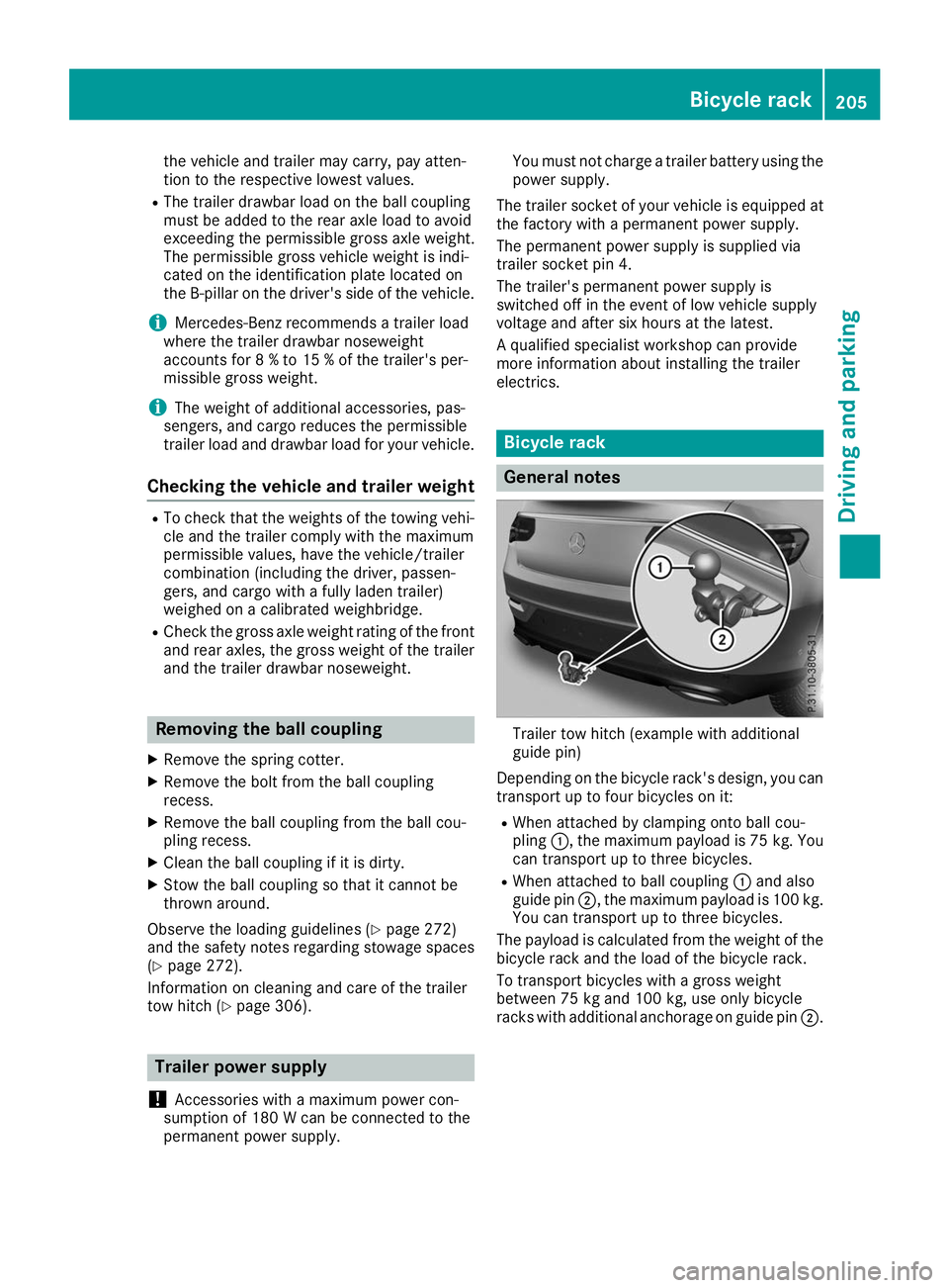
Trailer tow hitch (example with additional
guide pin)
Depending on the bicycle rack's design, you can transport up to four bicycles on it:
R When attached by clamping onto ball cou-
pling 0043, the maximum payload is 75 kg. You
can transport up to three bicycles.
R When attached to ball coupling 0043and also
guide pin 0044, the maximum payload is 100 kg.
You can transport up to three bicycles.
The payload is calculated from the weight of the
bicycle rack and the load of the bicycle rack.
To transport bicycles with a gross weight
between 75 kg and 100 kg, use only bicycle
racks with additional anchorage on guide pin 0044. Bicycle rack
205Driving and parking Z
Page 209 of 370
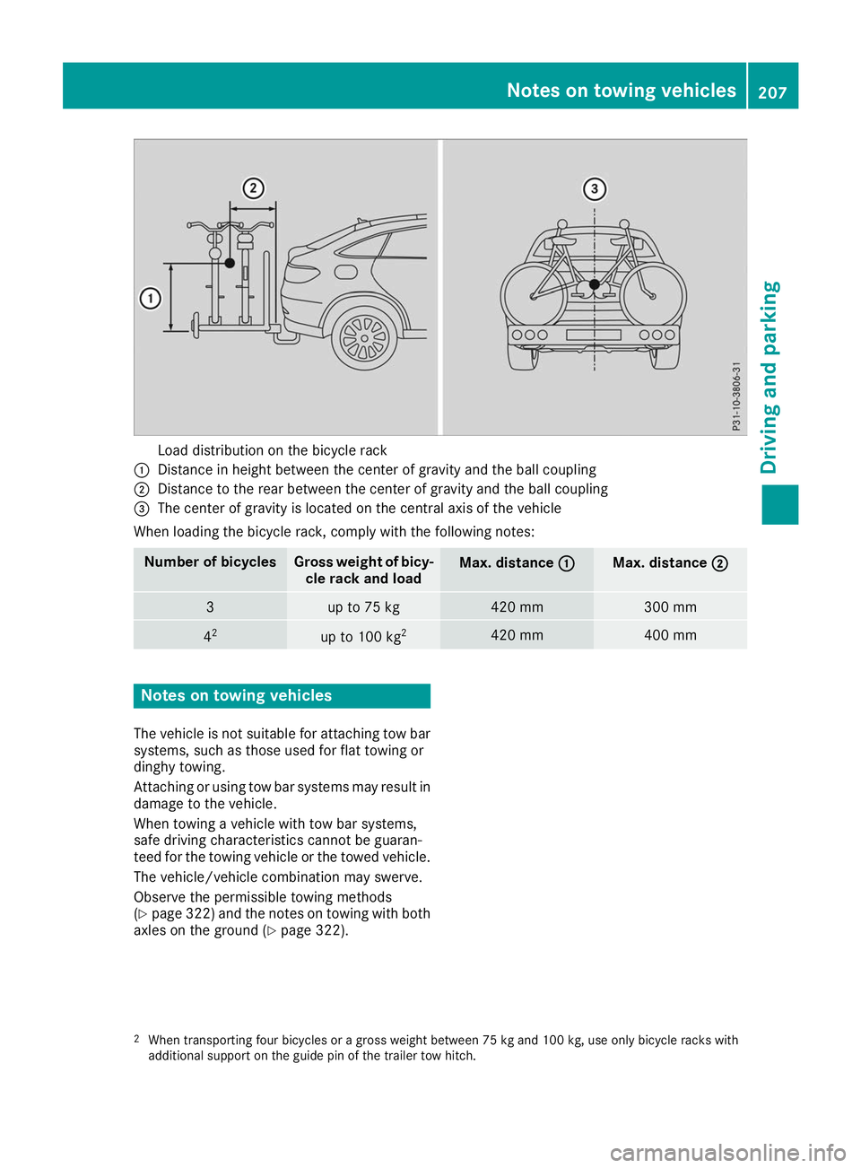
Load distribution on the bicycle rack
0043 Distance in height between the center of gravity and the ball coupling
0044 Distance to the rear between the center of gravity and the ball coupling
0087 The center of gravity is located on the central axis of the vehicle
When loading the bicycle rack, comply with the following notes: Number of bicycles Gross weight of bicy-
cle rack and load Max. distance
0043
0043 Max. distance
0044
0044 3 up to 75 kg 420 mm 300 mm
4
2 up to 100 kg
2 420 mm 400 mm
Notes on towing vehicles
The vehicle is not suitable for attaching tow bar
systems, such as those used for flat towing or
dinghy towing.
Attaching or using tow bar systems may result in
damage to the vehicle.
When towing a vehicle with tow bar systems,
safe driving characteristics cannot be guaran-
teed for the towing vehicle or the towed vehicle.
The vehicle/vehicle combination may swerve.
Observe the permissible towing methods
(Y page 322) and the notes on towing with both
axles on the ground (Y page 322).
2 When transporting four bicycles or a gross weight between 75 kg and 100 kg, use only bicycle racks with
additional support on the guide pin of the trailer tow hitch. Notes on towing vehicles
207Driving and parking Z
Page 315 of 370
X
Do not remove any foreign objects which have
penetrated the tire, e.g. screws or nails.
X Remove the tire sealant bottle, the accompa-
nying TIREFIT sticker and the tire inflation
compressor from the stowage well under-
neath the cargo compartment floor
(Y page 310).
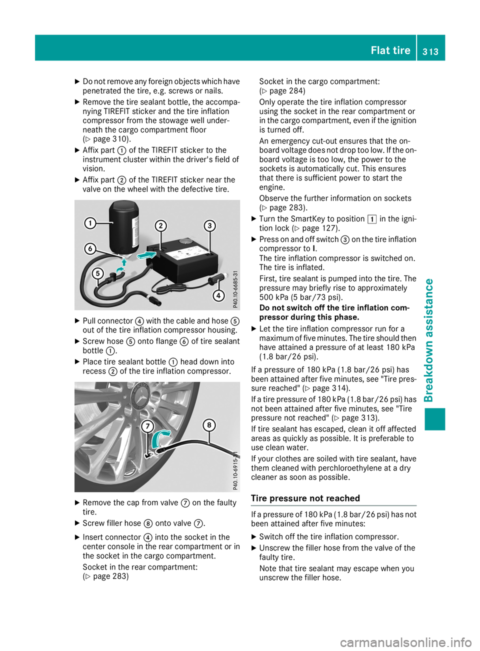
X Affix part 0043of the TIREFIT sticker to the
instrument cluster within the driver's field of
vision.
X Affix part 0044of the TIREFIT sticker near the
valve on the wheel with the defective tire. X
Pull connector 0085with the cable and hose 0083
out of the tire inflation compressor housing.
X Screw hose 0083onto flange 0084of tire sealant
bottle 0043.
X Place tire sealant bottle 0043head down into
recess 0044of the tire inflation compressor. X
Remove the cap from valve 006Bon the faulty
tire.
X Screw filler hose 006Conto valve 006B.
X Insert connector 0085into the socket in the
center console in the rear compartment or in
the socket in the cargo compartment.
Socket in the rear compartment:
(Y page 283) Socket in the cargo compartment:
(Y page 284)
Only operate the tire inflation compressor
using the socket in the rear compartment or
in the cargo compartment, even if the ignition
is turned off.
An emergency cut-out ensures that the on-
board voltage does not drop too low. If the on-
board voltage is too low, the power to the
sockets is automatically cut. This ensures
that there is sufficient power to start the
engine.
Observe the further information on sockets
(Y page 283).
X Turn the SmartKey to position 0047in the igni-
tion lock (Y page 127).
X Press on and off switch 0087on the tire inflation
compressor to I.
The tire inflation compressor is switched on.
The tire is inflated.
First, tire sealant is pumped into the tire. The
pressure may briefly rise to approximately
500 kPa (5 bar/73 psi).
Do not switch off the tire inflation com-
pressor during this phase.
X Let the tire inflation compressor run for a
maximum of five minutes. The tire should then have attained a pressure of at least 180 kPa
(1.8 bar/26 psi).
If a pressure of 180 kPa (1.8 ba r/26 psi) has
been at tained after five minutes, see "Tire pres-
sure reached" (Y page 314).
If a tire pressure of 180 kPa (1.8 bar/26 psi) has not been attained after five minutes, see "Tire
pressure not reached" (Y page 313).
If tire sealant has escaped, clean it off affected
areas as quickly as possible. It is preferable to
use clean water.
If your clothes are soiled with tire sealant, have them cleaned with perchloroethylene at a dry
cleaner as soon as possible.
Tire pressure not reached If a pressure of 180 kPa (1.8 bar/26 psi) has not
been attained after five minutes:
X Switch off the tire inflation compressor.
X Unscrew the filler hose from the valve of the
faulty tire.
Note that tire sealant may escape when you
unscrew the filler hose. Flat tire
313Breakdown assistance Z
Page 316 of 370
X
Very slowly drive forwards or reverse approx-
imately 30 ft (10 m).
X Pump up the tire again.
After a maximum of five minutes the tire pres-
sure must be at least 180 kPa (1.8 bar/
26 psi). G
WARNING
If the required tire pressure is not reached
after the specified time, the tire is too badly
damaged. The tire sealant cannot repair the
tire in this instance. Damaged tires and a tire pressure that is too low can significantly
impair the vehicle's braking and driving char-
acteristics. There is a risk of accident.
Do not continue driving. Contact a qualified
specialist workshop.
Tire pressure reached G
WARNING
A tire temporarily sealed with tire sealant
impairs the vehicle's driving characteristics
and is not suitable for driving at higher
speeds. There is a risk of an accident.
Adapt your driving style accordingly and drive carefully. Do not exceed the maximum per-
missible speed for a tire sealed with tire seal- ant.
The maximum permissible speed for a tire
sealed with tire sealant is 50 mph (80 km/h).
The upper part of the TIREFIT sticker must be
affixed to the instrument cluster in the driver's
field of vision.
! Residue from the tire sealant may come out
of the filler hose after use. This could cause
stains.
Therefore, place the filler hose in the plastic
bag which contained the TIREFIT kit. H
Environmental note
Have the used tire sealant bottle disposed of
professionally, e.g. at a qualified specialist
workshop. If a tire pressure of 180 kPa (1.8 bar/26 psi) has
been attained after five minutes:
X Switch off the tire inflation compressor.
X Unscrew the filler hose from the valve of the
faulty tire.
X Stow the tire sealant bottle and the tire infla-
tion compressor.
X Pull away immediately.
X Stop after driving for approximately ten
minutes and check the tire pressure with the tire inflation compressor.
The tire pressure must now be at least
130 kPa (1.3 bar/19 psi). G
WARNING
If the required tire pressure is not reached
after driving for a short period, the tire is too
badly damaged. The tire sealant cannot repair the tire in this instance. Damaged tires and a
tire pressure that is too low can significantly
impair the vehicle's braking and driving char-
acteristics. There is a risk of accident.
Do not continue driving. Contact a qualified
specialist workshop.
i In cases such as the one mentioned above,
contact an authorized Mercedes-Benz Cen-
ter. Or call 1-800-FOR-MERCedes (in the
USA) or 1-800-387-0100 (in Canada).
X Correct the tire pressure if it is still at least
130 kPa (1.3 bar/19 psi). See the Tire and
Loading Information placard on the driver's
side B-pillar or the tire pressure table in the
fuel filler flap for values.
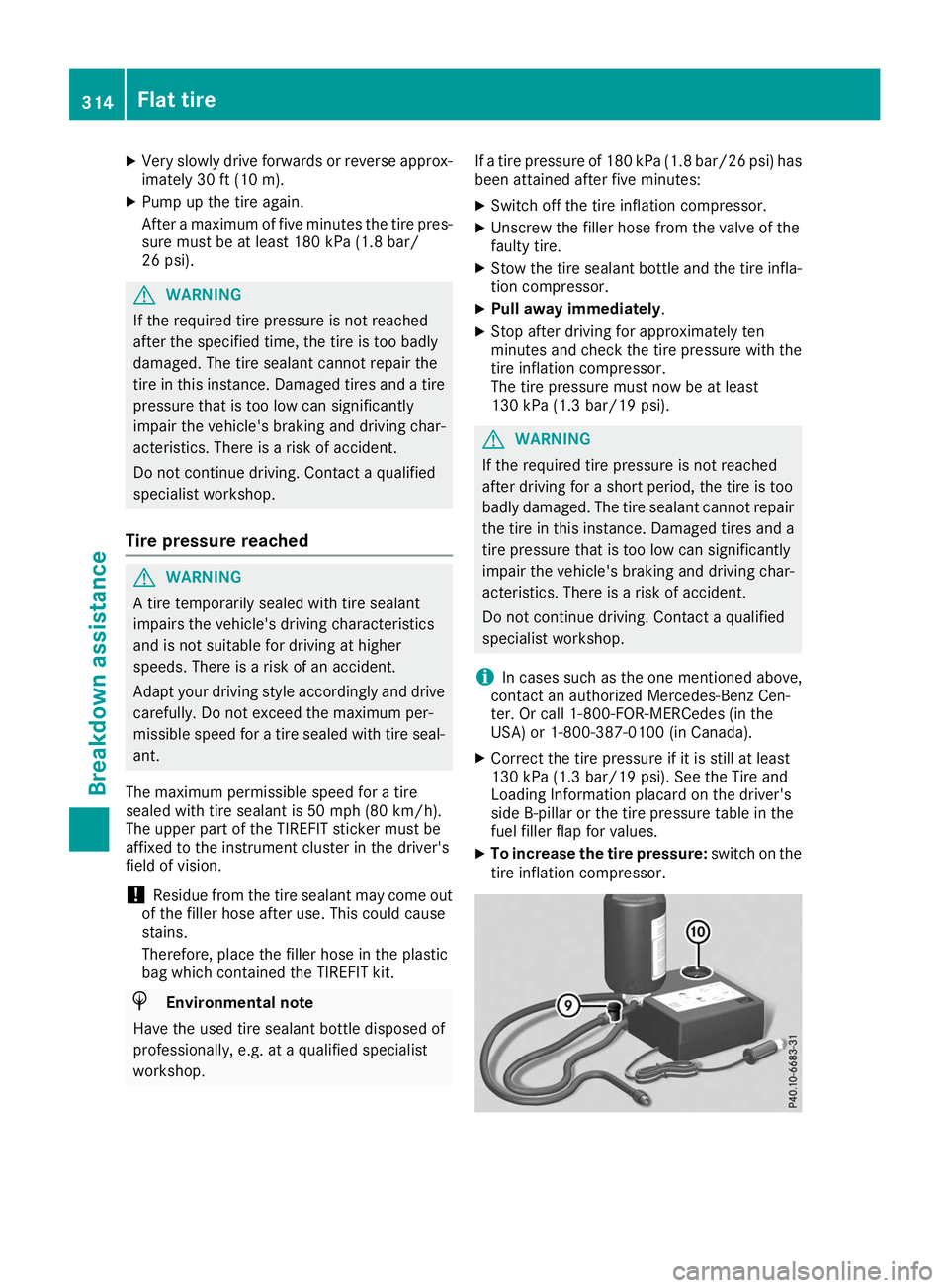
X To increase the tire pressure: switch on the
tire inflation compressor. 314
Flat tireBreakdown assistance
Page 323 of 370
Towing and tow-starting
Important safety notes
G
WARNING
Functions relevant to safety are restricted or
no longer available if:
R the engine is not running.
R the brake system or the power steering is
malfunctioning.
R there is a malfunction in the voltage supply
or the vehicle's electrical system.
If your vehicle is being towed, much more
force may be necessary to steer or brake.
There is a risk of an accident.
In such cases, use a tow bar. Before towing,
make sure that the steering moves freely. G
WARNING
When towing or tow-starting another vehicle
and its weight is greater than the permissible gross weight of your vehicle, the:
R the towing eye could detach itself
R the vehicle/trailer combination could roll-
over.
There is a risk of an accident.
When towing or tow-starting another vehicle,
its weight should not be greater than the per- missible gross weight of your vehicle.
Details on the permissible gross vehicle weight
of your vehicle can be found on the vehicle iden-
tification plate (Y page 358).
! When Active Brake Assist, Active Distance
Assist DISTRONIC or the HOLD function is
activated, the vehicle brakes automatically in
certain situations.
To avoid damage to the vehicle, deactivate
these systems in the following or similar sit-
uations:
R when towing the vehicle
R in the car wash
! Make sure that the electric parking brake is
released. If the electric parking brake is faulty,
visit a qualified specialist workshop. !
Only secure the tow rope or tow bar at the
towing eyes, or the trailer tow hitch, if availa-
ble. You could otherwise damage the vehicle.
! Observe the following points when towing
with a tow rope:
R Secure the tow rope on the same side on
both vehicles.
R Make sure that the tow rope is not longer
than legally permitted. Mark the tow rope in
the middle, e.g. with a white cloth
(11.8 x 11.8 in). This will make other road
users aware that a vehicle is being towed.
R Only secure the tow cable to the towing
eyes or, if available, to the trailer tow hitch.
R Observe the brake lamps of the towing
vehicle while driving. Always maintain a dis-
tance a distance so that the tow rope does not sag.
R Do not use steel cables or chains to tow
your vehicle. You could otherwise damage
the vehicle.
! Do not use the trailer tow hitch for recovery
or towing. Do not use the towing eye for
recovery. this could damage the vehicle. If in
doubt, have the vehicle recovered using a
crane.
! When towing, pull away slowly and
smoothly. Pull the towed vehicle as straight as possible and not at an acute angle. Excessive
tractive power could damage the vehicles.
When towing, it is preferable to use a rigid tow-
ing bar as opposed to a tow rope. A rigid towing bar helps to keep the tractive power low.
! When towing away vehicles with KEYLESS-
GO, use the key instead of the Start/Stop
button. The automatic transmission may oth-
erwise shift to position 005Dwhen you open the
driver's or front-passenger door, which could damage the transmission.
! Do not tow with sling-type equipment. This
could damage the vehicle.
! Vehicles with differential locks: make sure
the differential locks are in automatic mode.
When towing, the differential locks must not
be switched on. The transmission may other- wise be damaged.
! You may tow the vehicle for a maximum dis-
tance of 30 miles (50 kilometers). A towing Towing and tow-starting
321Breakdown assistance Z
Page 324 of 370
speed of 30 mph (50 km/h) must not be
exceeded.
For towing distances over 30 miles
(50 kilometers), the entire vehicle must be
raised and transported.
It is better to have the vehicle transported than
to have it towed away.
If the vehicle has suffered transmission damage, have it transported on a transporter or trailer.
The automatic transmission must be in position
005C when the vehicle is being towed.
The battery must be connected and charged.
Otherwise, you:
R cannot turn the SmartKey to position 0048in
the ignition lock
R cannot release the electric parking brake
R cannot shift the automatic transmission to
position 005C
Disarm the automatic locking feature before the vehicle is towed (Y page 219). You could other-
wise be locked out when pushing or towing the
vehicle. Permitted towing methods
Mercedes-Benz recommends transporting your
vehicle in the case of a breakdown, rather than
towing it away.
When towing away, use a towing rope or a tow-
ing bar with both axles on the ground. Do not use any tow bar systems. Installing/removing the towing eye
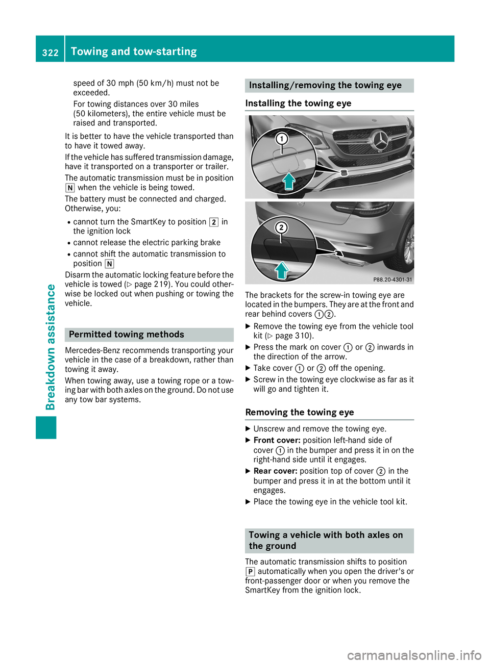
Installing the towing eye The brackets for the screw-in towing eye are
located in the bumpers. They are at the front and
rear behind covers 00430044.
X Remove the towing eye from the vehicle tool
kit (Y page 310).
X Press the mark on cover 0043or0044 inwards in
the direction of the arrow.
X Take cover 0043or0044 off the opening.
X Screw in the towing eye clockwise as far as it
will go and tighten it.
Removing the towing eye X
Unscrew and remove the towing eye.
X Front cover: position left-hand side of
cover 0043in the bumper and press it in on the
right-hand side until it engages.
X Rear cover: position top of cover 0044in the
bumper and press it in at the bottom until it
engages.
X Place the towing eye in the vehicle tool kit. Towing a vehicle with both axles on
the ground
The automatic transmission shifts to position
005D automatically when you open the driver's or
front-passenger door or when you remove the
SmartKey from the ignition lock. 322
Towing and tow-startingBreakdown assistance